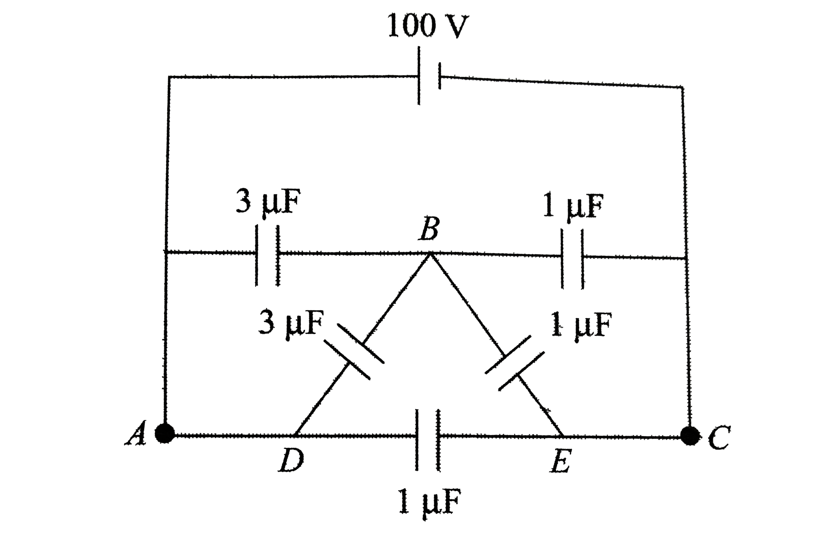
In the system is in steady state. Then
a. VA−VB=_______
b. VB−VC=______
c. VD−Ve=______
d. The energy stored in the circuit is "________"
 .
.
Video Solution
Text Solution
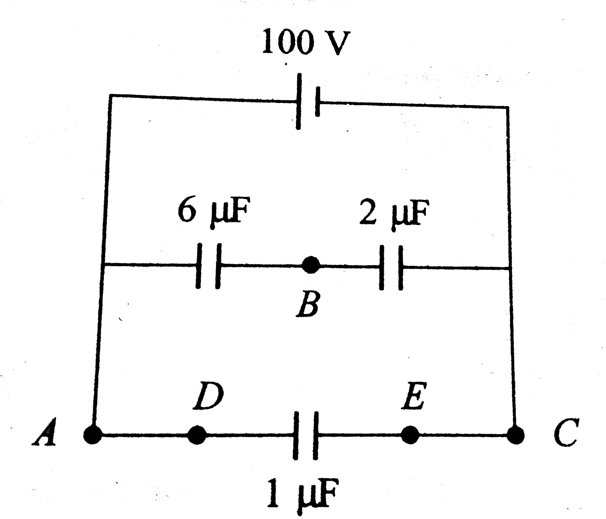
Both 3μF capacitors will be in parallel, and similarly upper two 1μF capacitors will be in parallel. The circuit may be redrawn as follows:
 .
.
a. VA−VB=100×26+2=25V
b. VA−VC=100×66+2=75V
c. VD−VE=100V
d. Ceq=6×26+2+1=52μF
U=12CeqV2=12(52×10−6)×(100)2
=125×10−4J.
|
Topper's Solved these Questions
- CAPACITOR AND CAPACITANCEBOOK - CENGAGE PHYSICSCHAPTER - CAPACITOR AND CAPACITANCEEXERCISE - Subjective
24 Videos
- CAPACITOR AND CAPACITANCEBOOK - CENGAGE PHYSICSCHAPTER - CAPACITOR AND CAPACITANCEEXERCISE - Single Correct
49 Videos
- CAPACITOR AND CAPACITANCEBOOK - CENGAGE PHYSICSCHAPTER - CAPACITOR AND CAPACITANCEEXERCISE - Exercise 4.1
13 Videos
- ATOMSBOOK - CENGAGE PHYSICSCHAPTER - ATOMSEXERCISE - QUESTION BANK
40 Videos
- CENGAGE PHYSICS DPPBOOK - CENGAGE PHYSICSCHAPTER - CENGAGE PHYSICS DPPEXERCISE - subjective type
51 Videos
Similar Questions
Knowledge Check
Find VA−VB in steady state
 A8VB16VC24VDnone of the above
In adjacent circuit VA−VB will be -
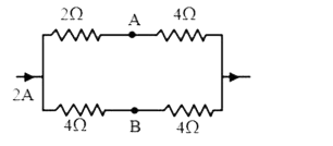 A4VB2VC3VD1V
In the circuit shown in the figure, the ratio of VB as VC is
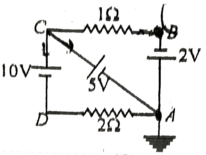 A−2/5B−5/2C1D1/3
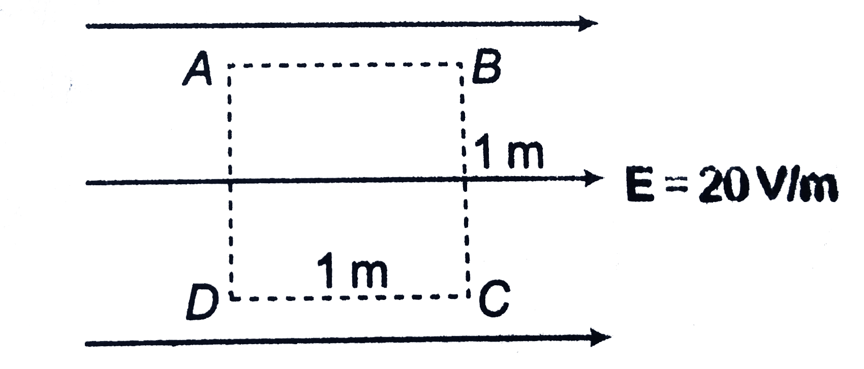
In the uniform electric field shown in figure, find :
a. VA−VD
b. VA−VC
c. VB−VD
d. VC−VD
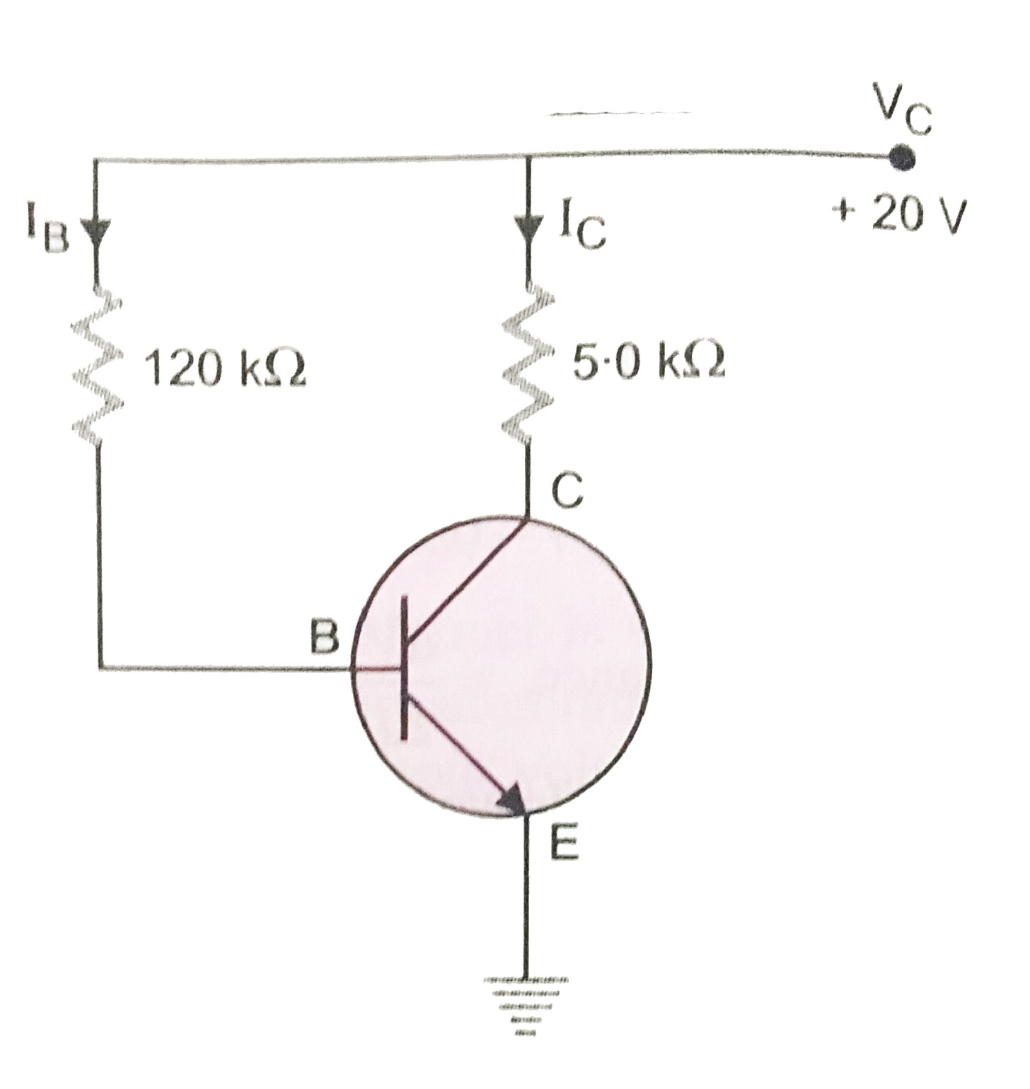
View SolutionIn the circuit Fig. the value of beta is 200. Find IB,VCE,VBE and VBC, when IC=2.5mA. The transistor is in active, cut off or saturation state.
View SolutionIn uniform electric field E=10N/C, find
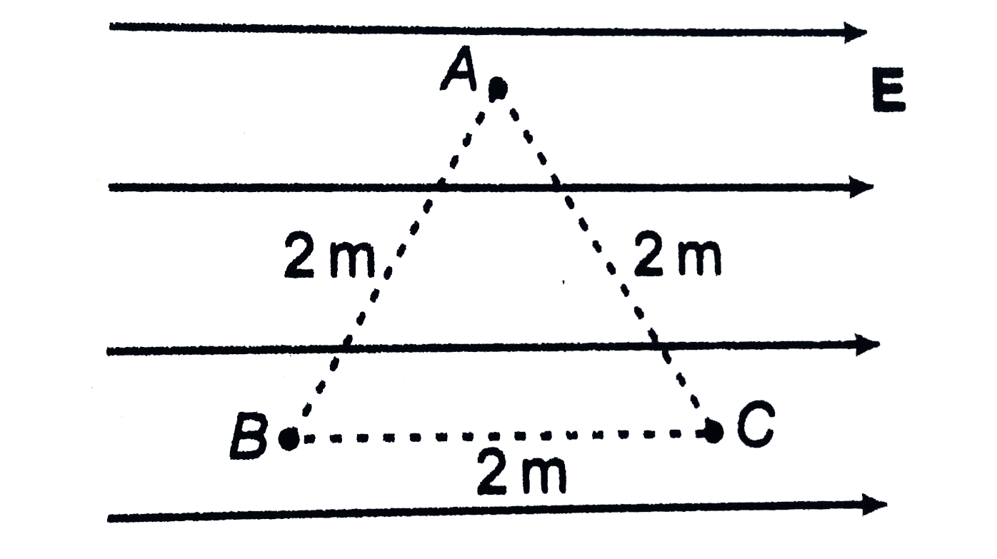
a. VA−VB , b. VB−VC
View SolutionVA⋅VB for given figure in steady state is
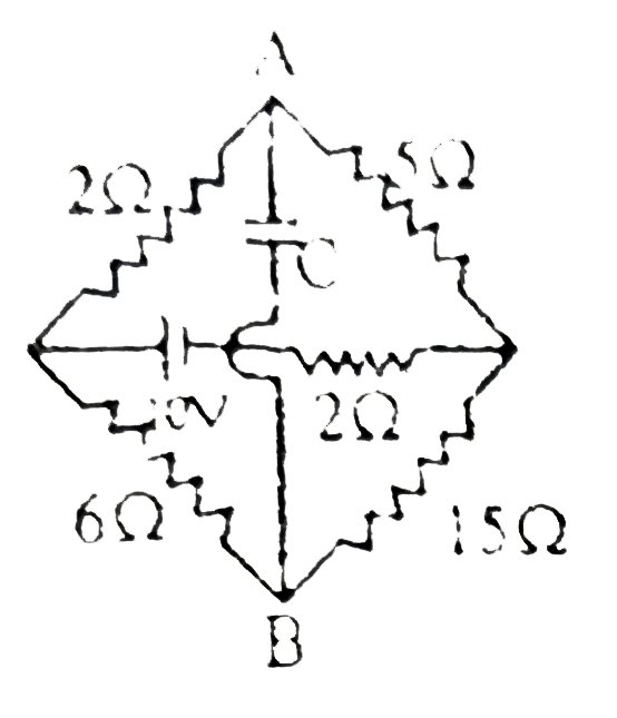
View SolutionIn the circuit shown in the figure, the input voltage Vi is 20V,VBE=0 and VCE=0. The values of IB,IC and β are given by:
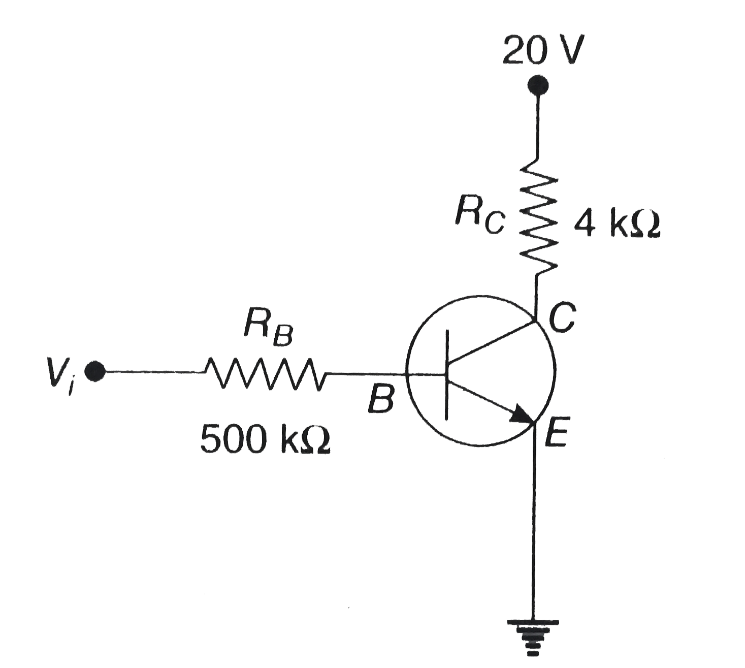
View Solution


