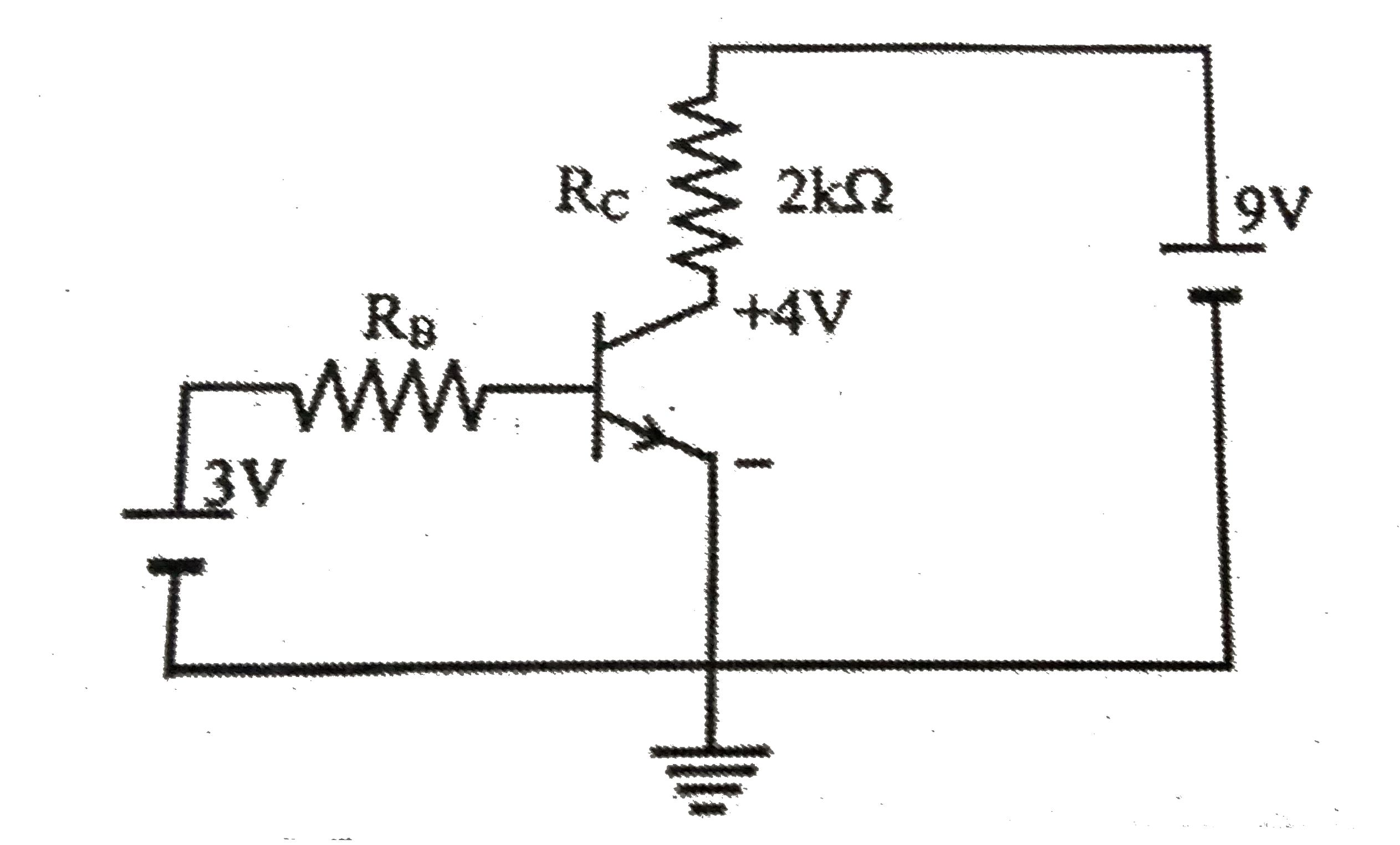
For the transistor circuit shown in figure , evaluate VE,RBandRE. Given IC=1mA,
VCE=3V,VBE=0.5V,VC=12Vandβ=1000
Video Solution
Text Solution
The correct Answer is:A, B
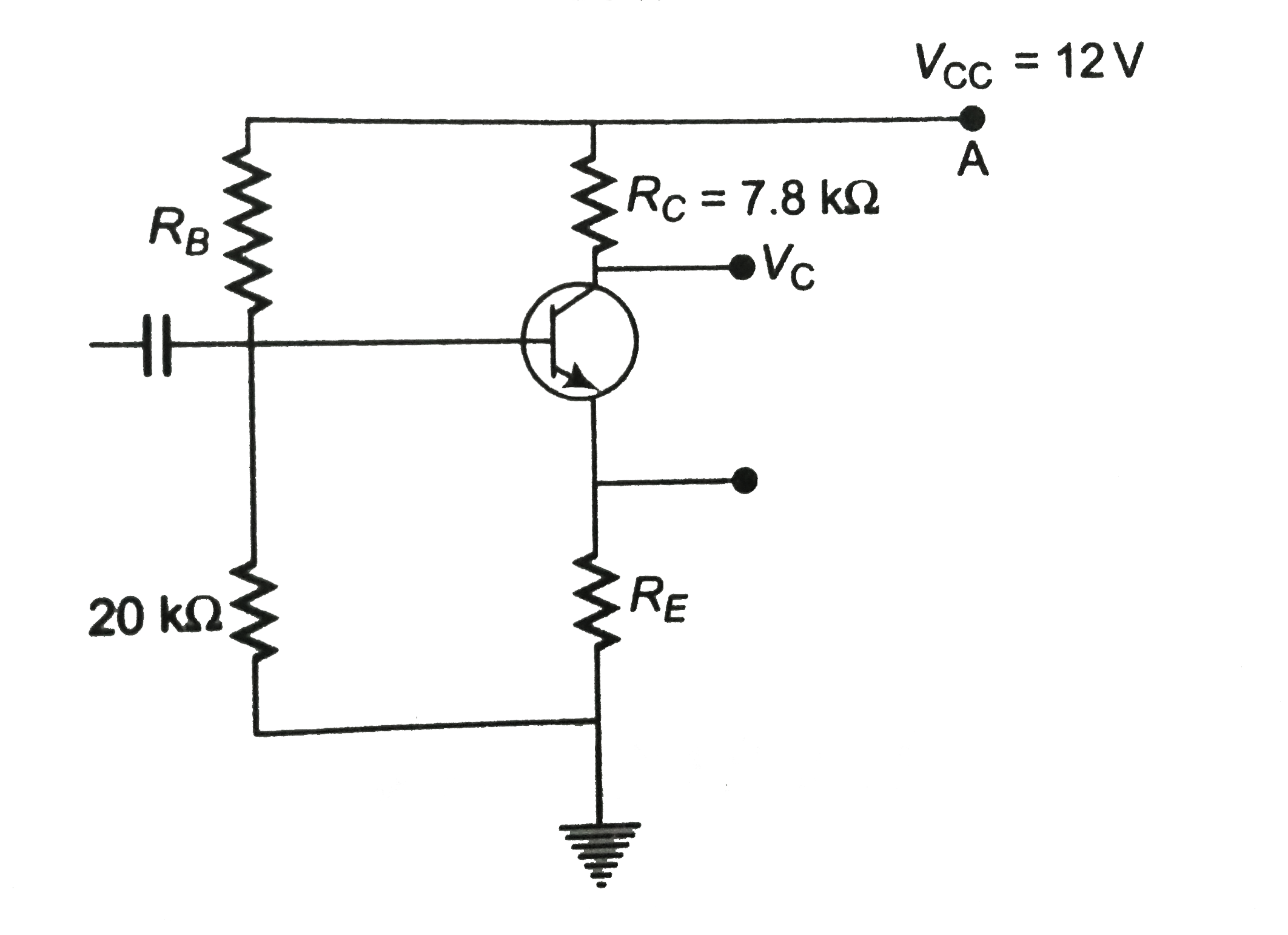
Consider the figure given here to solve this problem
IC=IE [As base current is very small]
RC=7.8KΩ
From the figure, IC(RC+RE)+VCE=12
(RE+RC)×1×10⁻³+3=12
RE+RC=9×103=9kΩ
RE=9−7.8=1.2kΩ
VE=IE×RE
=1×10−3×1.2×103=1.2V
Voltage , VB=VE+VBE=1.2+0.5=1.7V
Current, I=VB20×103=1.720×103
=0.085mA
Resistance , RB=12−1.71Cβ+0.085=10.30.01+0.085 [ Given , β=100]
=108kΩ
(##DCP_V05_C35_E01_026_S01.png" width="80%">
|
Topper's Solved these Questions
- SEMICONDUCTORSBook:DC PANDEYChapter:SEMICONDUCTORSExercise:More Than One Correct
Explore 6 Videos
- REFRACTION OF LIGHTBook:DC PANDEYChapter:REFRACTION OF LIGHTExercise:Level 2 Subjective
Explore 21 Videos
- SOLVED PAPER 2017Book:DC PANDEYChapter:SOLVED PAPER 2017Exercise:Solved papers 2017(JIPMER)
Explore 32 Videos
Similar Questions
Knowledge Check
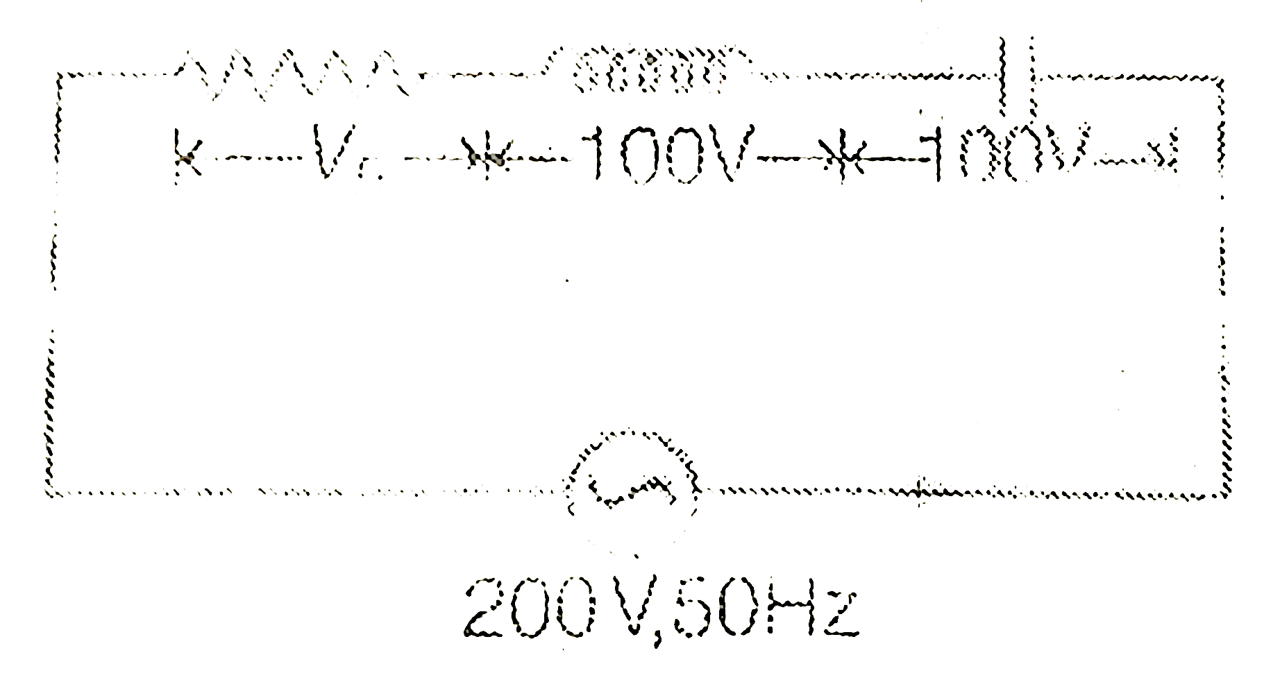
In the circuit shown in figure value of VR is
 A400VB200VC300VDzero
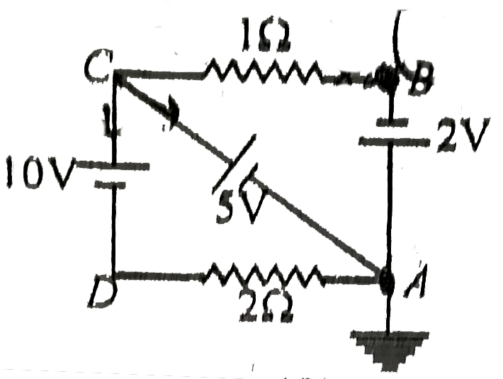
In the circuit shown in the figure, the ratio of VB as VC is
 A−2/5B−5/2C1D1/3
Find VP−VQ in the circuit shown in figure.
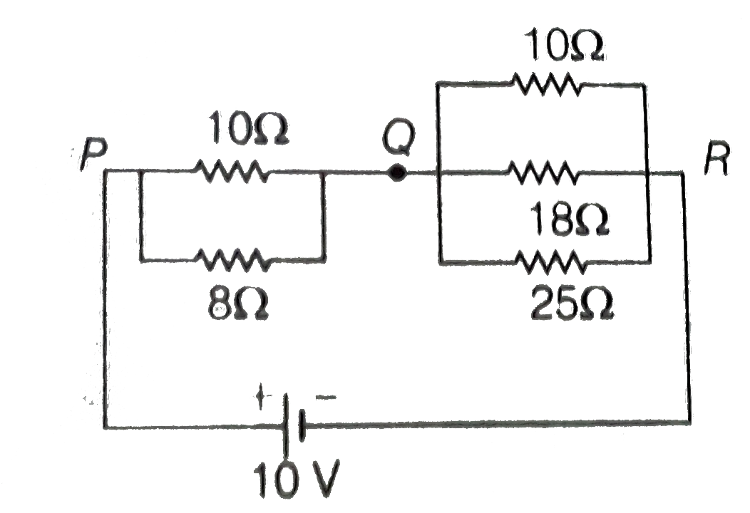 A6.68 VB8 VC4.65 VD7 V
In the circuit shown in the figure, the input voltage Vi is 20V, VBE=0 and VCE=0. The values of IB, IC and β are given by
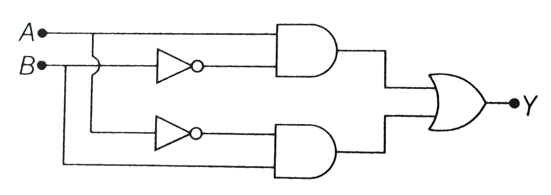
View SolutionIn the circuit shown in the figure, the input voltage Vi is 20V,VBE=0 and VCE=0. The values of IB,IC and β are given by:
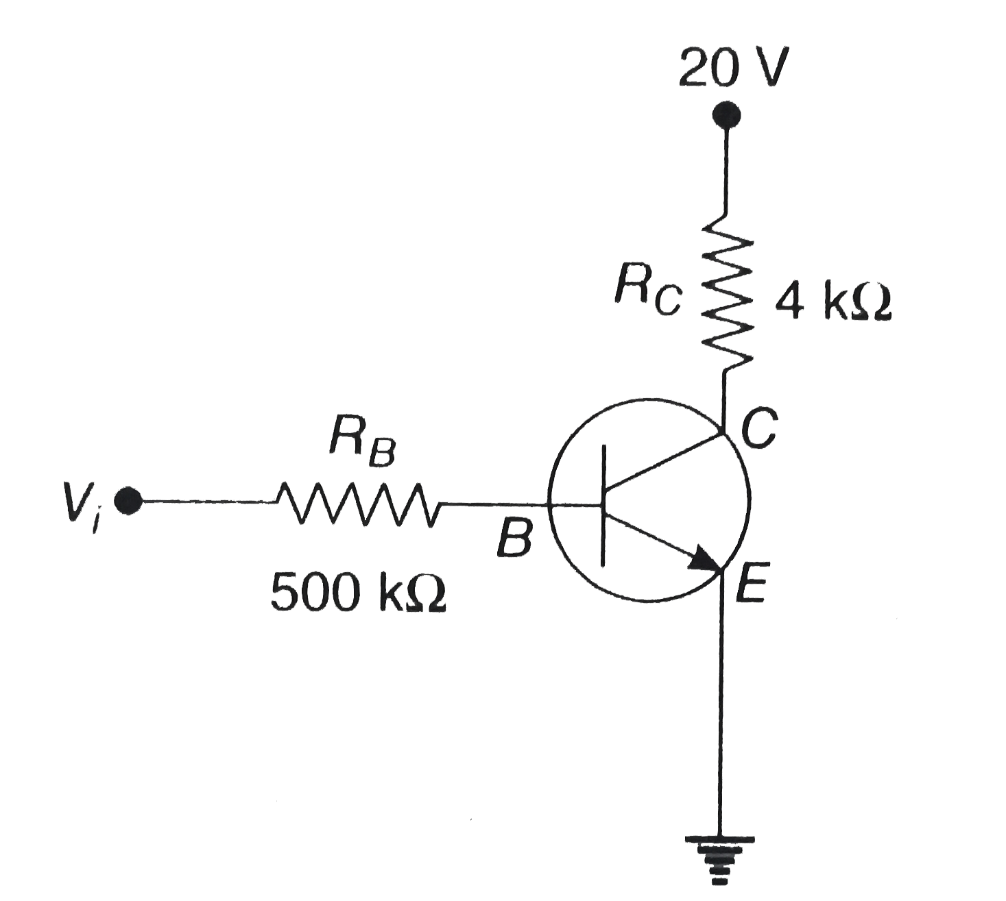
View SolutionIn the circuit shown in the figure, the input voltage Vi is 20V,VBE=0 and VCE=0. The values of IB,IC and β are given by:

View SolutionIn the circuit shows in the figure, the input voltage
Vi is 20 V, VBE=0 and VCE=0. The values of lB,lC and β are given by
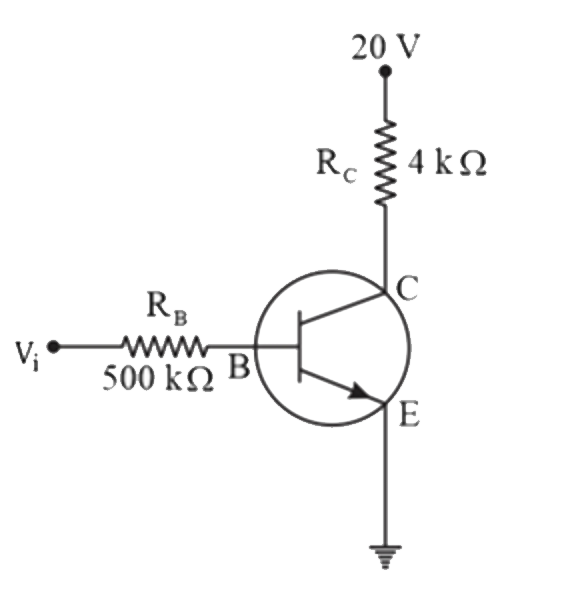
View SolutionPassage I
An n-p-n transistor is used as a voltage amplifier in a commoin emitter circuit given
VC=8VIC=4mA
VCE=4V,
(VBE=0.6V,VBB=8V
βDc=200
The value of base resistance is
View Solution

