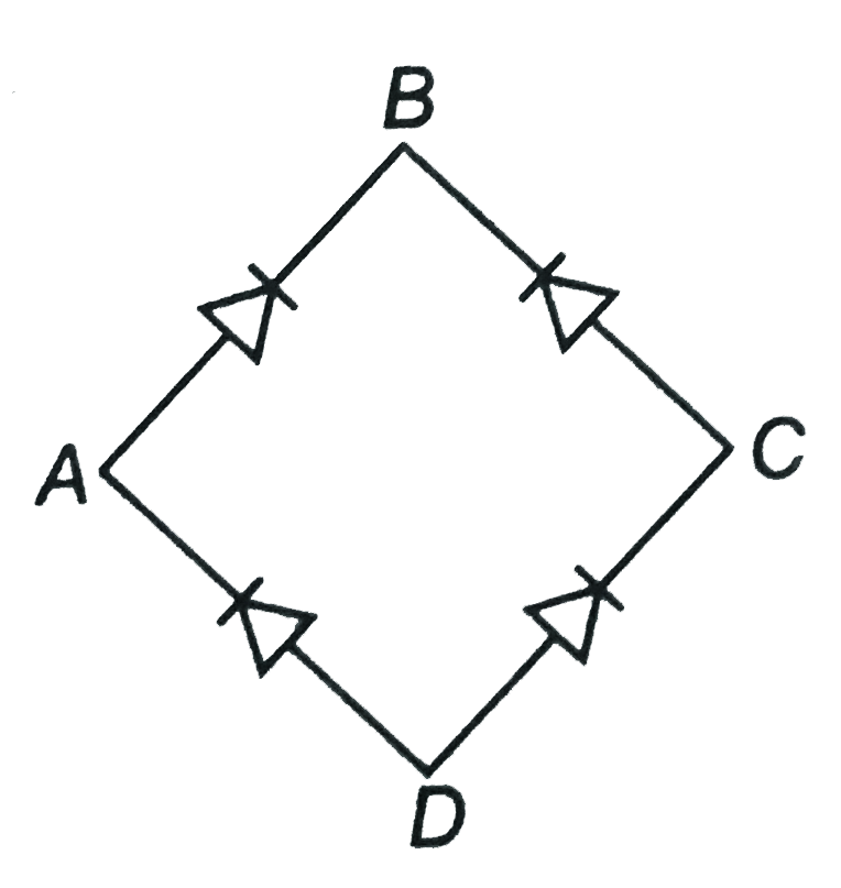
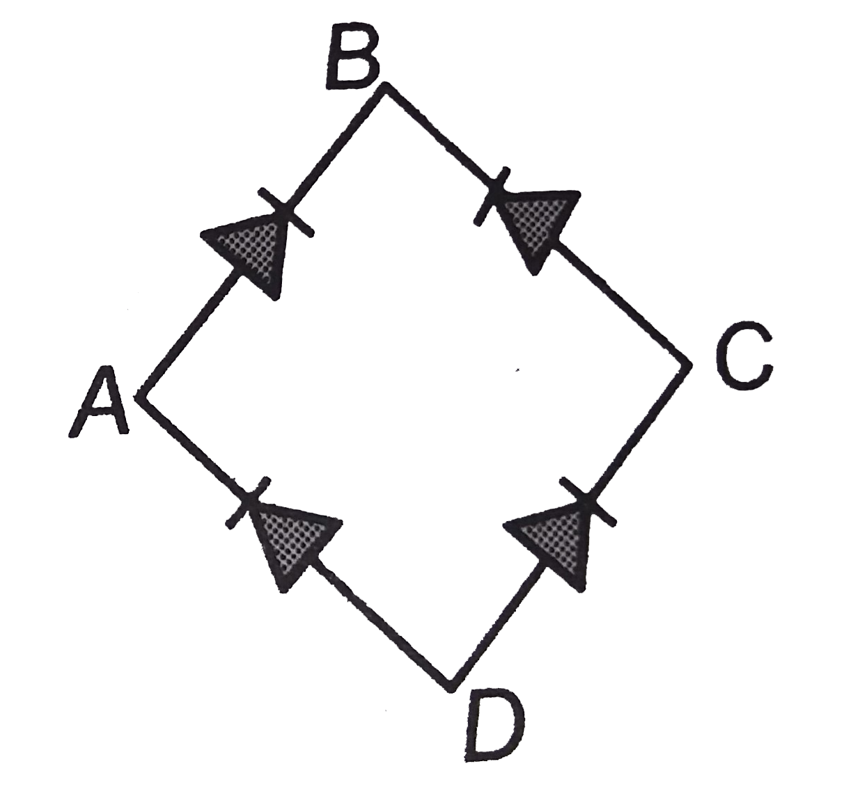
In the figure, the input is across the terminals
A and C and the output is across B and D. Then the output is
(a ) zero
( b) same as the input
( c) full - wave rectified
(d) half - wave rectified .
Video Solution
Text Solution
The correct Answer is:A
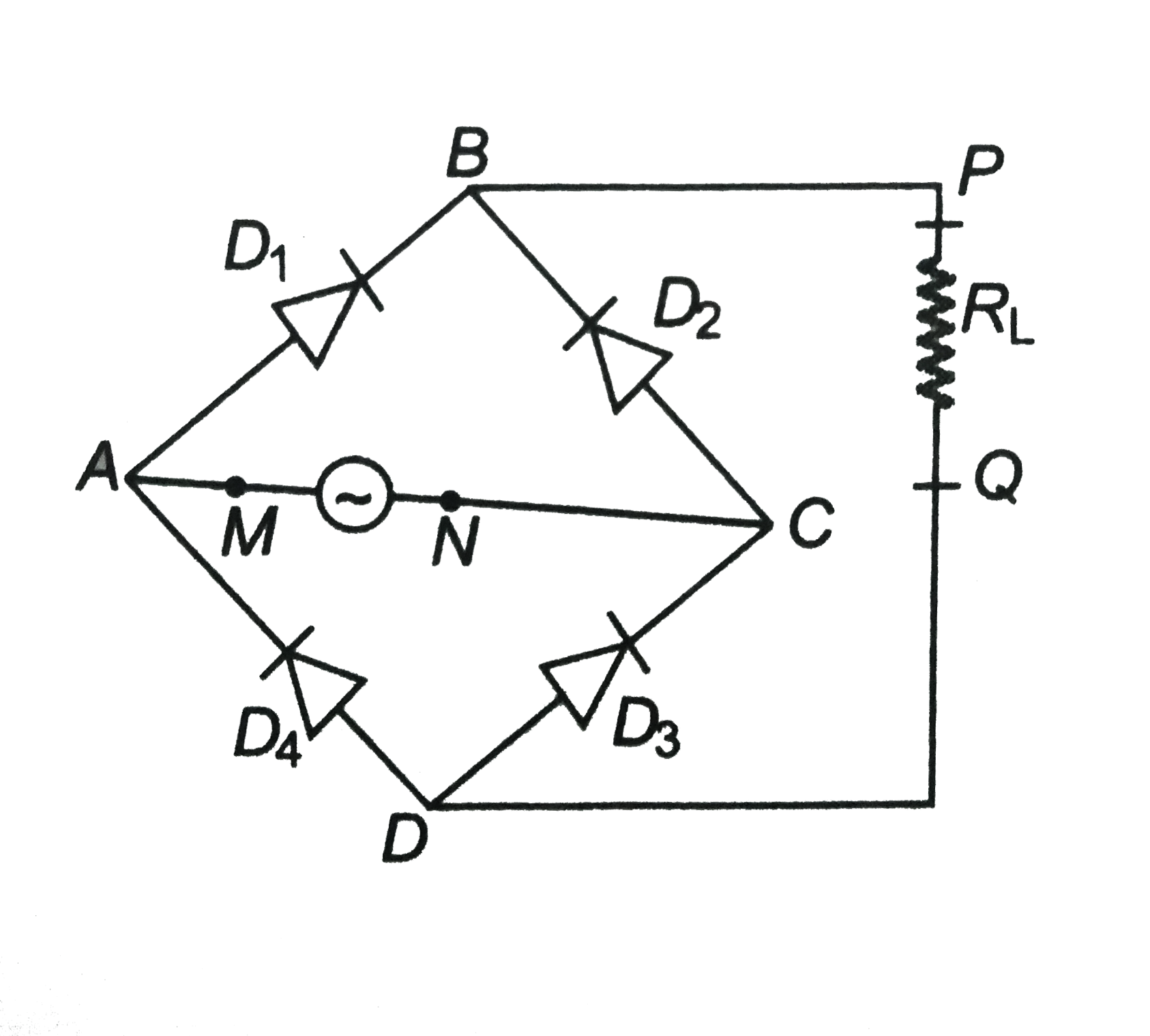
( c ) During the half cycle when are forward
biased. Hence , the path of current is MABPQDCNM.
In the second half cycle, when are forward
biased while and are reverse biased. Hence , the path of
current is NCBPQDAMN .
Therefore, in both half cycles current flows from P to Q from load
resistance . Or , it is a full - wave rectifier .
 .
.
|
Updated on:21/07/2023
Topper's Solved these Questions
- BOOK - DC PANDEYCHAPTER - SEMICONDUCTORSEXERCISE - Solved Example14videos
SEMICONDUCTORS
- BOOK - DC PANDEYCHAPTER - SEMICONDUCTORSEXERCISE - Exercise35.11videos
SEMICONDUCTORS
- BOOK - DC PANDEYCHAPTER - REFRACTION OF LIGHTEXERCISE - Level 2 Subjective21videos
REFRACTION OF LIGHT
- BOOK - DC PANDEYCHAPTER - SOLVED PAPER 2017EXERCISE - Solved papers 2017(JIPMER)32videos
SOLVED PAPER 2017
Similar Questions
Knowledge Check
- Question 1 - Select One
In Fig. the input is across the terminals A and C and the output is across B and D. Then the output is
 Ahalf wave rectifiedBfull wave rectifiedCzeroDsame as the input
 - Question 2 - Select One
In the diagram, the input is across the terminals A and C and the output is across the terminals B and D, then the outputs is
 AzeroBsame as inputCFull wave rectifierDHalf wave rectifier
 - Question 3 - Select One
The output form of full-wave rectifier is
AAn AC voltageBA DC voltageCZeroDA pulsating unidirectional voltage
Give any two differences between a half-wave rectifier and a full-wave rectifier.
View SolutionGive any two difference between a half wave rectifier and a full wave rectifier.
View SolutionIf the input frequency of half-wave rectifier is nHzac, then its output is
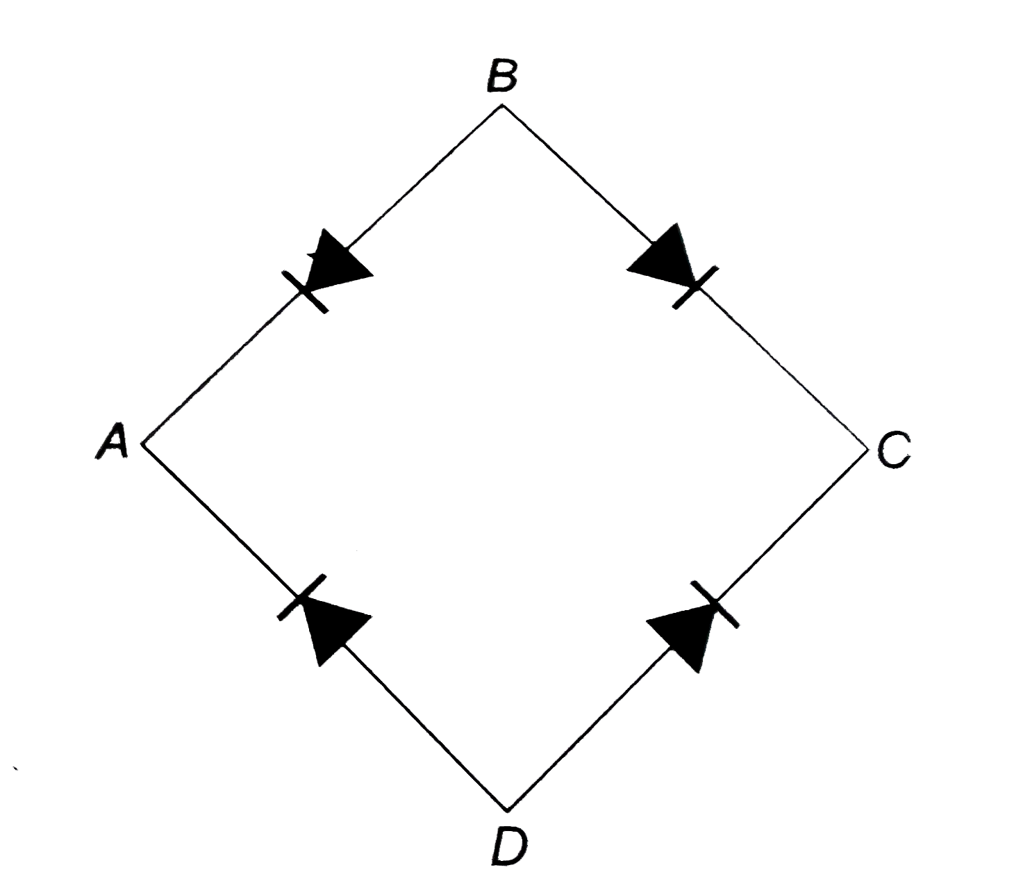
View SolutionA bridge rectifier is shown in figure. Alternating input is given across A and C. If output is taken across BD, then it is
 View Solution
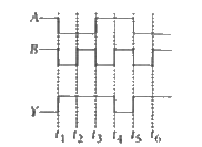
The figure shows the voltage waveforms across two inputs A and B and the output Y of a logic circuit. The logic circuit gate is
 View Solution


