A constant voltage is applied to a series R−L circuit by closing the switch. The voltage across inductor (L=2H) is 20V at t=0 and drops of 5V and 20ms. The value of R in Ω is
100ln2Ω
100(1−ln2)Ω
100ln4Ω
100(1−ln4)
The correct Answer is:C
Value remains 14th in 20ms times. Hence, two half-lives equal to 20ms. So, one half life is 10ms.
t1/2=(ln2)τC=(ln2)LR
∴R=(ln2)Lt1/2
=(ln2)(2)10×10−3=(100ln4)Ω
Topper's Solved these Questions
- ELECTROMAGNETIC INDUCTIONBOOK - DC PANDEYCHAPTER - ELECTROMAGNETIC INDUCTIONEXERCISE - Objective Questions
3 Videos
- ELECTROMAGNETIC INDUCTIONBOOK - DC PANDEYCHAPTER - ELECTROMAGNETIC INDUCTIONEXERCISE - Level 1 Subjective
21 Videos
- ELECTROMAGNETIC INDUCTIONBOOK - DC PANDEYCHAPTER - ELECTROMAGNETIC INDUCTIONEXERCISE - Level 1 Assertion And Reason
10 Videos
- CURRENT ELECTRICITYBOOK - DC PANDEYCHAPTER - CURRENT ELECTRICITYEXERCISE - Medical entrances gallery
97 Videos
- ELECTROMAGNETIC WAVESBOOK - DC PANDEYCHAPTER - ELECTROMAGNETIC WAVESEXERCISE - Sec C
22 Videos
Similar Questions
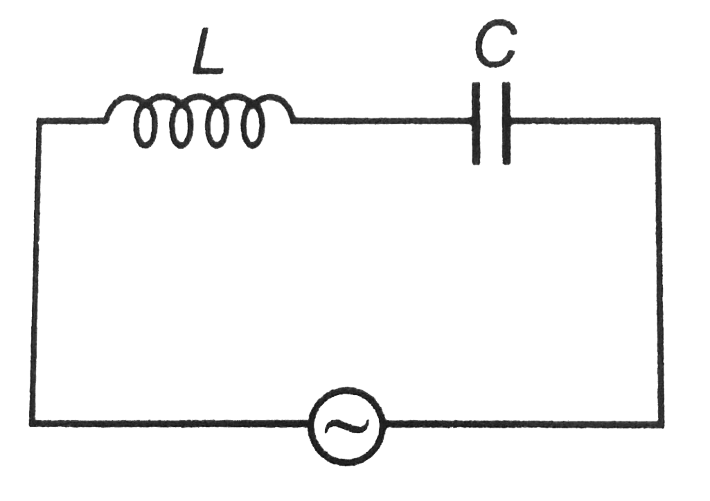
In a series L−C circuit, the applied voltage is V0. if omega is very low, then the voltage drop across the inductor VL and capacitor VC are
 .
.
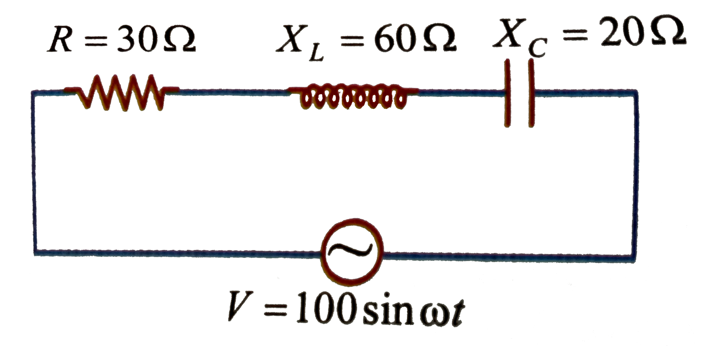
View SolutionAn alternating voltage V=100sinωt is applied across an LCR circuit as shown. At the instant when voltage drop across source is 50√3 volts then at that instant
R=30Ω XL=60Ω XC=20Ω

View Solution
Knowledge Check
In series L−C−R circuit, voltage drop across resistance is 8V, across inductor is 6V and across capacitor is 12V. Then,
Avoltage of the source will be leading in the circuitBvoltage drop across each element will be less than the applied voltageCpower factor of the circuit will be 34Dnone of the aboveIn series LCR circuit voltage drop across resistance is 8V, across inductor is 6V and across capacitor is 12V. Then
Avoltage of the source will be leading current in the circuitBvoltage drop across each element will be less than the applied voltage.Cpower factor of circuit will be 4/3Dnone of these.An AC voltage is applied acrss a series combination of L and R. If the voltage drop across the resistor and inductor are 20V and 15V respectiely, then applied peak voltage is
A25VB35VC25√2VD5√7V
A sinusoidal voltage Vsin(at) is applied across a series combination of resistance R and inductor L. The amplitude of the current in the circuit is
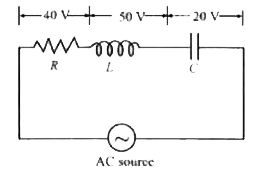
View SolutionIn series LCR circuit, the voltages across R, L and C shown in figure. The voltage of applied source is

View SolutionIn a series resonant circuit, the ac, voltage across resistance R, inductance L and capacitance Care 5V, 10V and 10V, respectively. The ac. voltage applied to the circuit will be
View SolutionIn a series resonant circuit, the AC voltage across resistance R, inductance L, and capacitance C are 5V,10V and 10V respectively. The AC voltage applied to the circuit will be
View SolutionIn an L-C-R circuit the AC voltage across R, L and C comes out as 10 V , 10 V and 20 V respectively . The voltage across the enter combination will be
View Solution
