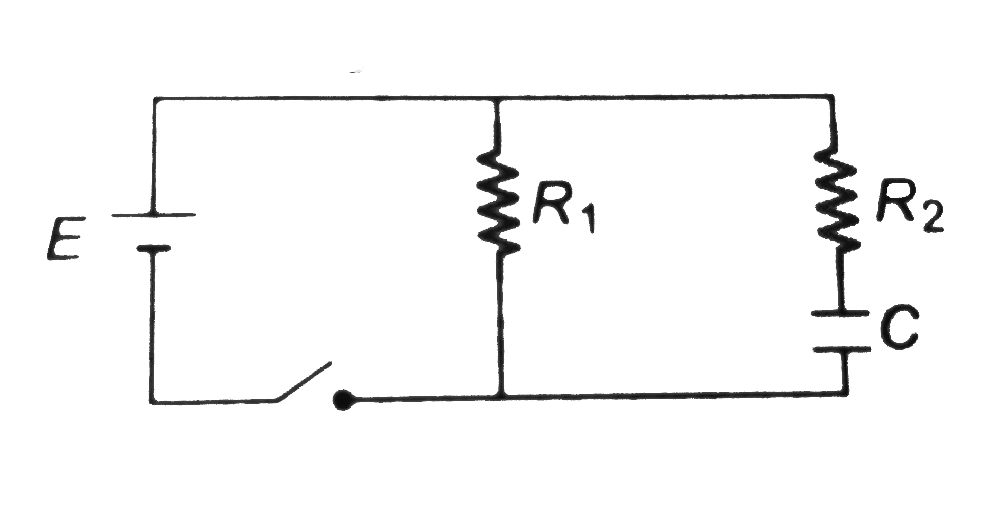
For the circuit shown in figure, find
(a) the initial current through each resistor
(b) steady state current through each resistor
(c) final energy stored in the capacitor
(d) time constant of the circuit when switch is opened.
Video Solution
Text Solution
The correct Answer is:A, B, C
a. At t=0 equivalent resistance of capacitor is zero. R1 and R2 are in parallel across the battery PD across each is E.
∴iR1=ER1
iR2=ER2
b. In steady state, no current flow thruogh capacitor wire. PD acorss R1 is E.
∴iR1=ER1 and iR2=0
c. In steady state, potential difference across capacitor is E.
∴U=12CV2=12CE2
d. When switch is opened capacitor is discharged throgh resistors R1 and R2
τC=CRnet
=C(R1+R2)
|
Topper's Solved these Questions
- CAPACITORSBook:DC PANDEYChapter:CAPACITORSExercise:OBJECTIVE_TYPE
Explore 1 Video
- CAPACITORSBook:DC PANDEYChapter:CAPACITORSExercise:OBJECTIVE_TYPE
Explore 1 Video
- ATOMSBook:DC PANDEYChapter:ATOMSExercise:MEDICAL ENTRANCES GALLERY
Explore 42 Videos
- COMMUNICATION SYSTEMBook:DC PANDEYChapter:COMMUNICATION SYSTEMExercise:Subjective
Explore 11 Videos
Similar Questions
Knowledge Check
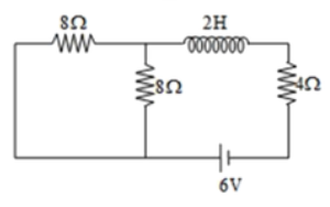
Consider a circuit as shown in the figure.
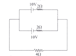
What is the current through 4 resistor ?A3AB1AC4AD2AFor the circuit shown in the figure, the current in the 4Ω resistor is
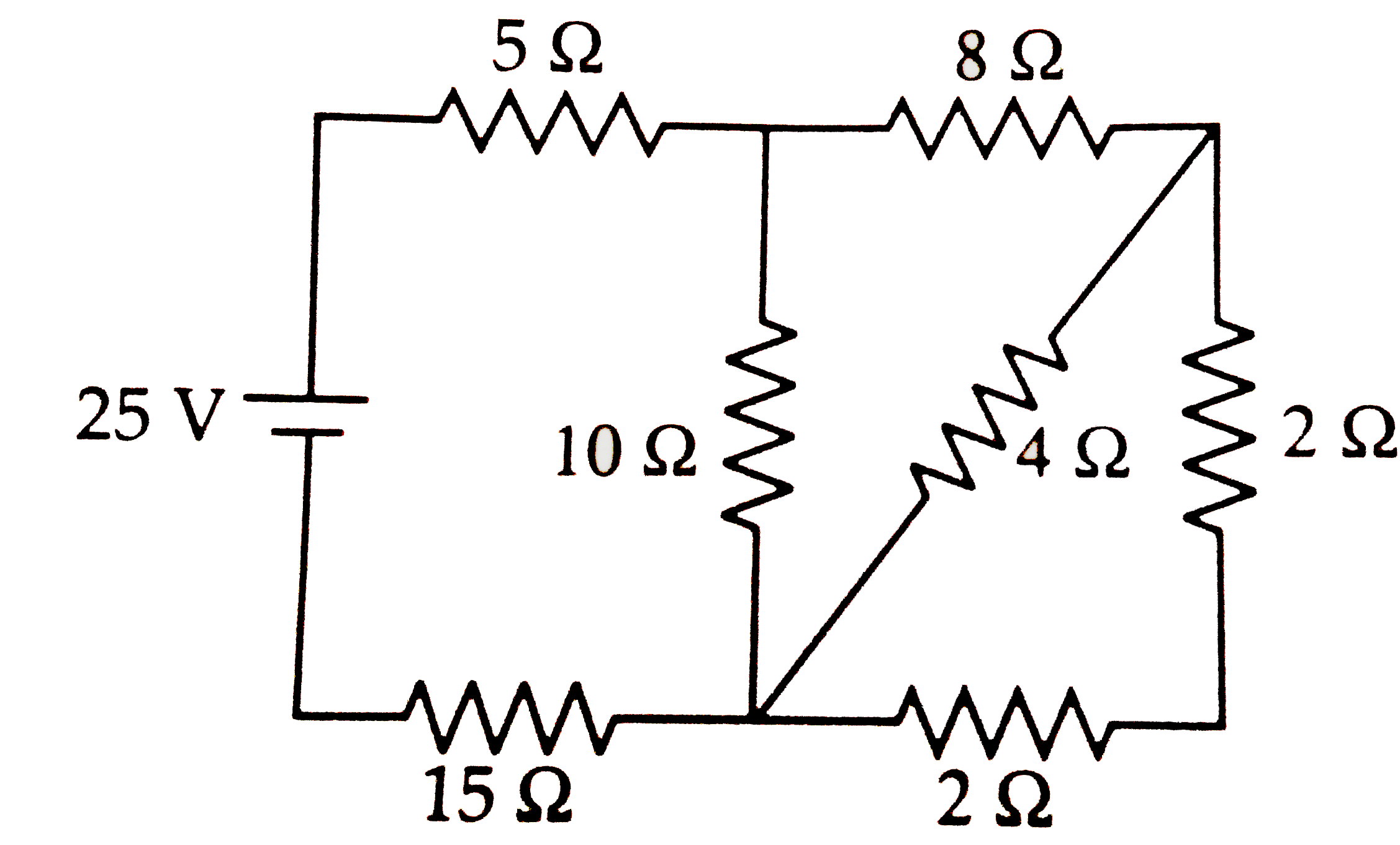 A0.5AB0.25AC1AD1.5A
For the circuit shown in the figure, find the charge stored on capacitor in steady state.
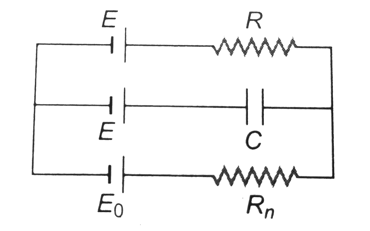 ARCR+R0EBRCR0E−E0CzeroDRCR+R0(E−E0)
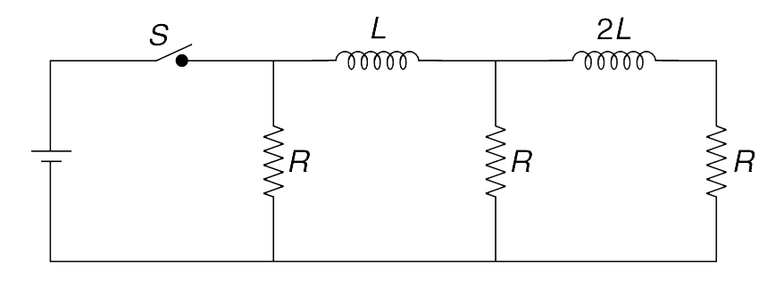
In the circuit shown in figure, the current through each resistor is I. Find the currents through the resistors immediately after the switch ‘S’ is opened. How much heat will get dissipated in the circuit after thw switch is opened ?
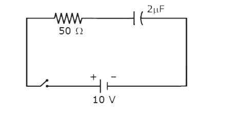
View SolutionFor the circuit shown in figure below, At t = 0, switch is closed, the initial current through resistor and final charge on capacitor are
View SolutionFor the circuit shown in figure, find the voltage acrss 10Ω resistor and the current passing through it.

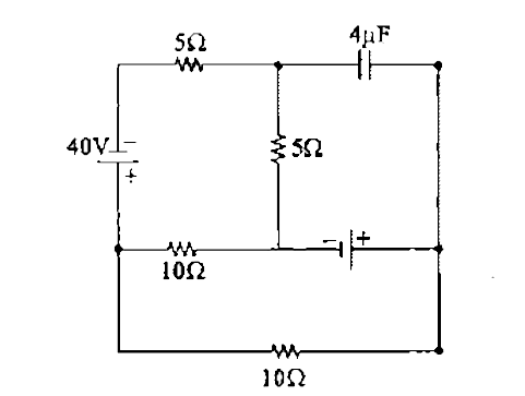
View SolutionIn the circuit shown in figure 3.141, find the energy stored in 4μF capacitor in steady state.
View SolutionIn the circuit shown in figure, time constant and steady state current will be
View Solution

