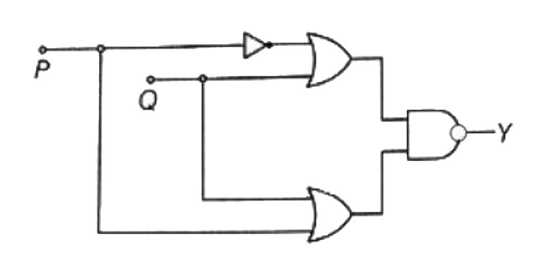
Let inputs of p and q be 1 and 0 respectively in electric circuit . Then output of p∧q is
1
0
Both 1 and 0
Neither 1 nor 0
The correct Answer is:B
We know that p∧q=0
Topper's Solved these Questions
Similar Questions
Let p and q be the position vectors of P and Q respectively with respect to O and |p|=p,|q|=q. The points R and S divide PQ internally and externally in the ratio 2 : 3 respectively. If −−→OR and −−→OS are perpendicular, then (A) 9p2=4q2 (B) 4p2=9q2 (C) 9p=4q (D) 4p=9q
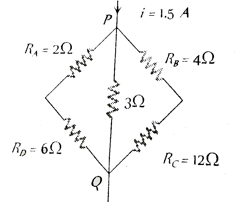
View SolutionThe equivalent resistance across P and Q in the given electric circuit will be

View Solution
Knowledge Check
Let →pand→q be the position vectors of the point P and Q respectively with respect to origin O. The points R and S divide PQ internally and externally respectiely in the ratio 2:3. If −−→ORand−−→OS are perpendicular, then which one of the following is correct?
A9p2=4q2B4p2=9q2C9p=4qD4p=9qLet C1 and C2 be respectively, the parabolas x2=y=−1 and y2=x−1 Let P be any point on C1 and Q be any point on C2 . Let P1 and Q1 be the refelections of P and Q, respectively with respect to the line y=x.
Arithemetic mean of PP1and QQ1 is always less thanAPQB12PQC2PQD32PQIn the given circuit P and Q from the inputs. The output Y is
 AY=¯¯¯PBY=P¯¯¯QCY=P+QDY=¯¯¯Q
In the logic circuit shown in the figure, if input A and B are 0 to 1 respectively, the output at Y would be ‘x’
The value of x is _______

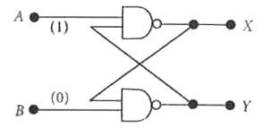
View SolutionIn the circuit shown, inputs A and B are in states '1' and '0' respectively. What is the only possible stable state of the outputs 'X' and 'Y'?

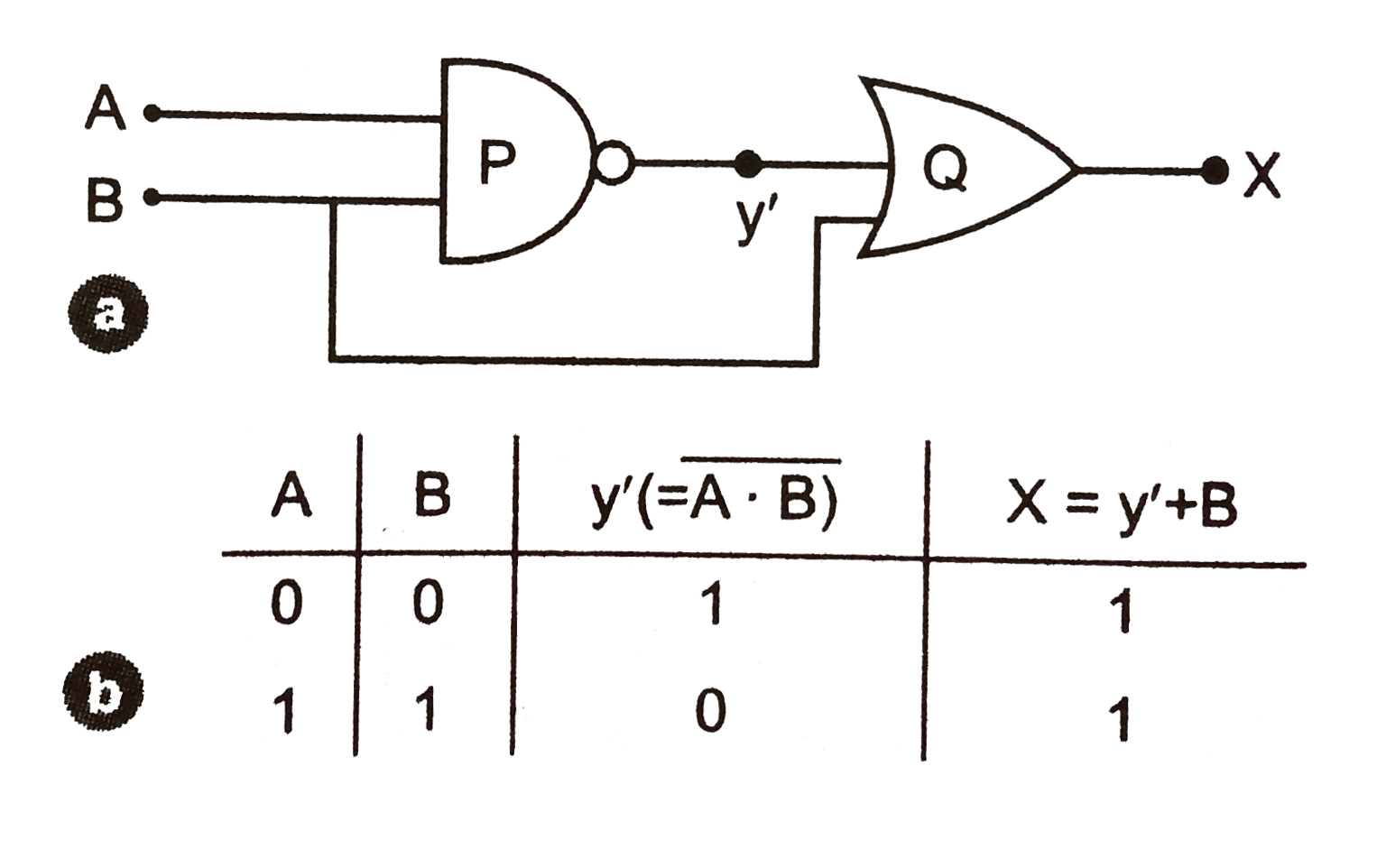
View SolutionIdentify the logic gates marked P and Q in the given logic circuit Fig. Write down then output at X for the inputs
(i) A=0,B=0 and (ii) A=1,B=1.

View SolutionLet C1 and C2 be respectively, the parabolas x2=y=−1 and y2=x−1 Let P be any point on C1 and Q be any point on C2 . Let P1 and Q1 be the refelections of P and Q, respectively with respect to the line y=x.
If the point p(π,π2+1) and Q(π2+1μ) then P1 and Q1 are
View SolutionPotential difference between the points P and Q in the electric circuit shown is

View Solution

