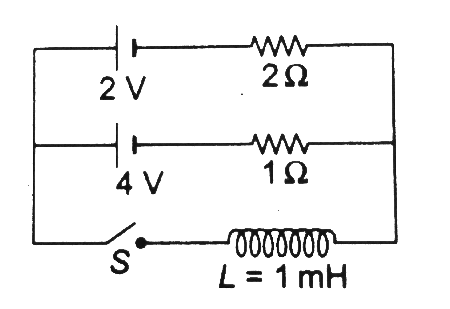
Level 1 Objective from DC PANDEY ENGLISH ELECTROMAGNETIC INDUCTION for Class 12
| Class 12 | PHYSICS |
| Chapter | ELECTROMAGNETIC INDUCTION |
| DC PANDEY ENGLISH | Level 1 Objective |
| Medium | English |
| Academic Year | 2023-2024 |
Question 5
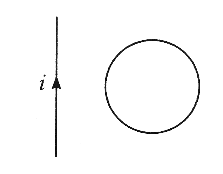
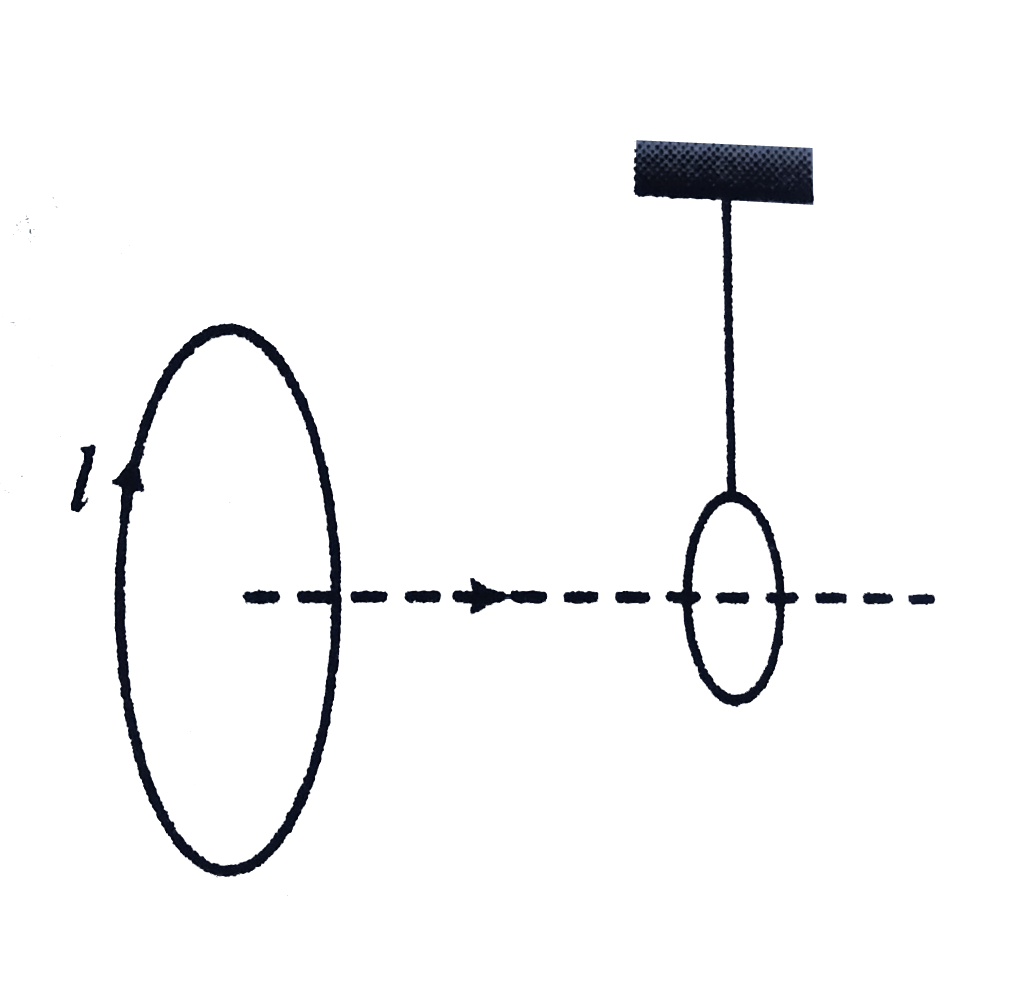
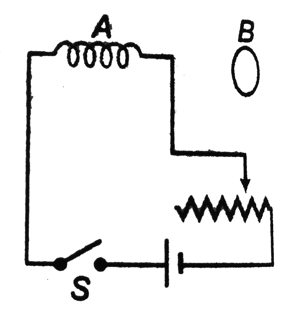
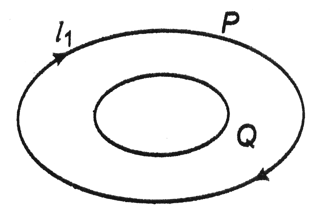
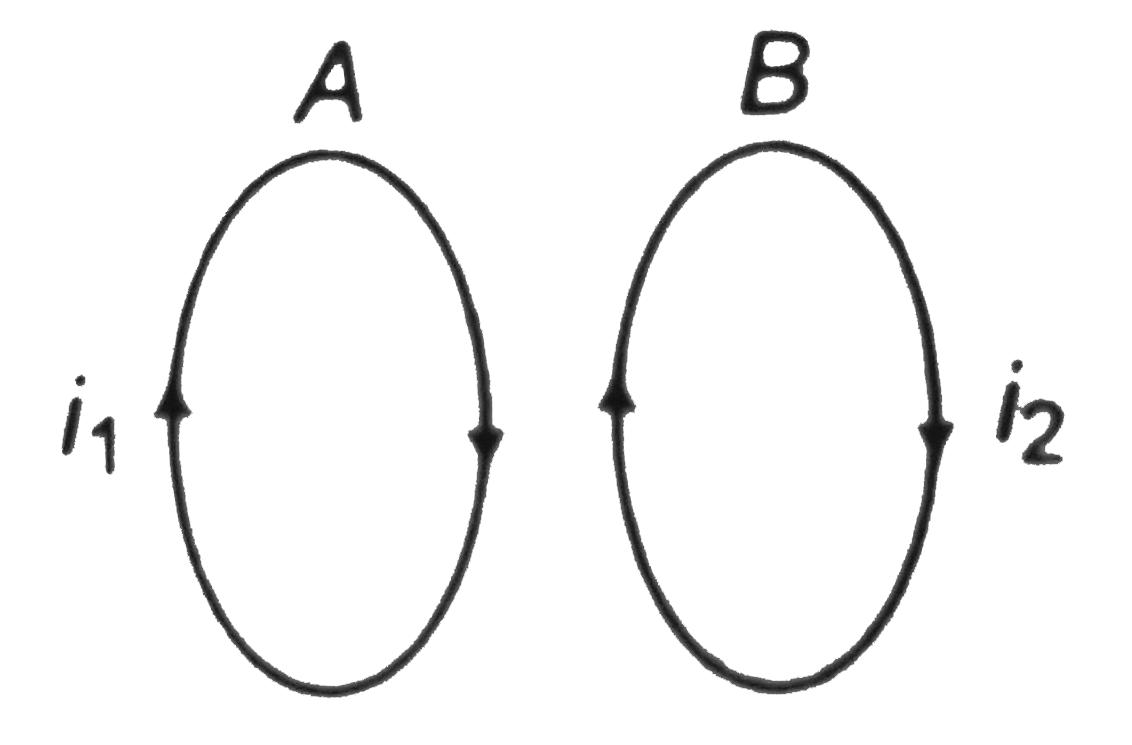
Two circular loops lie side by side in the same plane. One is connected to a source that supplies an increasing current, the other is a simple closed ring. Is the induced current in the ring is in the same direction as that in the loop connected to the source or opposite? What if the current in the first loop is decreasing? View SolutionQuestion 10
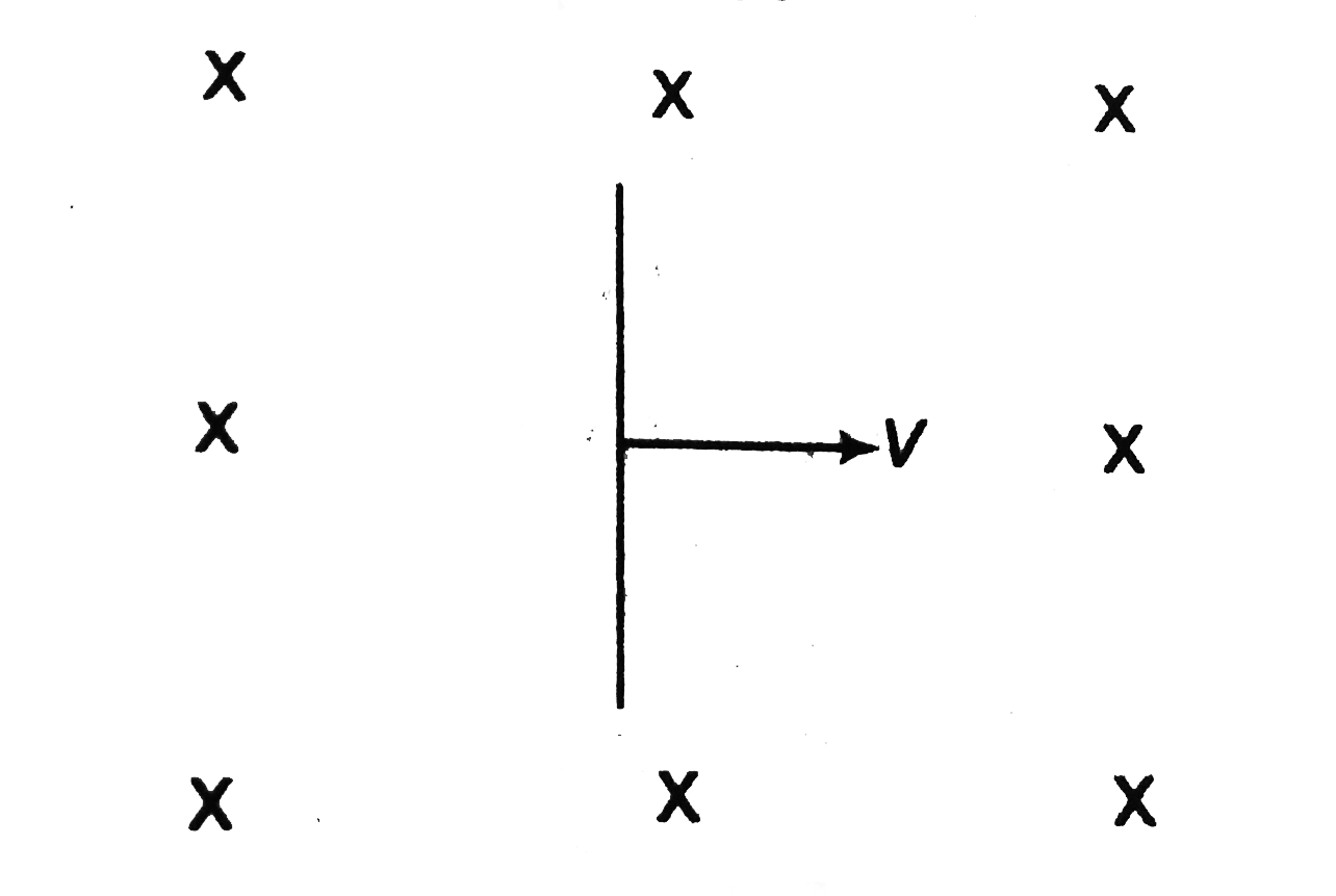
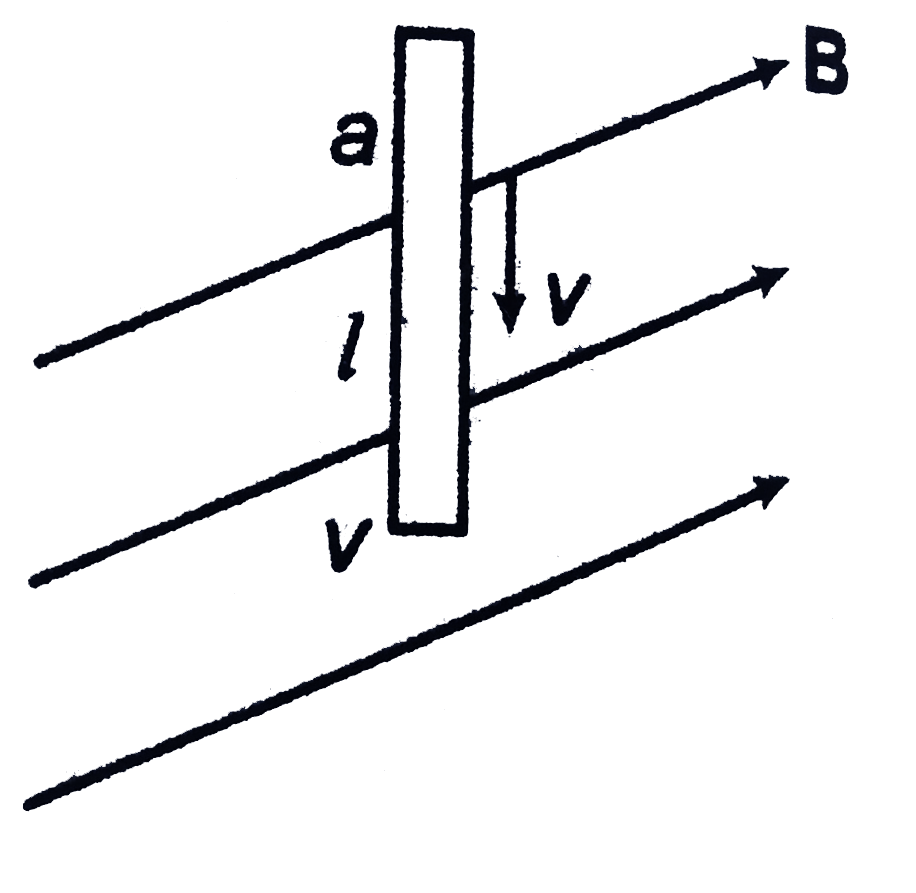
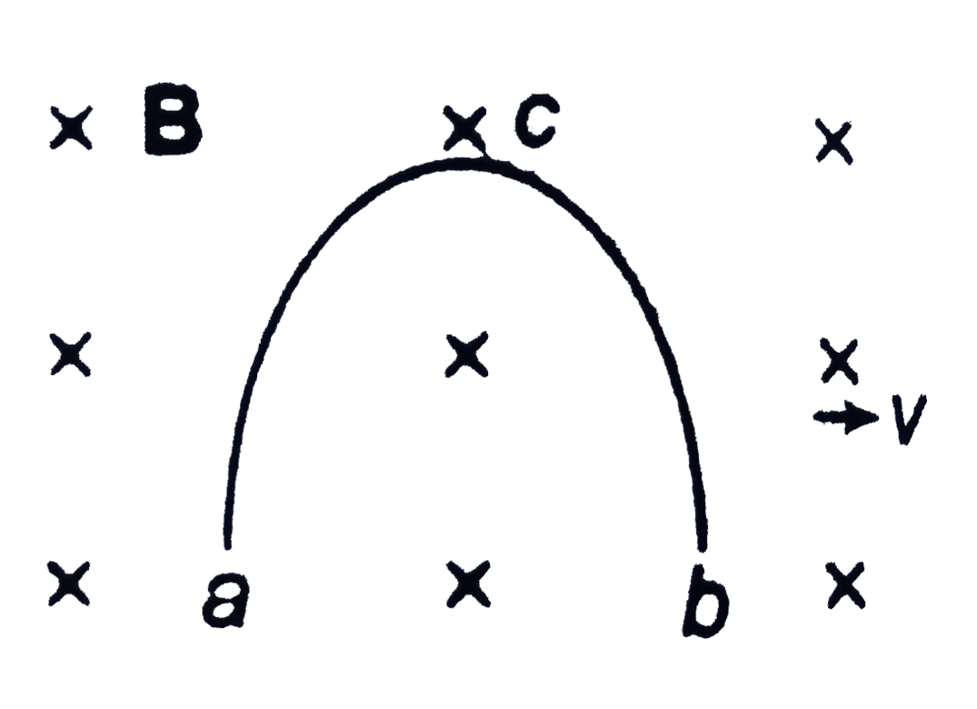
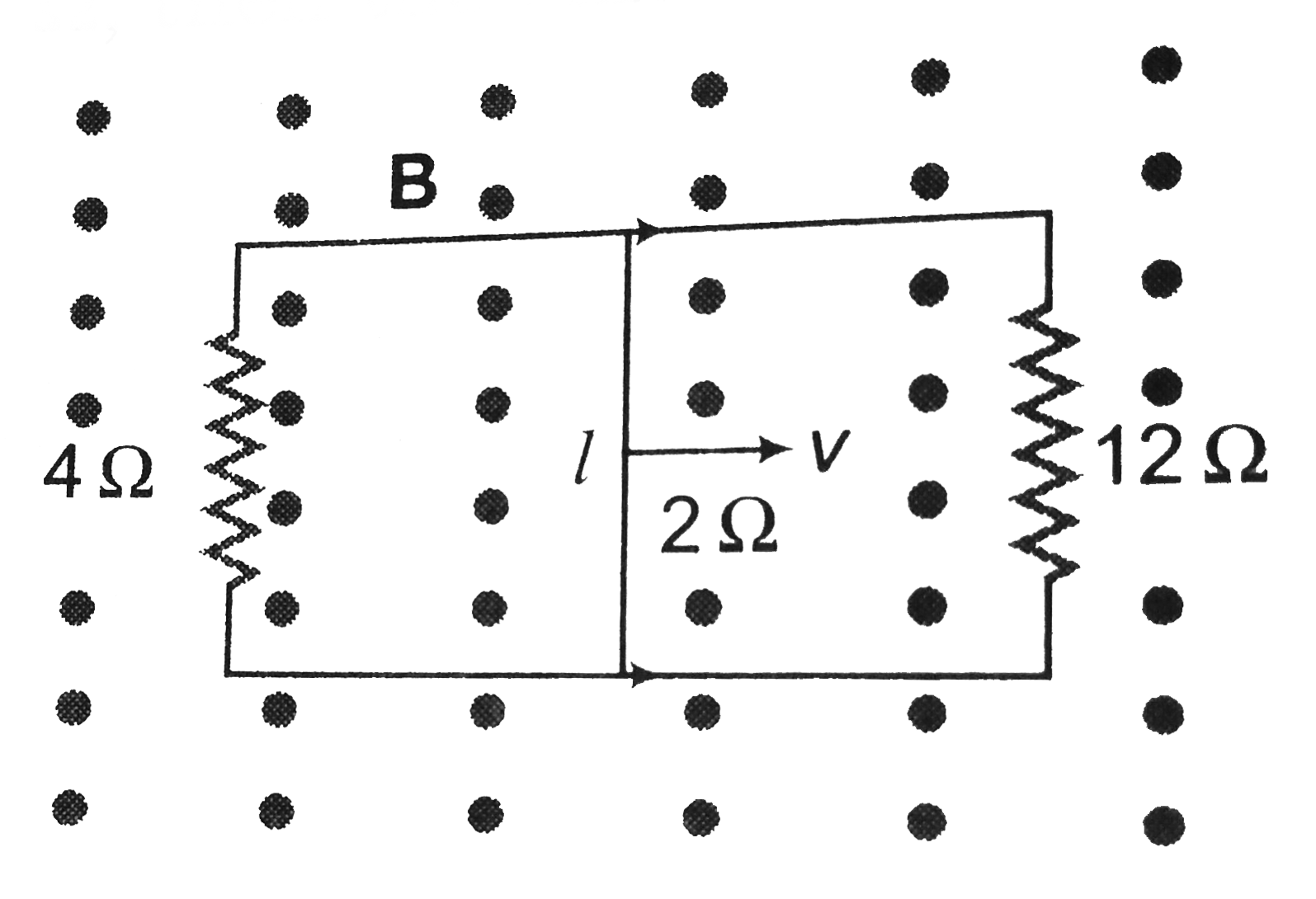
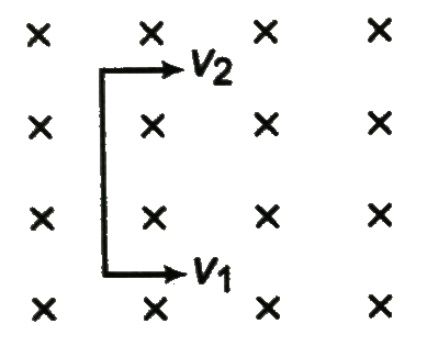
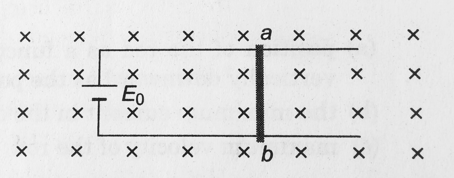
As shown in the figure, a metal rod makes rod makes contact with a particl circuit and completes the circuit. The circuit area is perpendicular ot a magneitc field with B = 0.15 T. If the resistance of the total circuit is 3Ω, the force needed to move the rod as indicated with a constant speed of 2ms−1 will be equal to
 View Solution
Question 16
(a) Calculate the self-inductance of a solenoid that is tightly wound with wire of diameter 0.10cm, has a cross-sectional area 0.90cm2 and is 40cm long
(b) If the current through the solenoid decreases uniformly from 10 A to 0A in 0.10s, what is the emf induced between the ends of the solenoid? View SolutionQuestion 18
A coil has 600 turns which produces 5×10⁻³Wb/turn of flux when 3A current flows in the wire. This produced 6×10⁻³ Wb/turn in 1000 turns secondary coil. When the opened, the current drops to zero in 0.2s in primary. Find
(a) mutual inductance,
(b) the induced emf in the secondary,
(c) the self-inductance of the primary coil. View SolutionQuestion 19
Two coils have mutual inductance M=3.25×10⁴H. The current i1 in the ffrst coil increases at a uniform rate of 830A/s.
(a) What is the magnitude of the induced emf in the second coil? Is it constant?
(b) Suppose that the current described is in the second coil rather than the first. What is the induced emf in the first coil?View SolutionQuestion 21
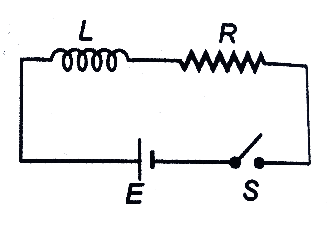
A coil of inductance 2H and resistance 10Ω are in a series circuit with an open key and a cell of constant 100V with negligible resistance. At time i=0, the key is closed. Find
(a) the time constant of the circuit.
(b) the maximum steady current in the circuit.
(c) the current in the circuit at f=1s.View SolutionQuestion 27
A long solenoid of cross-sectional area 5.0cm2 is wound with 25 turns of wire per centimetre. It is placed in the middle of a closely wrapped coil of 10 turns and radius 25 cm as shown.
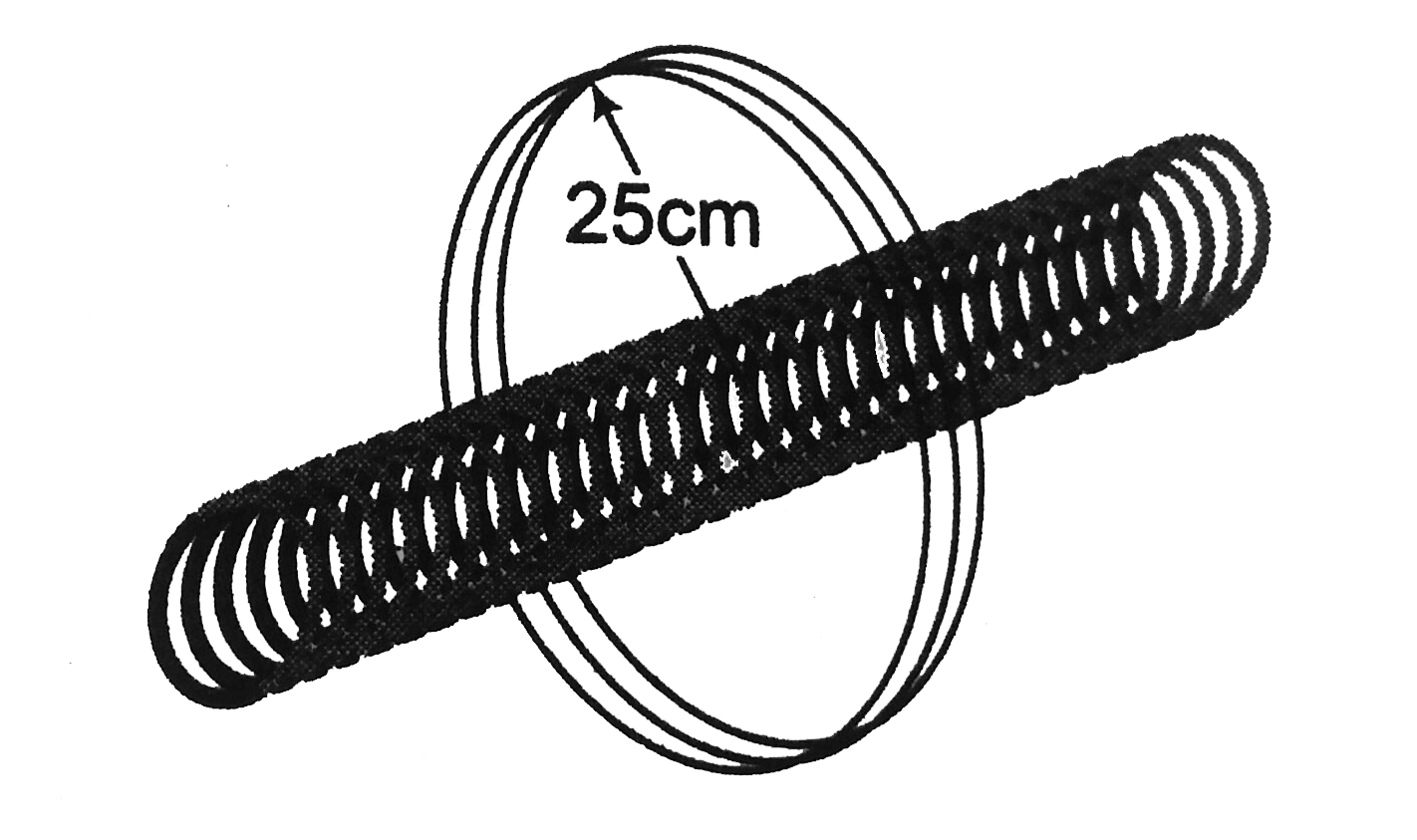
(a) What is the emf induced in the coil when the current through the solenoid is decreasing at a rate −0.20A/s ?
(b) What is the electric field induced in the coil? View SolutionQuestion 28
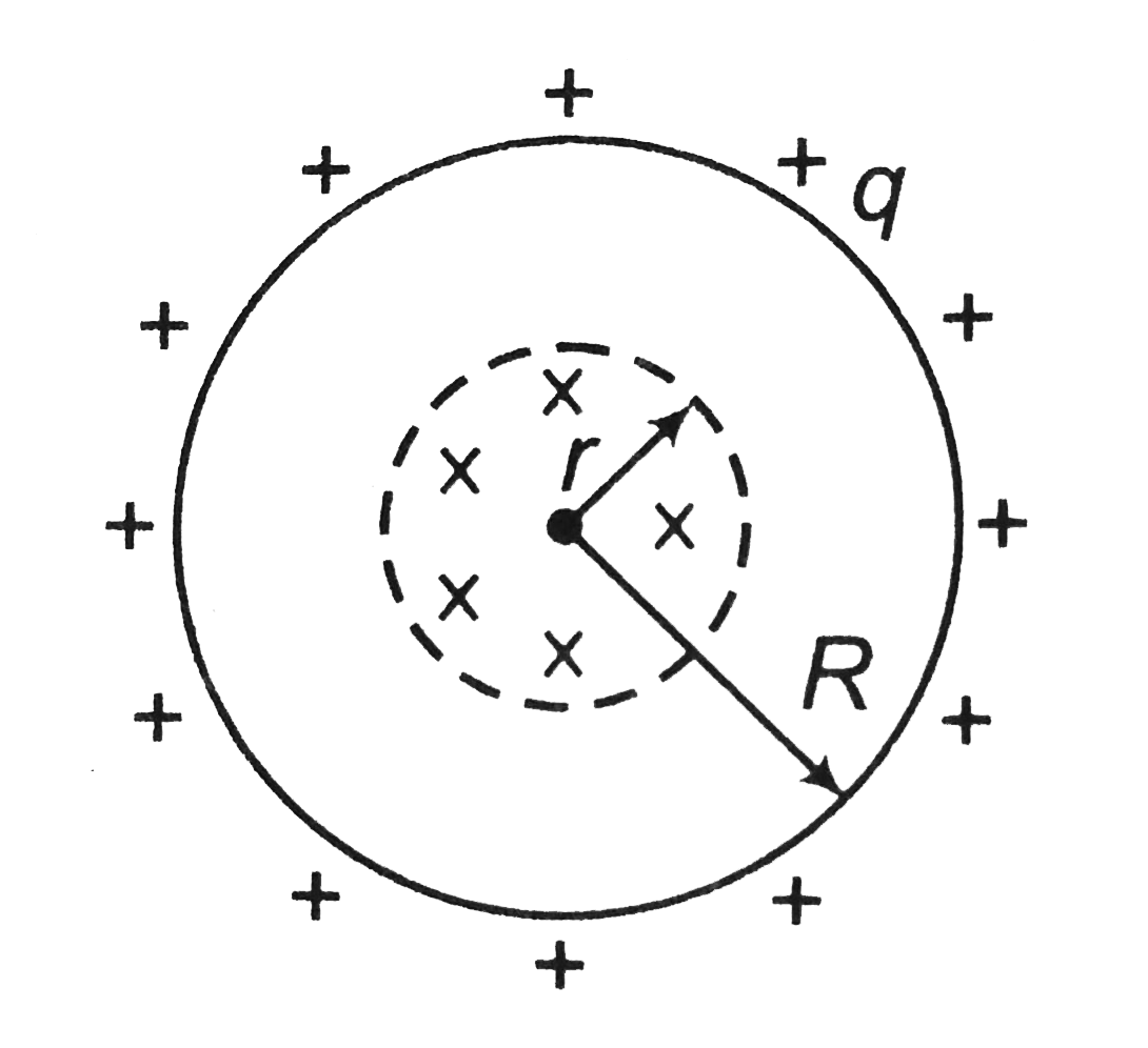
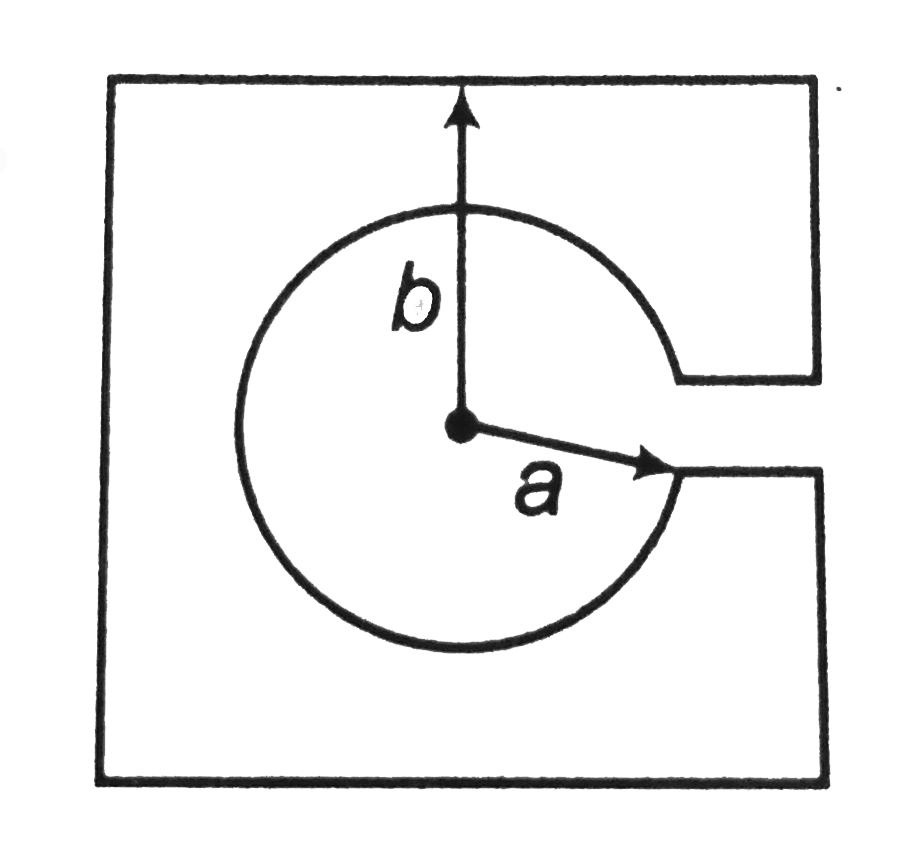
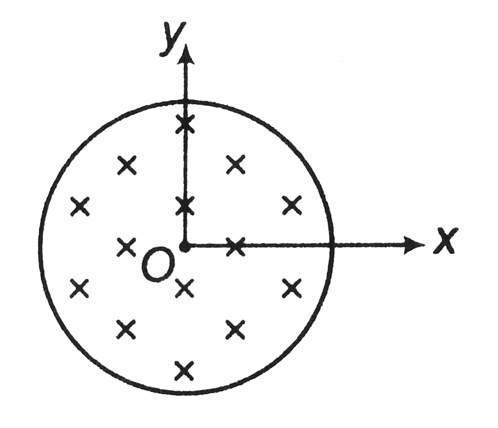
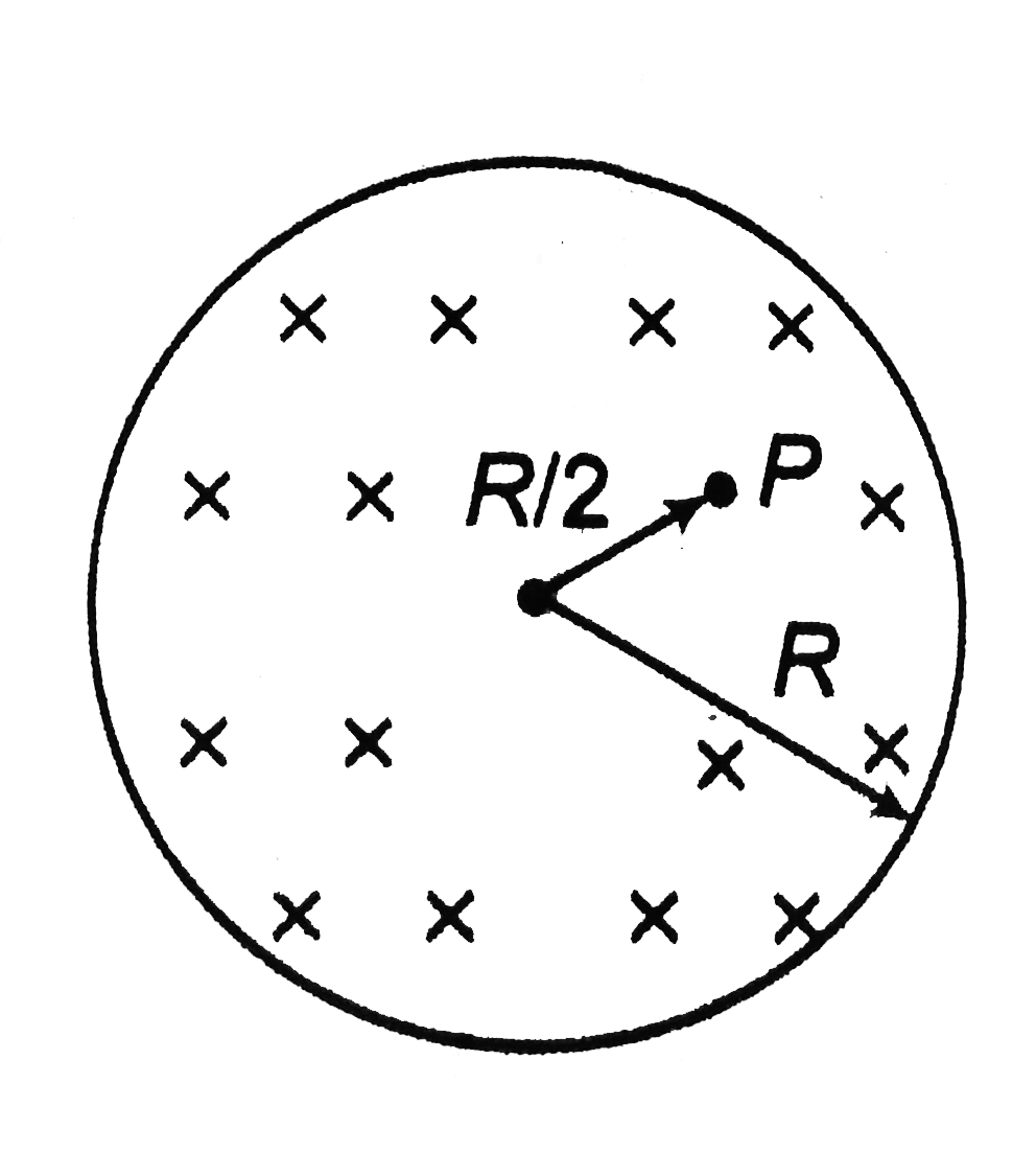
For the situation described in figure, the magnetic field changes with time according to
B=(2.00t3−4.00t2+0.8)t and r2=2R=5.0cm
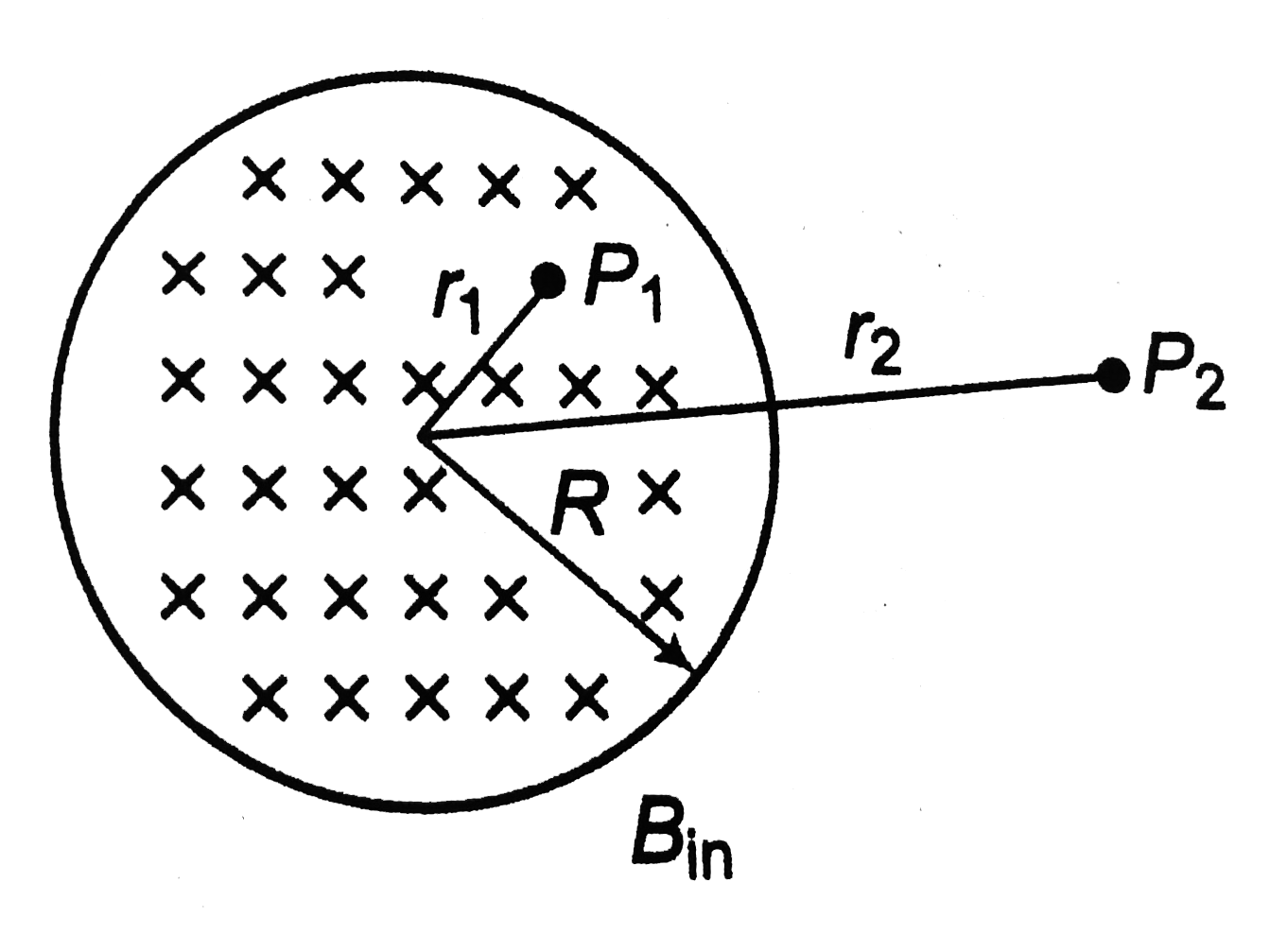
(a) Calculate the force on an electron located at P2 at t=2.00s
(b) What are the magnitude and direction of the electric field at P1 when t=3.00s and r1=0.02m. View SolutionQuestion 68
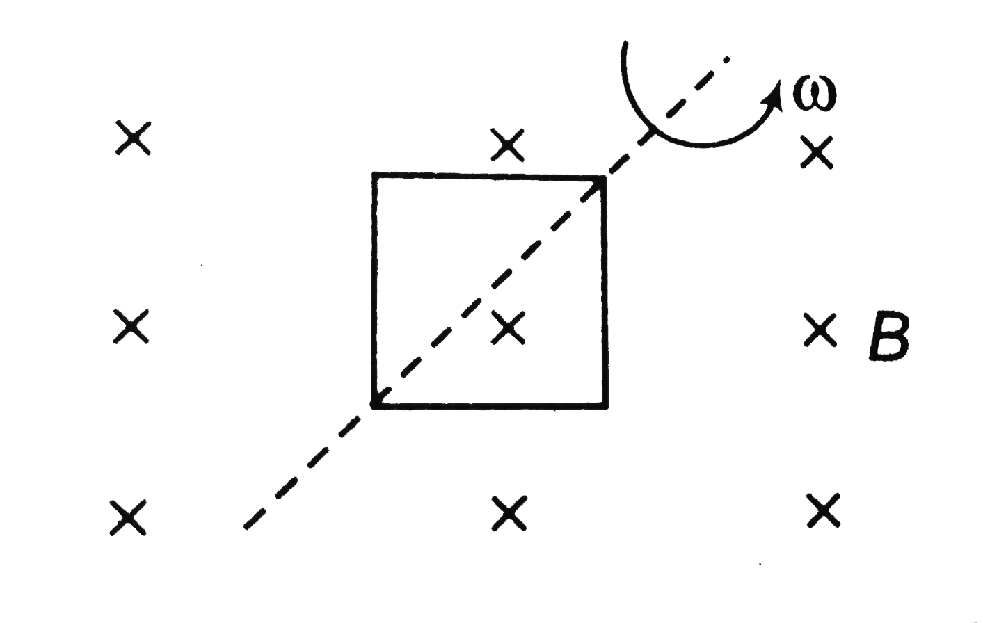
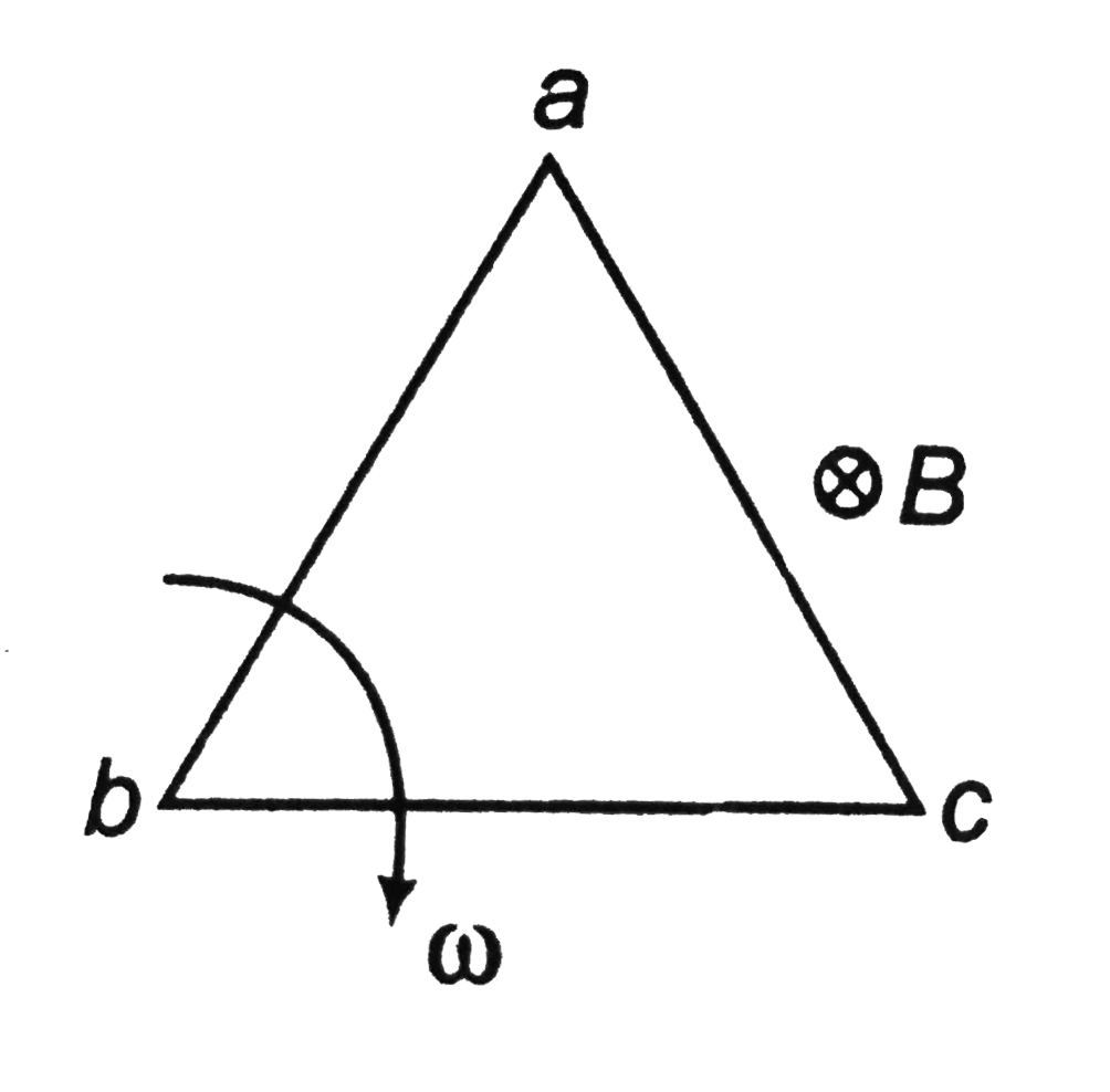
A flat circular coil of n turns, area A and resitance R is placed in a uniform magnetic field B. The pane of coil is initially perpedicular of B. when the coil is rotated through an angle of 180∘ about one of its diameter, a charge Q1 flows through the coil When the same coil after charge Q2 flows through it. then Q2/Q1 isView SolutionQuestion 77
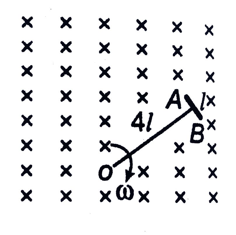
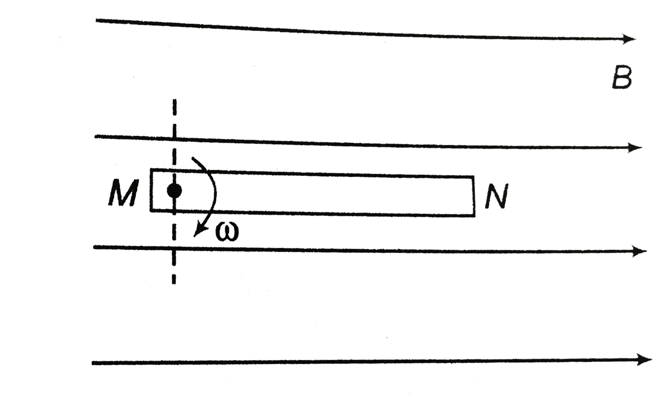
A metallic rod of length l is hinged at the point M and is rotating about an axis perpendicular to the plane of paper with a constant angular velocity ω. A uniform magnetic field of intensity B is acting in the region (as shown in the figure) parallel to the plane of paper. The potential difference between the points M and N
 View Solution
Question 79
A coil formed by wrapping 50 turns of wire in the shape of a square is positioned in a magnetic field so that the normal to the plane of the coil makes an angle of 30∘. with the direction of the field. When the magnetic field is increased uniformly from 200μT to 600μT in 0.4s, an emf of magnitude 80.0 mV is induced in the coil. What is the total length of the wire? View SolutionQuestion 80
A loop of wire enclosing an area S is placed in a region where the magnetic field is perpendicular to the plane. The magnetic field B varies with time according to the expression B=B0e−at where a is some constant. That is, at t=0. The field is B0 and for t>0, the field decreases exponentially. Find the induced emf in the loop as a function of time.View SolutionQuestion 81
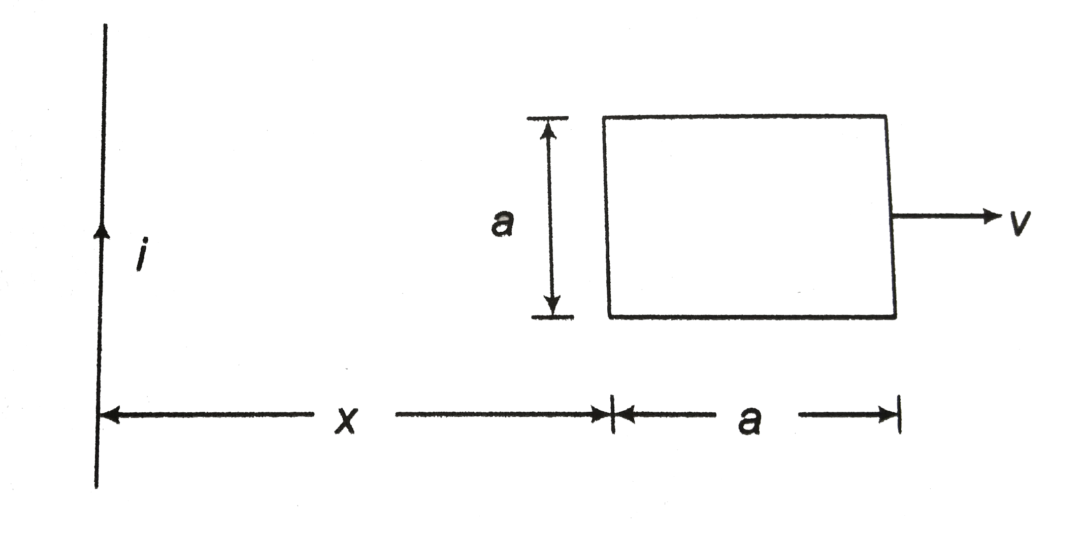
The long straight wire in figure (a) carries a constant current i. A metal bar of length i is moving at constant velocity v as shown in figure. Point a is a distance d from the wire.
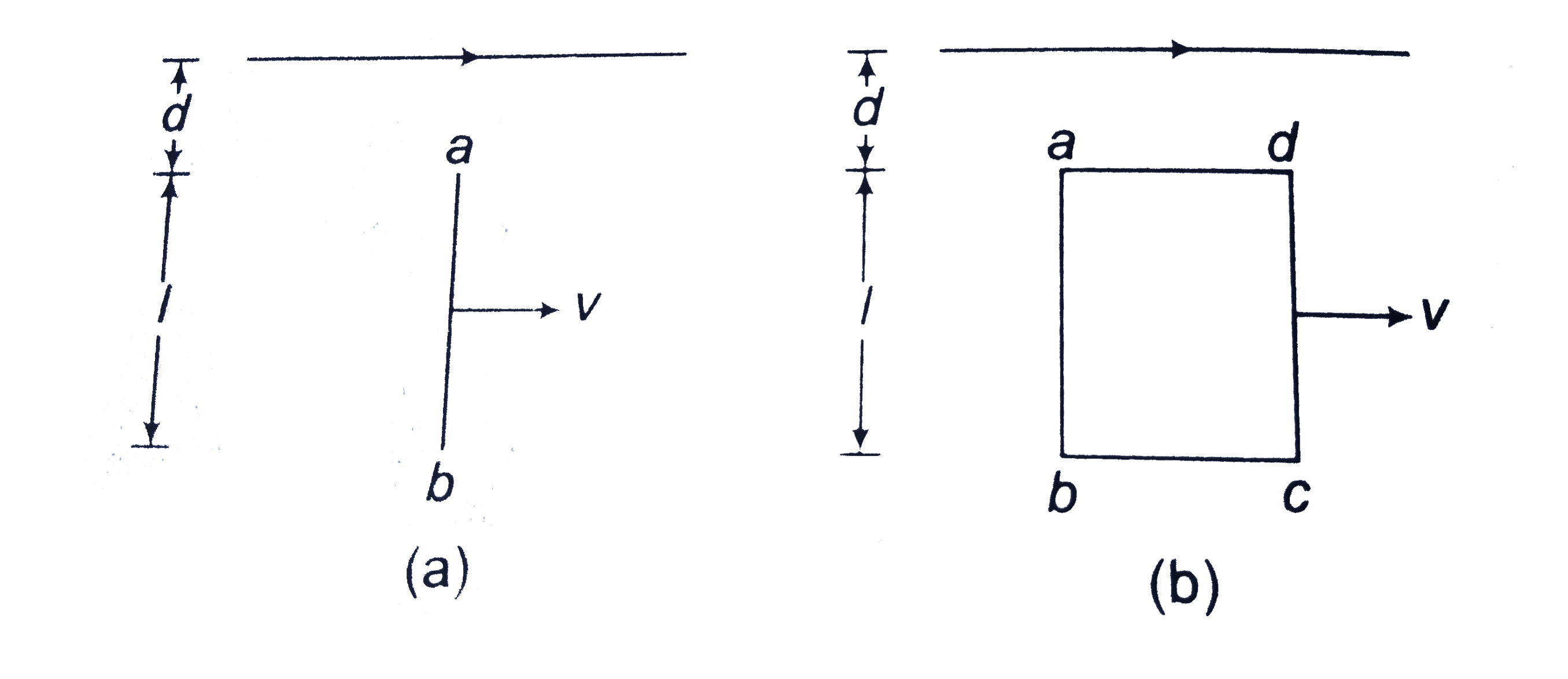
(a) Calculate the emf induced in the bar.
(b) Which point a or b is at higher potential?
(c) If the bar is replaced by a rectangular wire loop of resistance R, what is the magnitude of current induced in the loop? View SolutionQuestion 83
A small coil is introduced between the poles of an electromagnet so that its axis coincides with the magnetic field direction. The cross-sectional area of the coil is equal to S=3.0mm2, the number of turns is N=60. When the coil turns through 180∘ about its diameter, a galvanometer connected to the coil indicates a charge q=4.5μC flowing through it. Find the magnetic induction magnitude between the poles, provided the total resistance of the electric circuit equals R=40Ω. View SolutionQuestion 84
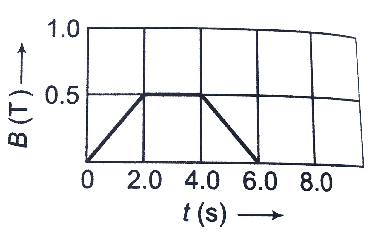
The magnetic field through a single loop of wire, 12cm in radius and of 8.5Ω resistance, changes with time as shown in figure. Calculate the emf in the loop as a function of time. Consider the time intervals
(a) t=0 to t=2.0s (b) t=2.0s to t=4.0s (c) t=4.0s to t=6.0s.
The magnetic field is perpendicular to the plane of the loop.
 View Solution
Question 85
A square loop of wire with resistance R is moved at constant speed v across a uniform magnet field confined to a square region whose sides are twice the lengths of those of the square loop
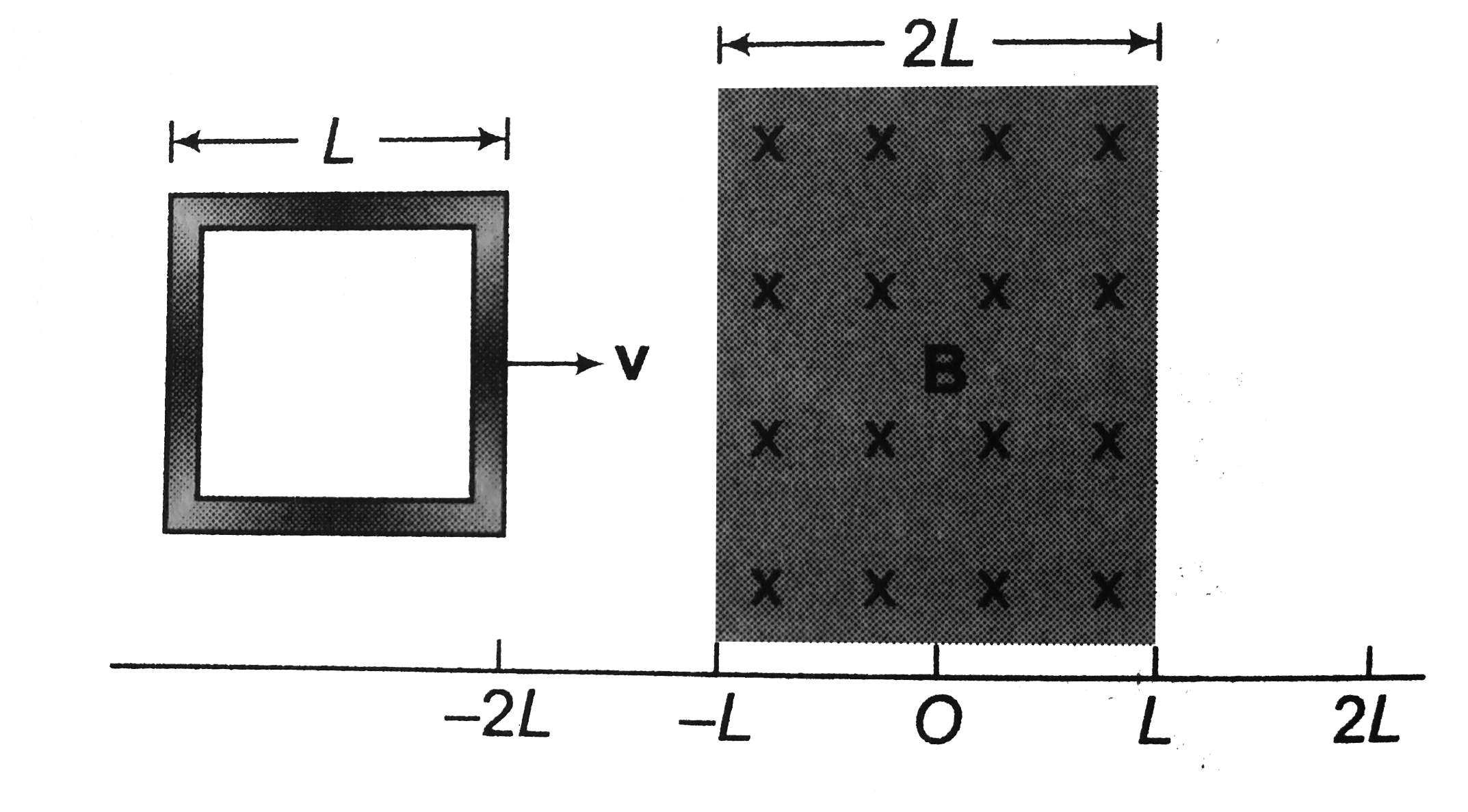
(a) Sketch a graph of the external forces F needed to move the loop at constant speed, as a function of to sketch a graph of the external force F need tho coordinate x, fromx=−2L to x=+2L. (The coordinate x is measured from the centre of the oignetic field region to the centre of the loop. It is negative when the centre of the loop is to the left, of the centre of the magnetic field region. Take positive force to be to the right). (b) Sketch a graph of the induced current in the loop as a function of x. Take counterclockwise currents to be positive. View SolutionQuestion 89
At the instant when the current in an inductor magnitude of the self-induced emf is 0.0640A/s, the magnitude fo the self- induced emf is 0.0160V.
(a) What is the inductance of the inductor?
(b) If the inductor is a solenoid with 400 turns, what is the average magnetic flux through each turn when the current is 0.720A?View SolutionQuestion 90
Two toroidal solenoids are wound around the same pipe so that the magnetic field of one passes through the turns of the other. Solenoid 1 has 700 turns and solenoid 2 has 400 turns. When the current in solenoid 1 is 6.52A, the average flux through each turn of solenoid 2 is 0.0320Wb.
(a) What is the mutual inductance of the pair of solenoids?
(b) When the current in solenoid 2 is 2.54A, what is the average flux through each solenoid 1? View SolutionQuestion 92
A 3.56H inductor is placed in series with a 12.8Ω resistor. An emf of 3.24V is then suddenly applied across the RL combination.
(a) At 0.278s after the emf is applied what is the rate at which energy is being delivered by the battery?
(b) At 0.278s, at what rate is energy appearing as thermal energy in the resistor? (c) At0.278s, at what rate is energy being stored in the magnetic field?View SolutionQuestion 93
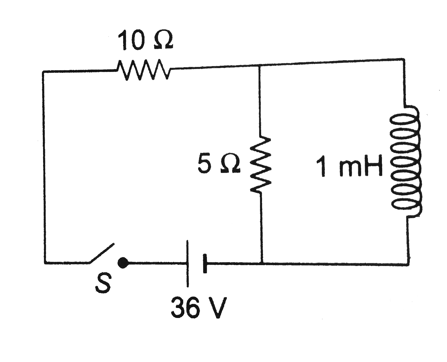
A 35.0V battery with negligible internal resistance, a 50.0Ω resistor, and a 1.25mH inductor with negligible resistance are all connected in series with an open switch. The switch is suddenly closed
(a) How long after closing the switch will the current through the inductor reach one-half of its maximum value?
(b) How long after closing the switch will the energy stored in the inductor reach one-half of its maximum value? View SolutionQuestion 94
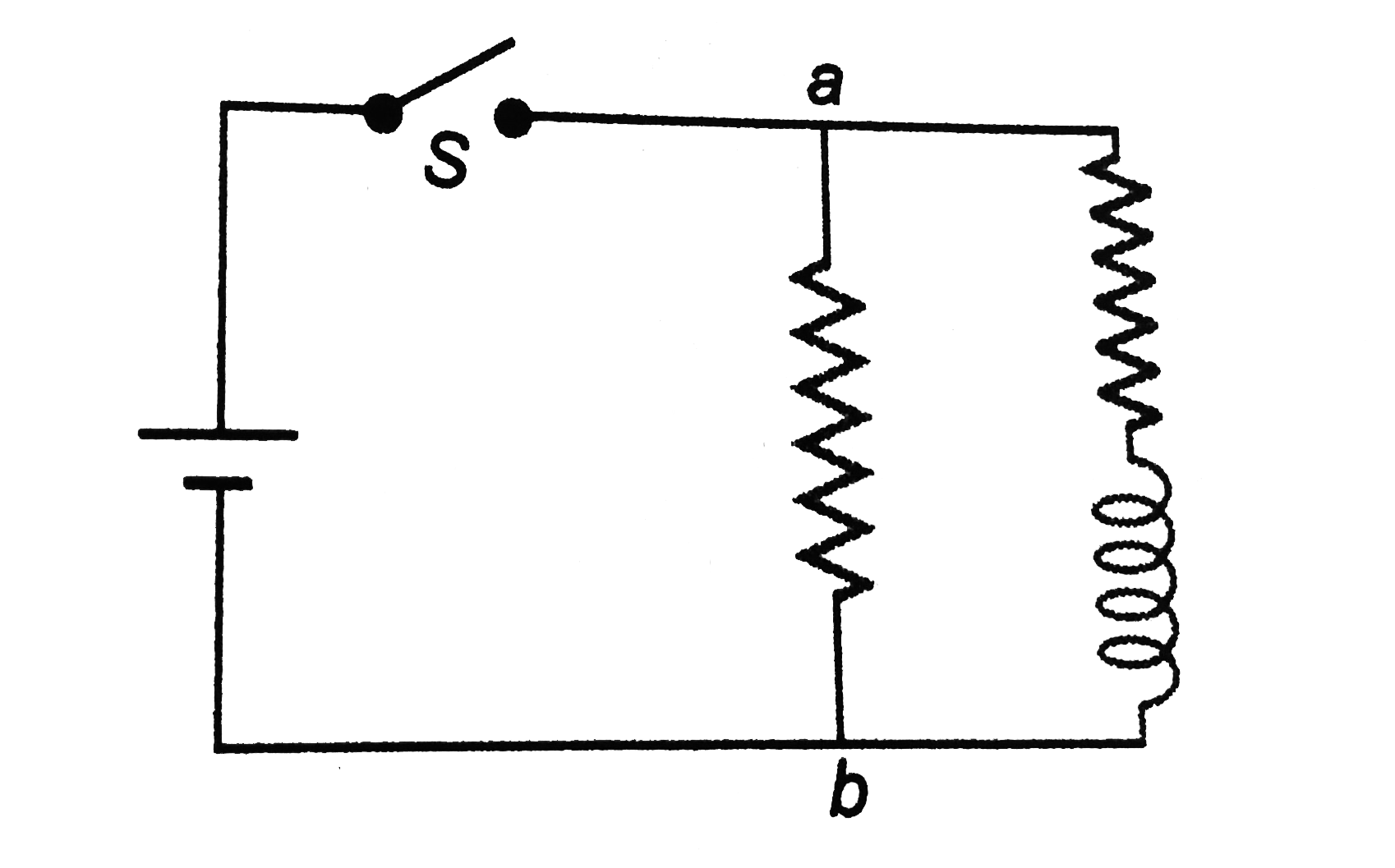
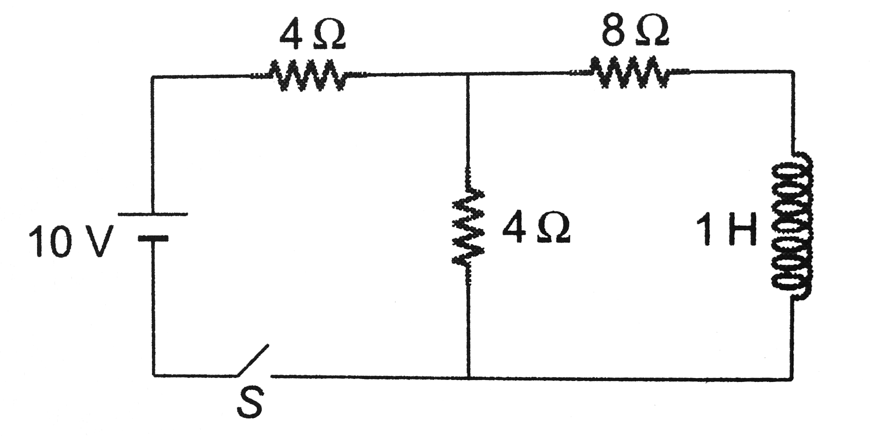
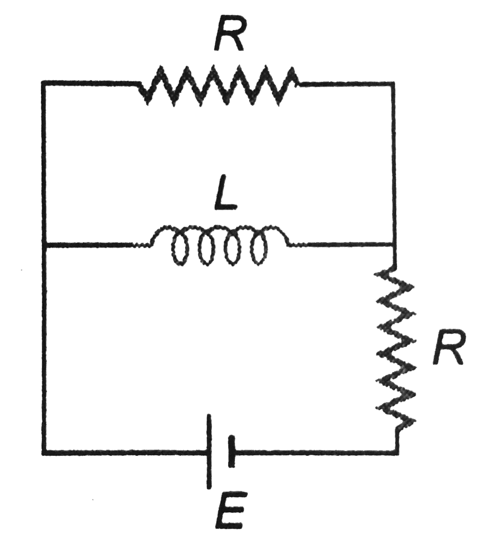
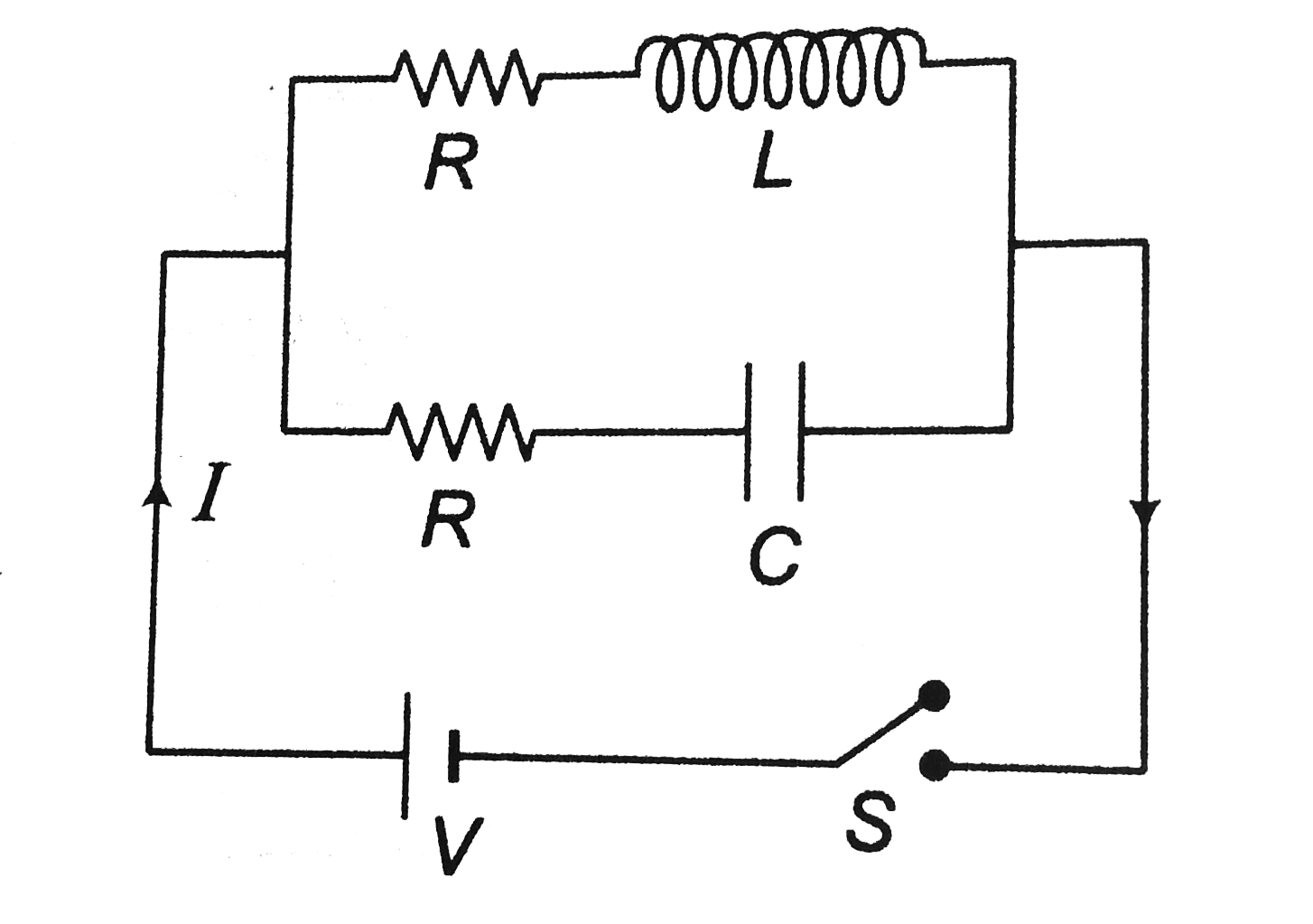
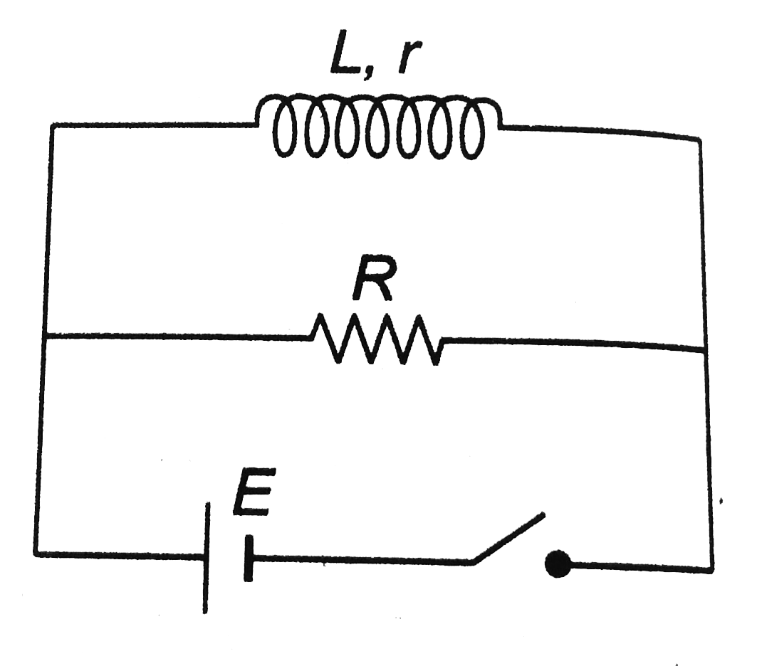
A solenoid of inductance L with resistance r is connected in parallel to a resistance R. A battery of emf E and of negligible internal resistance is connected across the parallel combination as shown in the figure. At time t=0, switch S is opened, calculate
(a) current through the solenoid after the switch is opened.
(b) amount of heat generated in the solenoid.
 View Solution
Question 96
In an oscillating L−C circuit in which C=4.00μF, the maximum potential difference capacitor during the oscillations is 1.50V and the maximum current through 50.0mA.
(a) What is the inductance L?
(b) What is the frequency of the oscillations?
(c) How much time does the charge on the capacitor take to rise from zero to its maximum value?View SolutionQuestion 97
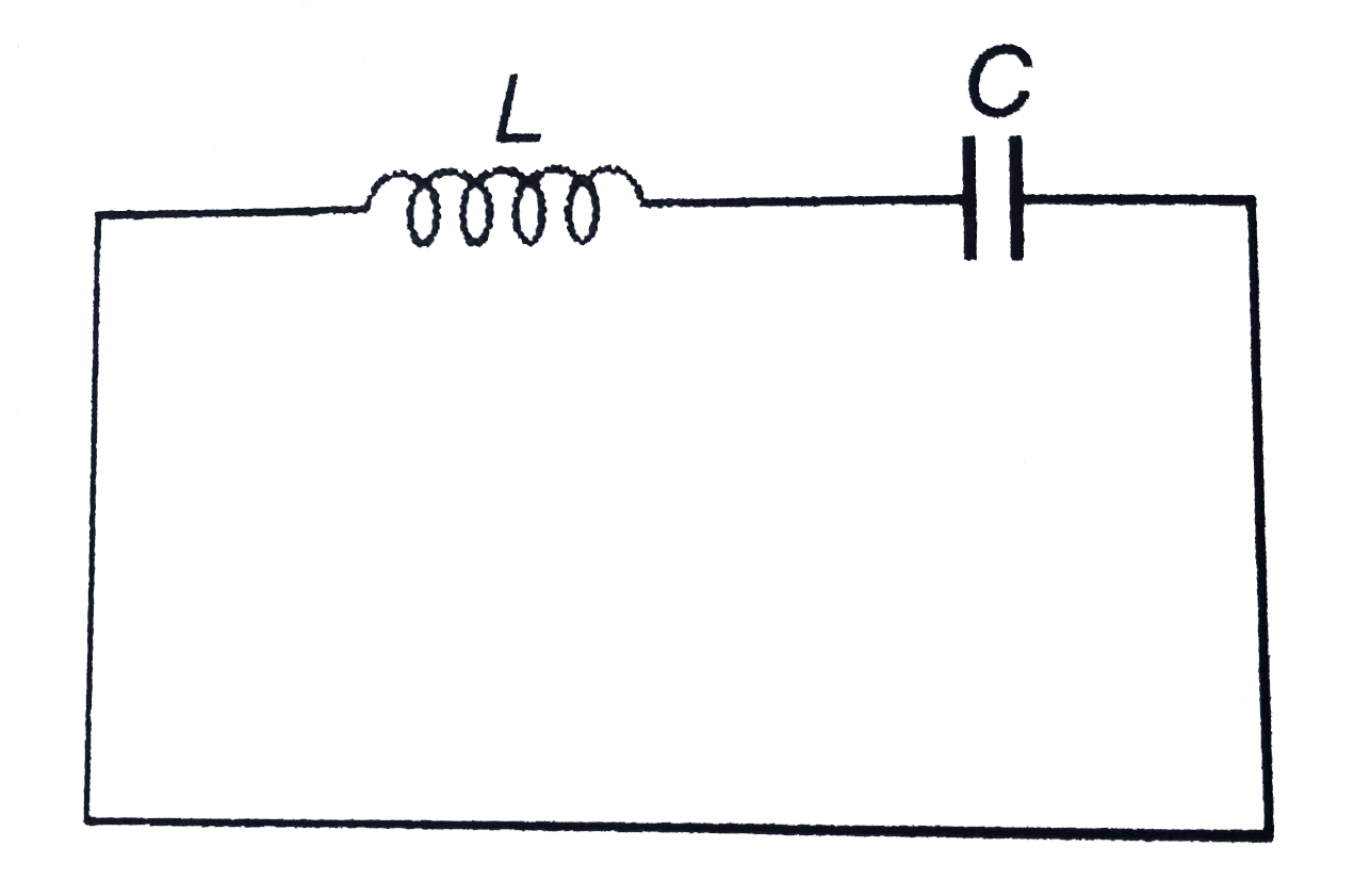
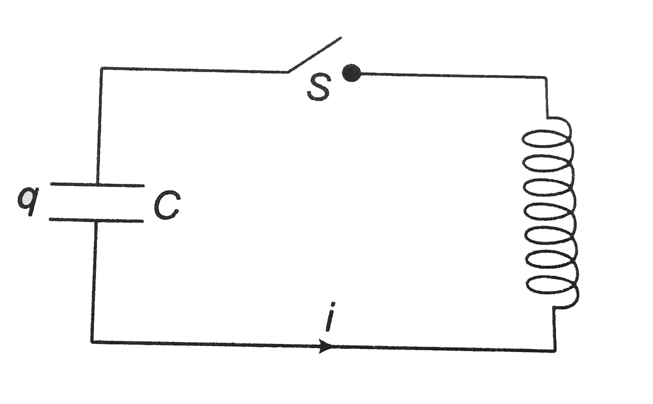
In the L−C circuit shown, C=1μF. With capacitor charged to 100V, switch S is suddenly closed at time t=0. The circuit then oscillates at 103Hz
(a) Calculate co and T
(b) Express q as a function of time
(c) Calculate L
(d) Calculate the average current during the first quarter-cycle.
 View Solution
Question 98
An L−C circuit consists of an inductor with L=0.0900H and a capacitor of C=4x10⁻⁴F. The initial charge on the capacitor is 5.00μC, and the initial current in the inductor is zero.
(a) What is the maximum voltage across the capacitor?
(b) What is the maximum current in the inductor?
(c) What is the maximum energy stored in the inductor?
(d) When the current in the inductor has half its maximum value, what is the charge on the capacitor and what is the energy stored in the inductor?View SolutionQuestion 99
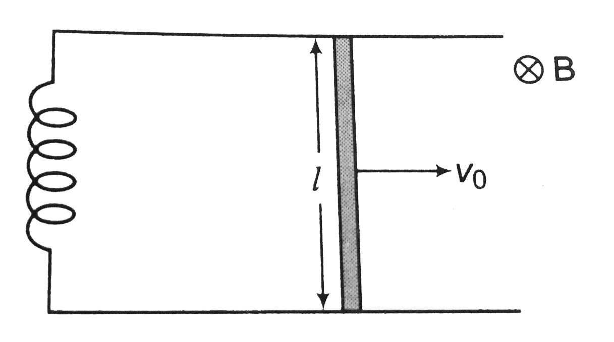
Two ends of an inductor of inductance L are connected to two parallel conducting wires. A rod of length l and mass m is gien velocity v0 as shown. The whole sytem is placed in perpendicular magnetic field B. Find the maximum current in the inductor. (Neglect gravity and friction)
 View Solution
Question 100
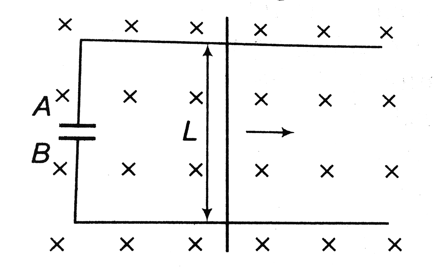
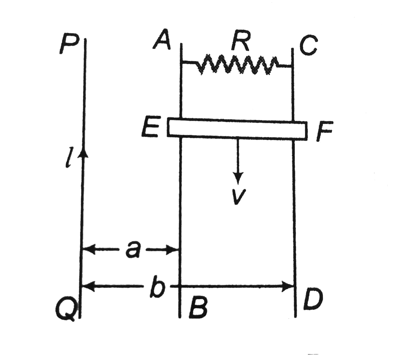
A conducting rod is moving with a constant velocity v over the parallel conducting rails which are connected at the ends through a resistor R and capacitor C as shown in the figure. Magnetic field B is into the plane. Consider the following statements.
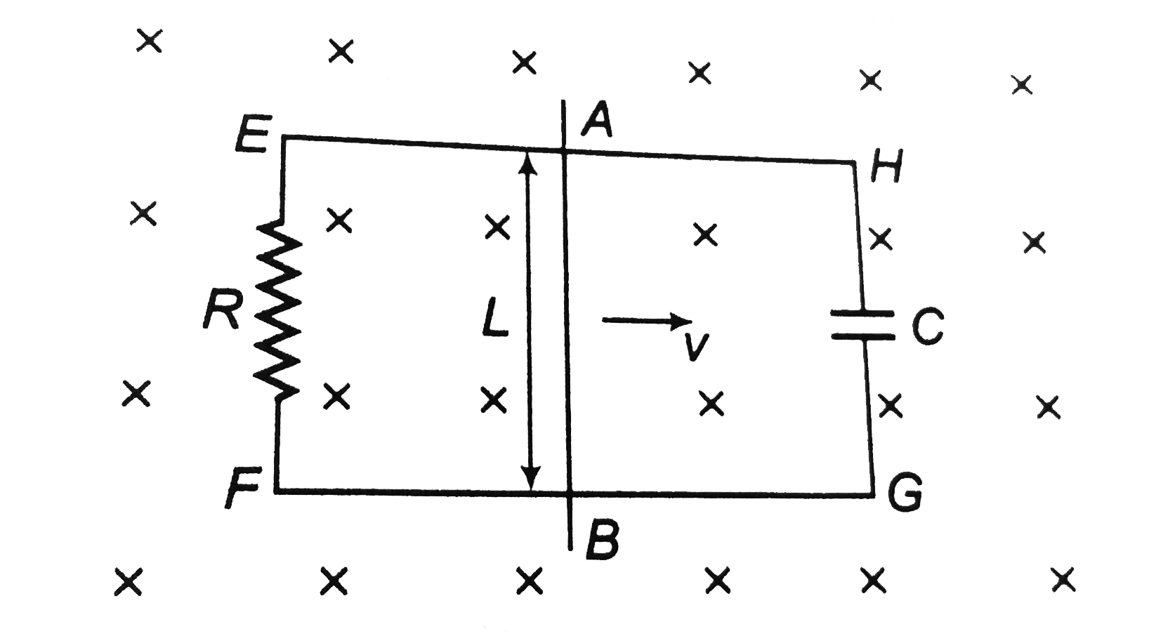
i. Current in loop AEFBA is anti clockwise
ii. Current in loop AEFBA is clockwise
iii Current through the capacitor is zero
iv Energy stored in the caspacitor is 12CB2L2v2
Which is the following options in correct?View SolutionQuestion 102
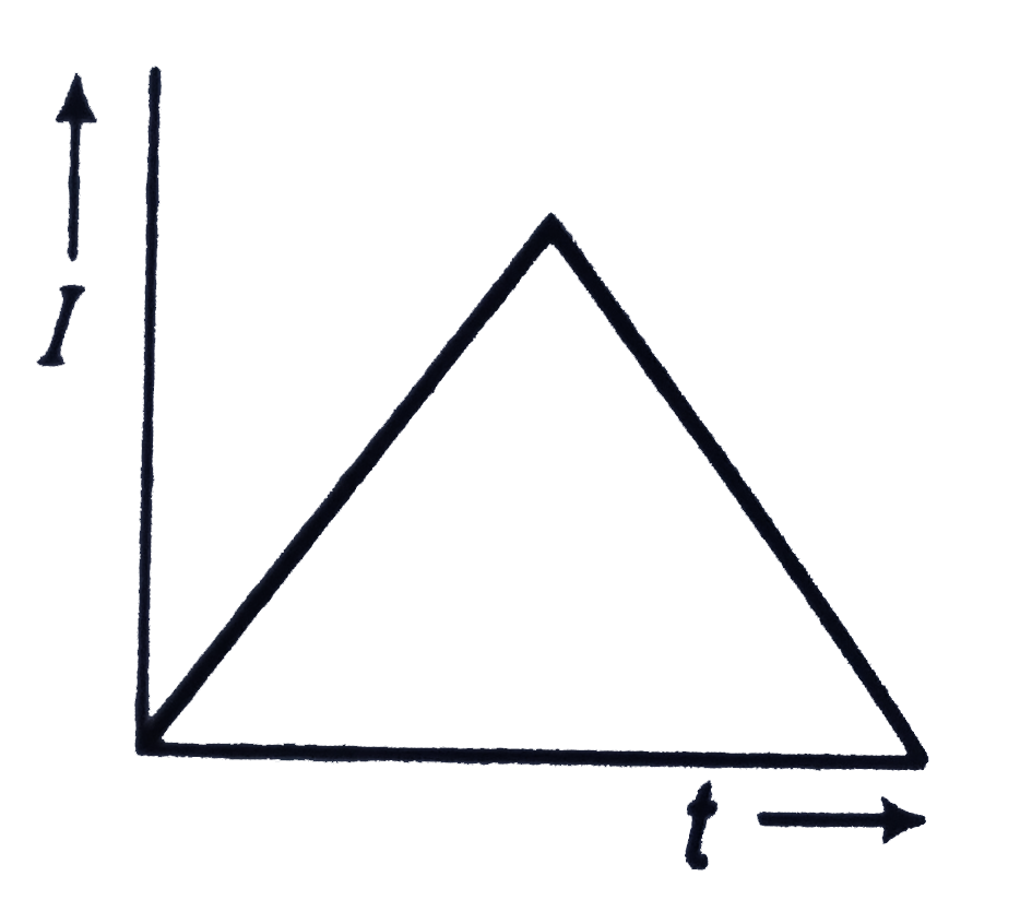
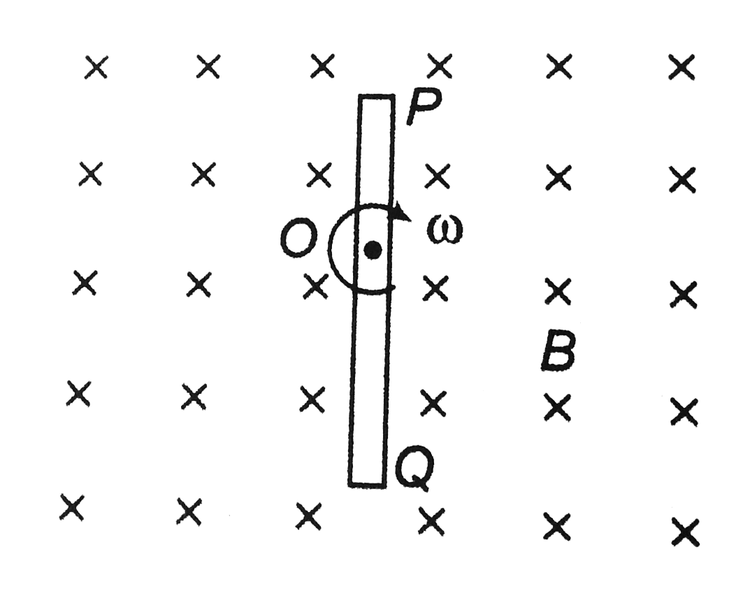
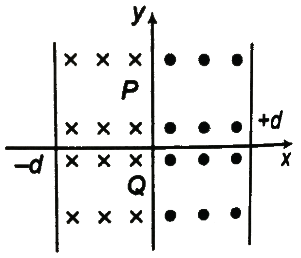
A straight conductig rod PQ is executing SHM in xy-plane from x=−d to x=+d. Its mean position is x=0 and its length is along y-axis. There exists a uniform magnetic field B from x=−d to x=0 pointing inward normal to the paper andfrom x=0 to x=+d there exists another uniform magnetic field of same magnetic B but pointing outward normal to the plane of the paper. At the instant t=0, the rod is at x=0 and moving to the right. The induced emf (epsilon) acorss the rod PQ vs time (t) graph will be
 View Solution
Question 103
Two parallel long straight conductors lie on a smooth plane surface. Two other parallel conductors rest on them at right angle so as to form a square of side a. A uniform magnetic field B exists at right angle to the plane containing the conductors. Now, conductors starts moving outward witha constant velocity v0 at t=0. Then, induced current in the loop at any time is (λ is resistance per unit length of the conductors)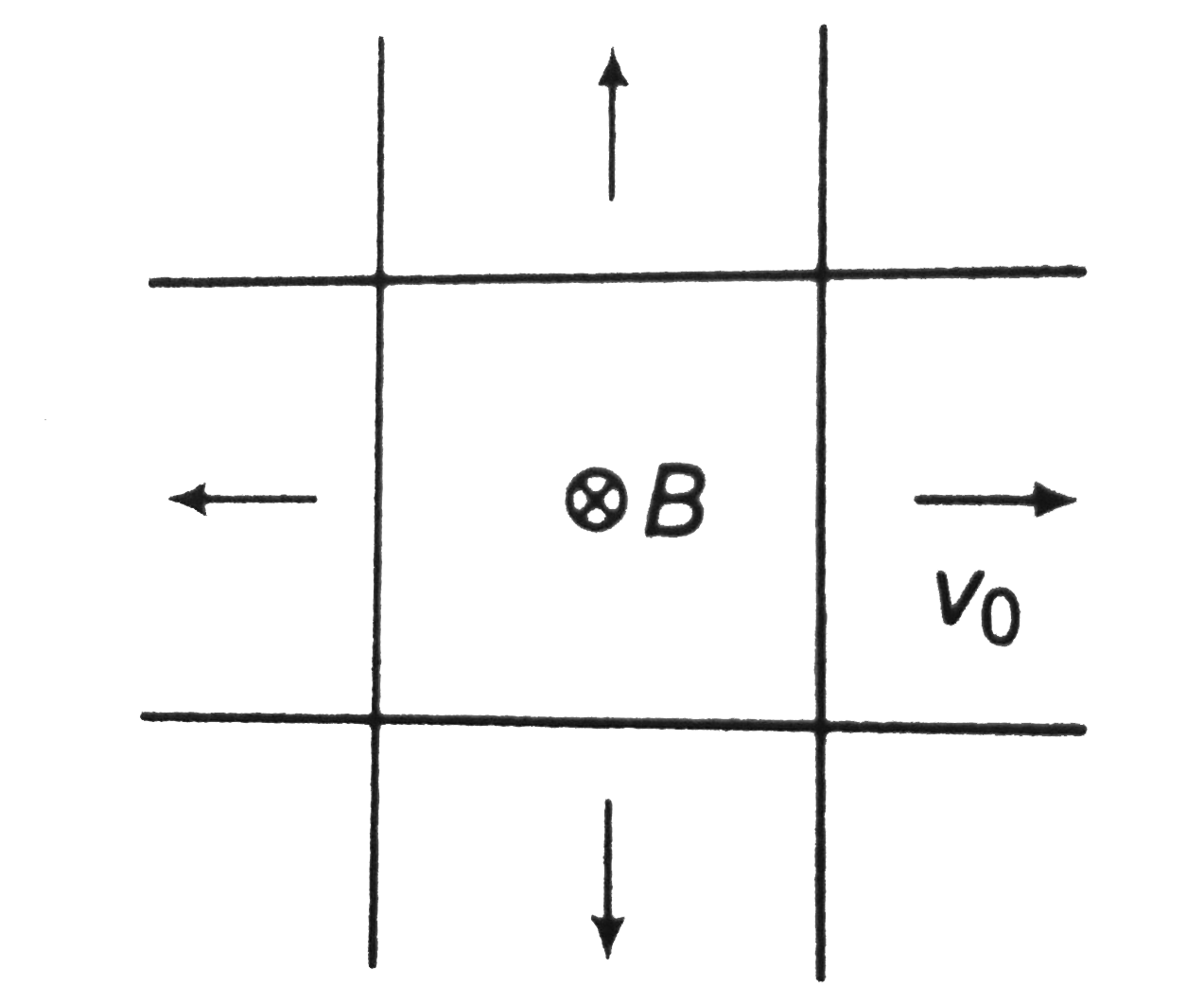 View Solution
Question 105
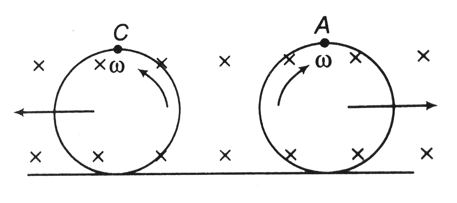
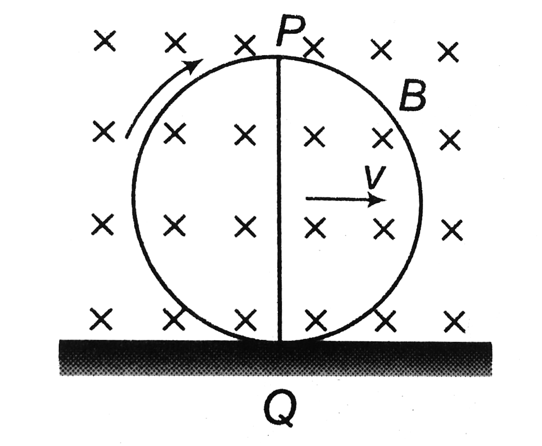
A conducting straight wire PQ of length l is fixed along as diameter of a non conducting ring as shown in the figure. The ring is given a pure rolling motion as shown. Field B is horizontal in direction and perpendicular to the plane of ring. The magnitude of induced EMF in the wire PQ at the position shown in figure will be
 View Solution
Question 107
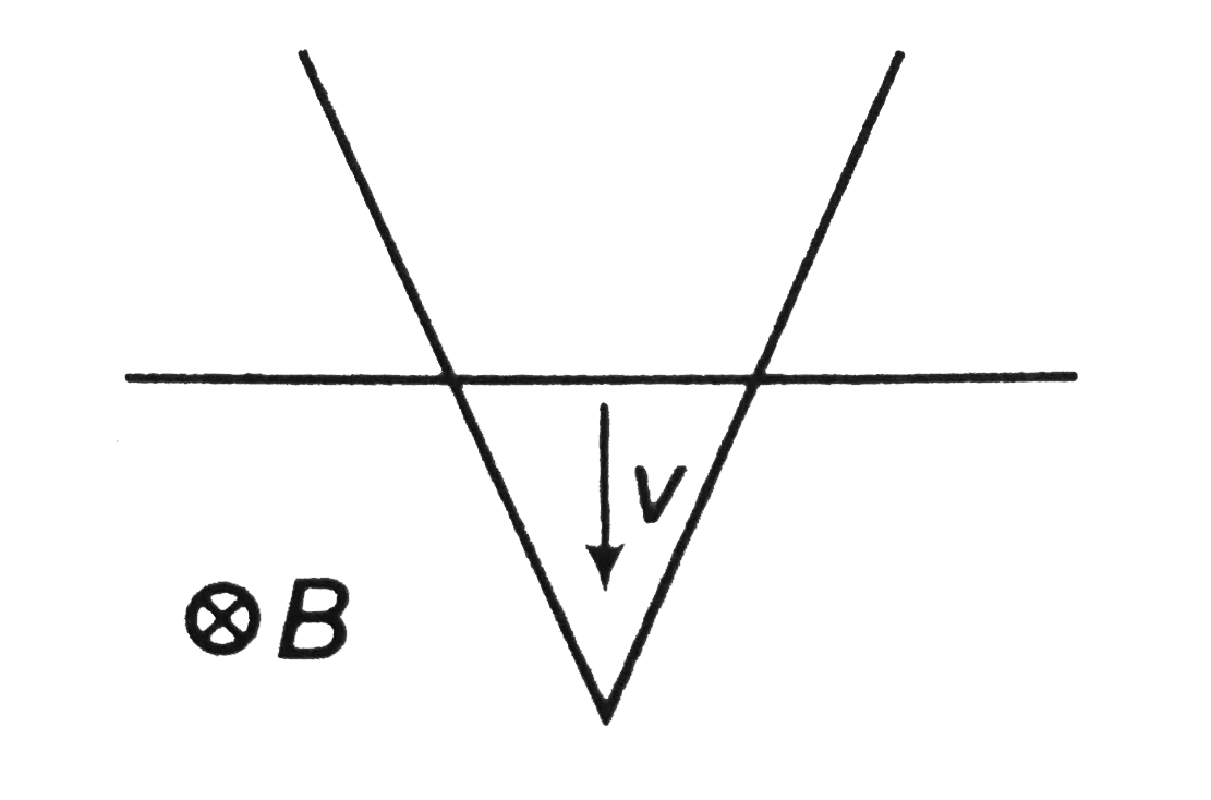
A wire is bent in the form of a V shape and placed in a horizontal plane.There exists a uniform magnetic field B perpendicular to the plane of the wire. A uniform conducting rod starts sliding over the V shaped wire with a constant speed v as shown in the figure. If the wire no resistance, the current in rod wil
 View Solution
Question 109
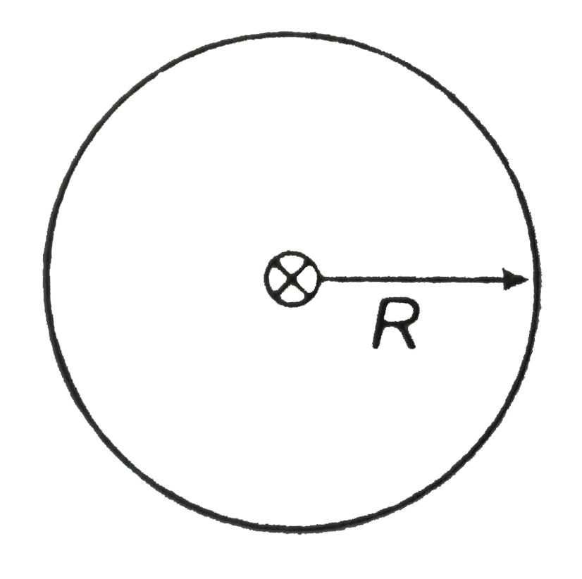
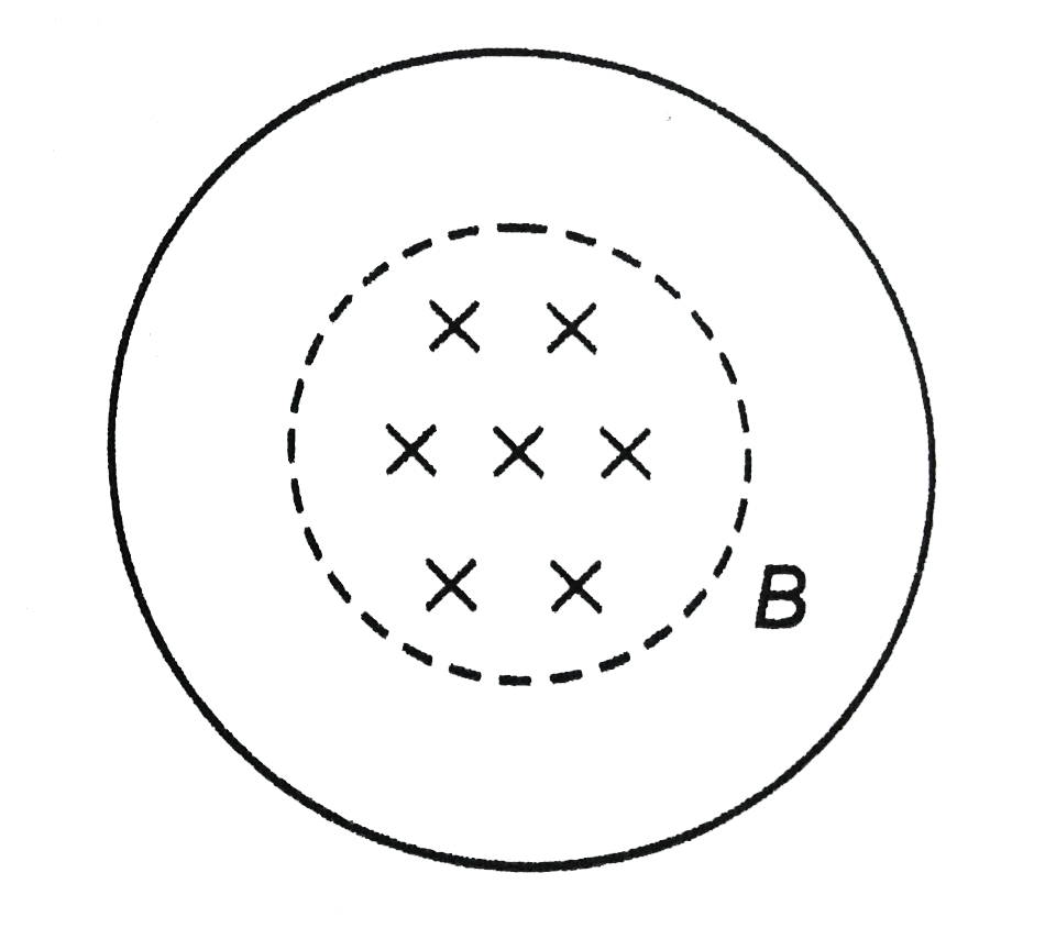
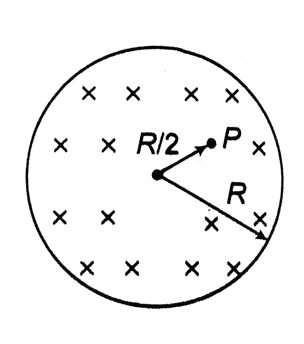
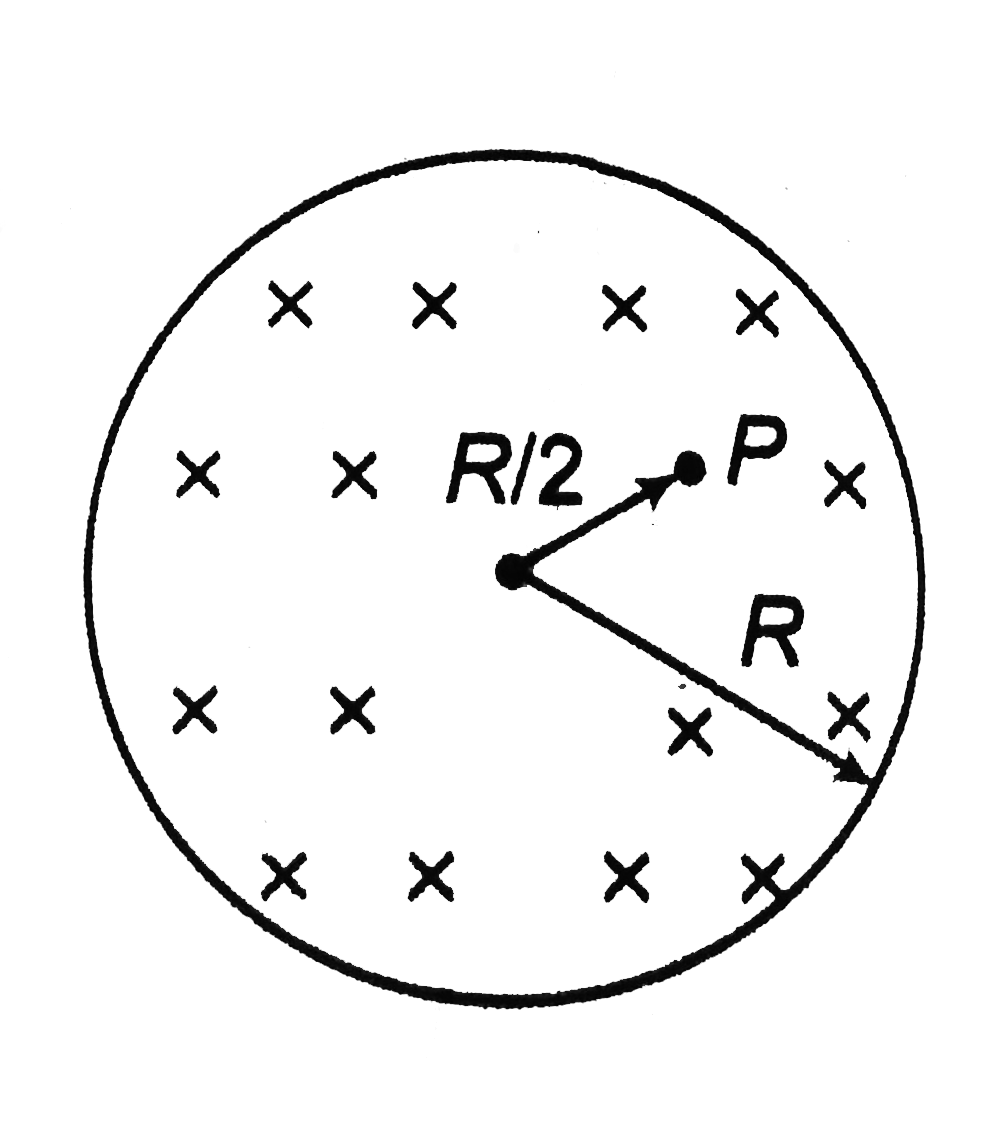
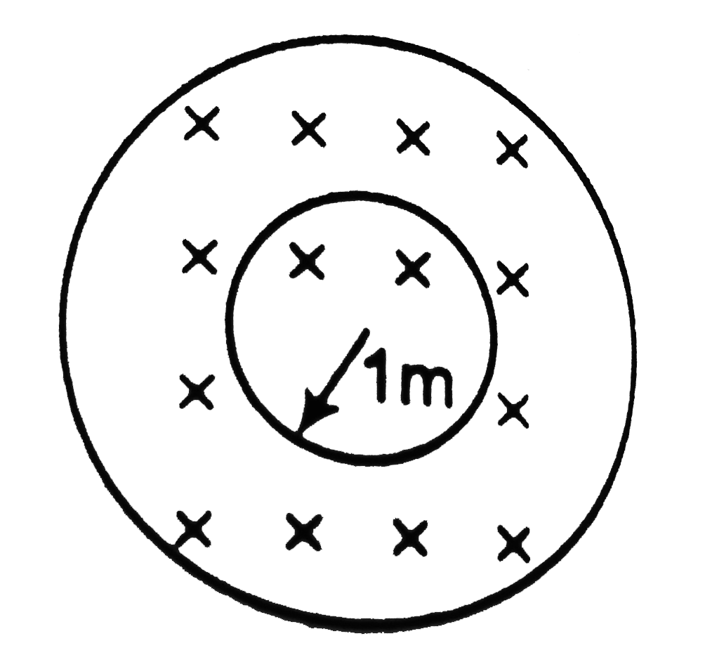
A uniform but time varying magnetic field exists in a cylindrical region as shown in the figure. The direction of magnetic field is into the plane of the paper and its magnitude is decreasing at a constant rate of 2×10⁻³T/s. A particle of charge 1μC is moved slowly along circle of radius 1m by an external force as shown in figure. The plane of the circle of radius 1m by an external force as shown in figure. The plane of he circle lies in the plane of the paper and it is concentric with the cylindrical region. The work done by the external force in moving this charge along the circle will be
 View Solution
Question 120
A conducnting straight wire PQ of length l is fixed along as diameter of a non conducting ring as shown in the figure. The ring is given a pure rolling motion on as horizontal masgnetic field B in horizontal direction perpendicular to the plane of ring. The magnitude of induced emf in the wire PQ at the position shown in figure will be
 View Solution
Question 149
A thin non conducting ring of mass m, radius a carrying a charge q can rotate freely about its own axis which is vertical. At the initial moment, the ring was at rest in horizontal position and no magnetic field was present. At instant t=0, a uniform magnetic field is switched on which is vertically downward and increases with time according to the law B=B0t. Neglecting magnetism induced due to rotational motion of ring.
The magnitude of induced emf of the closed surface of ring will beView SolutionQuestion 150
A thin non conducting ring of mass m, radius a carrying a charge q can rotate freely about its own axis which is vertical. At the initial moment, the ring was at rest in horizontal position and no magnetic field was present. At instant t=0, a uniform magnetic field is switched on which is vertically downward and increases with time according to the law B=B0t. Neglecting magnetism induced due to rotational motion of ring.
The magnitude of an electric field on the circumference of the ring is View SolutionQuestion 151
A thin non conducting ring of mass m, radius a carrying a charge q can rotate freely about its own axis which is vertical. At the initial moment, the ring was at rest in horizontal position and no magnetic field was present. At instant t=0, a uniform magnetic field is switched on which is vertically downward and increases with time according to the law B=B0t. Neglecting magnetism induced due to rotational motion of ring.
Angular acceleration of ring is View SolutionQuestion 152
A thin non conducting ring of mass m, radius a carrying a charge q can rotate freely about its own axis which is vertical. At the initial moment, the ring was at rest in horizontal position and no magnetic field was present. At instant t=0, a uniform magnetic field is switched on which is vertically downward and increases with time according to the law B=B0t. Neglecting magnetism induced due to rotational motion of ring.
Find intantaneous power developed by electric force acting on the ring at t=1s View SolutionQuestion 153
Figure shows a conducting rod of negligible resistance that can slide on smooth U-shaped rail made of wire of resistance 1Ω/m. Position of the conducting rod at t=0 is shown. A time dependent magnetic field B=2t tesla is switched on at t=0
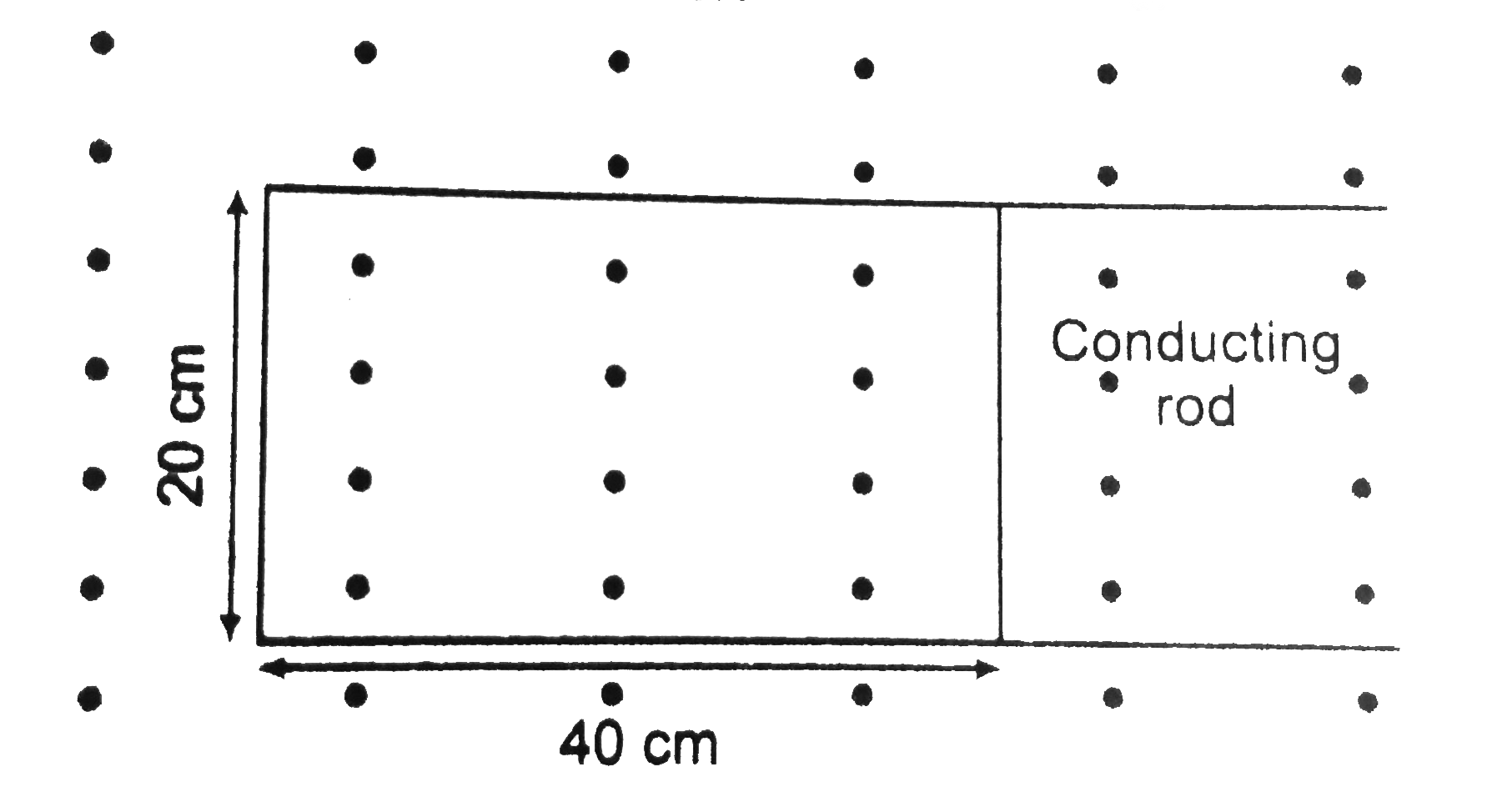
The current in the loop at t=0 due to induced emf isView SolutionQuestion 154
Figure shows a conducting rod of negligible resistance that can slide on smooth U-shaped rail made of wire of resistance 1Ω/m. Position of the conducting rod at t=0 is shown. A time dependent magnetic field B=2t tesla is switched on at t=0
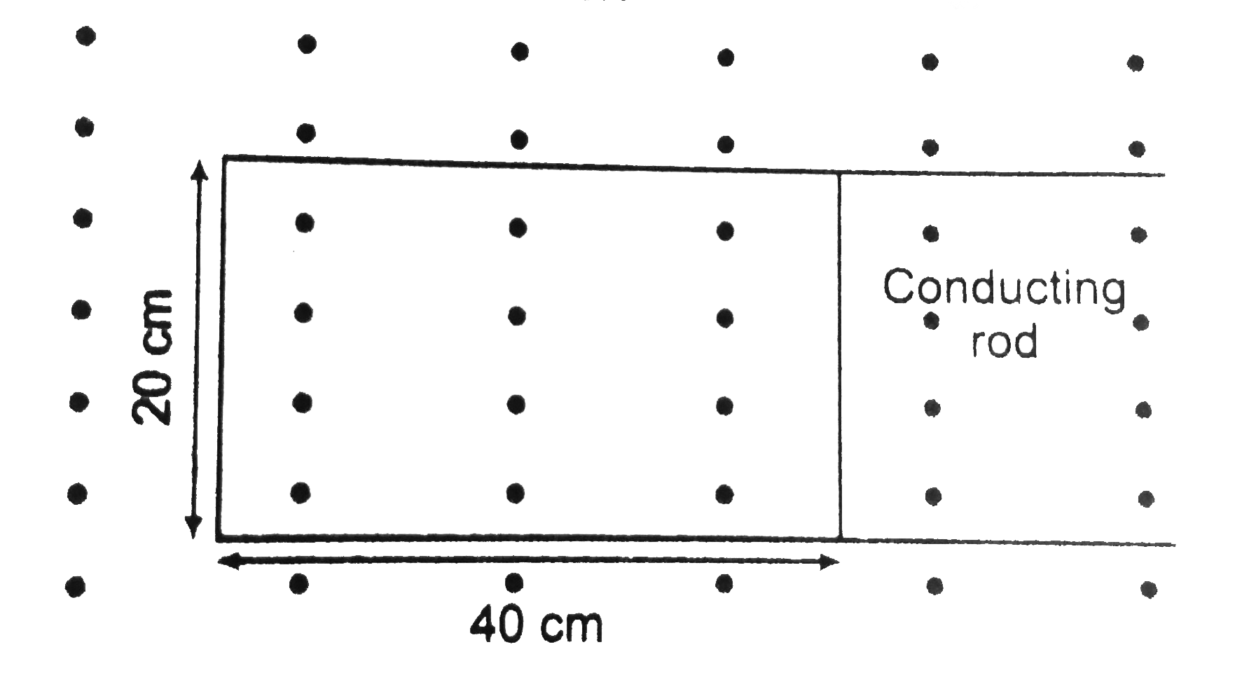
At t=0, when the magnetic field is switched on, the conducting rod is moved to the left at constant speed 5cm/s by some external means. At t=2s, net induced emf has magnitudeView SolutionQuestion 155
Figure shows a conducting rod of negligible resistance that can slide on smooth U-shaped rail made of wire of resistance 1Ω/m. Position of the conducting rod at t=0 is shown. A time dependent magnetic field B=2t tesla is switched on at t=0
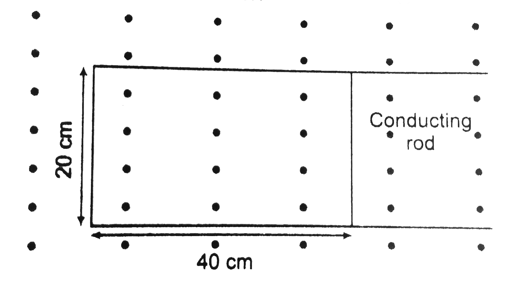 The magnitude of the force required to move the conducting rod at constant speed 5cm/s at the same instant t=2s, is equal toView Solution
Question 156
Two parallel vertical metallic rails AB and CD are separated by 1m. They are connected at the two ends by resistances R1 and R2 as shown in the figure. A horizontal metallic bar l of mass 0.2kg slides without friction, vertically down the rails under the action of gravity. There is a uniform horizontal magnetic field of 0.6T perpendicular to the plane of the rails. It is observed that when the terminal velocity is attained, the powers dissipated in R1 and R2 are 0.76W and 1.2W respectively (g=9.8m/s2)
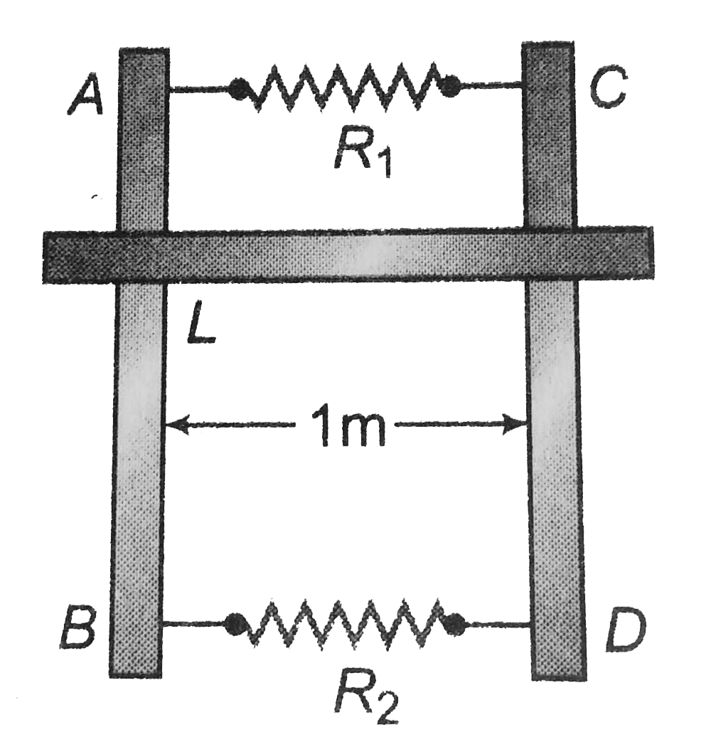
The terminal velocity fo the bar L will be View SolutionQuestion 157
Two parallel vertical metallic rails AB and CD are separated by 1m. They are connected at the two ends by resistances R1 and R2 as shown in the figure. A horizontal metallic bar l of mass 0.2kg slides without friction, vertically down the rails under the action of gravity. There is a uniform horizontal magnetic field of 0.6T perpendicular to the plane of the rails. It is observed that when the terminal velocity is attained, the powers dissipated in R1 and R2 are 0.76W and 1.2W respectively (g=9.8m/s2)
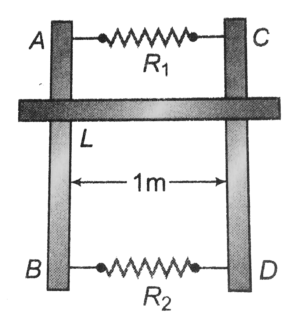
The value of R1 is View SolutionQuestion 158
Two parallel vertical metallic rails AB and CD are separated by 1m. They are connected at the two ends by resistances R1 and R2 as shown in the figure. A horizontal metallic bar l of mass 0.2kg slides without friction, vertically down the rails under the action of gravity. There is a uniform horizontal magnetic field of 0.6T perpendicular to the plane of the rails. It is observed that when the terminal velocity is attained, the powers dissipated in R1 and R2 are 0.76W and 1.2W respectively (g=9.8m/s2)
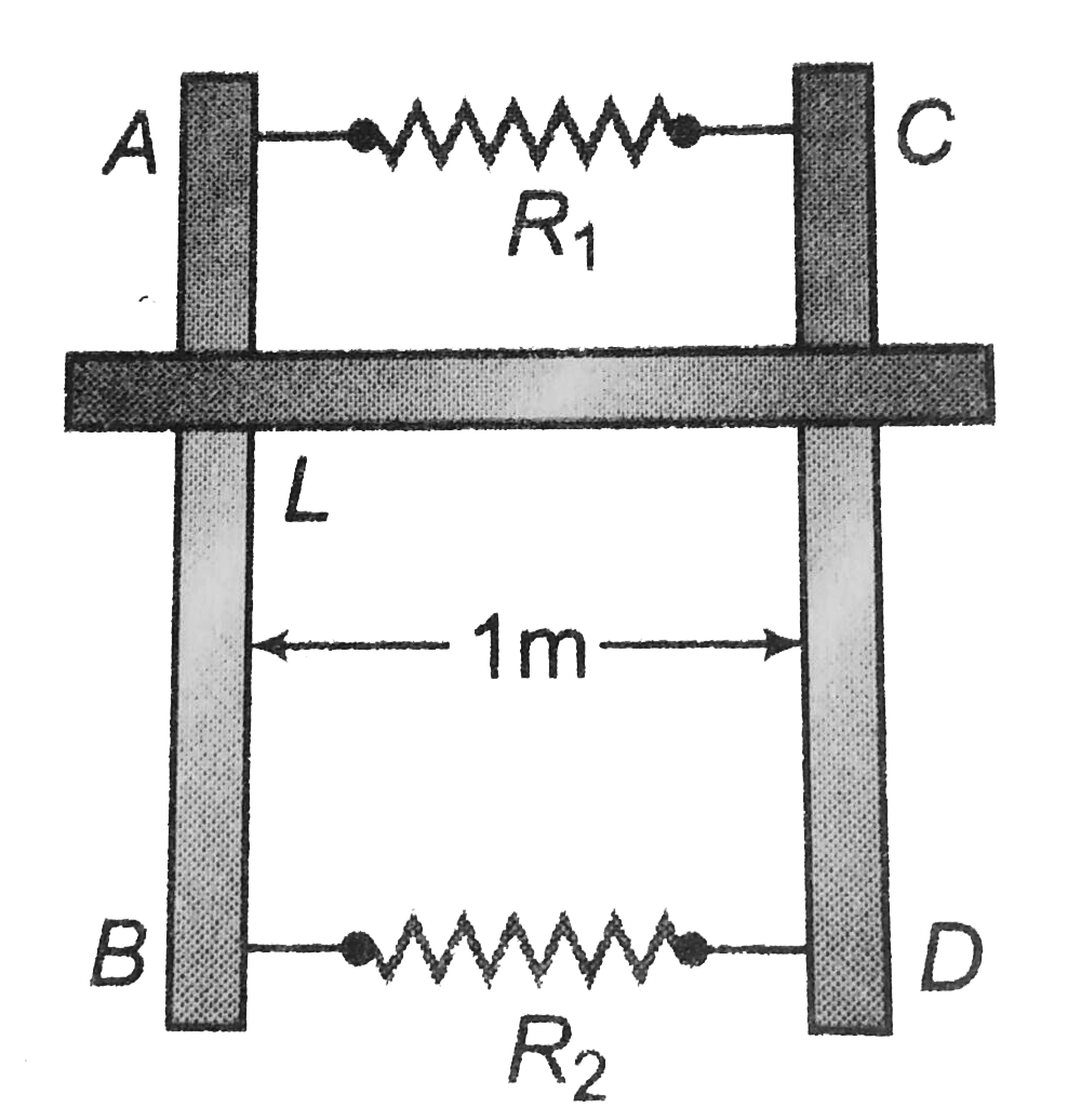
The value of R2is View SolutionQuestion 160
A rectangular loop with a sliding connector of length l is located in a uniform magnetic field perpendicular to the loop plane. The magnetic induction is equal to B. The connector has an electric resistance R, the sides ab and cd have resistances R1 and R2. Neglecting the self-inductance of the loop, find the current flowing in the connector during its motion with a constant velocity v.
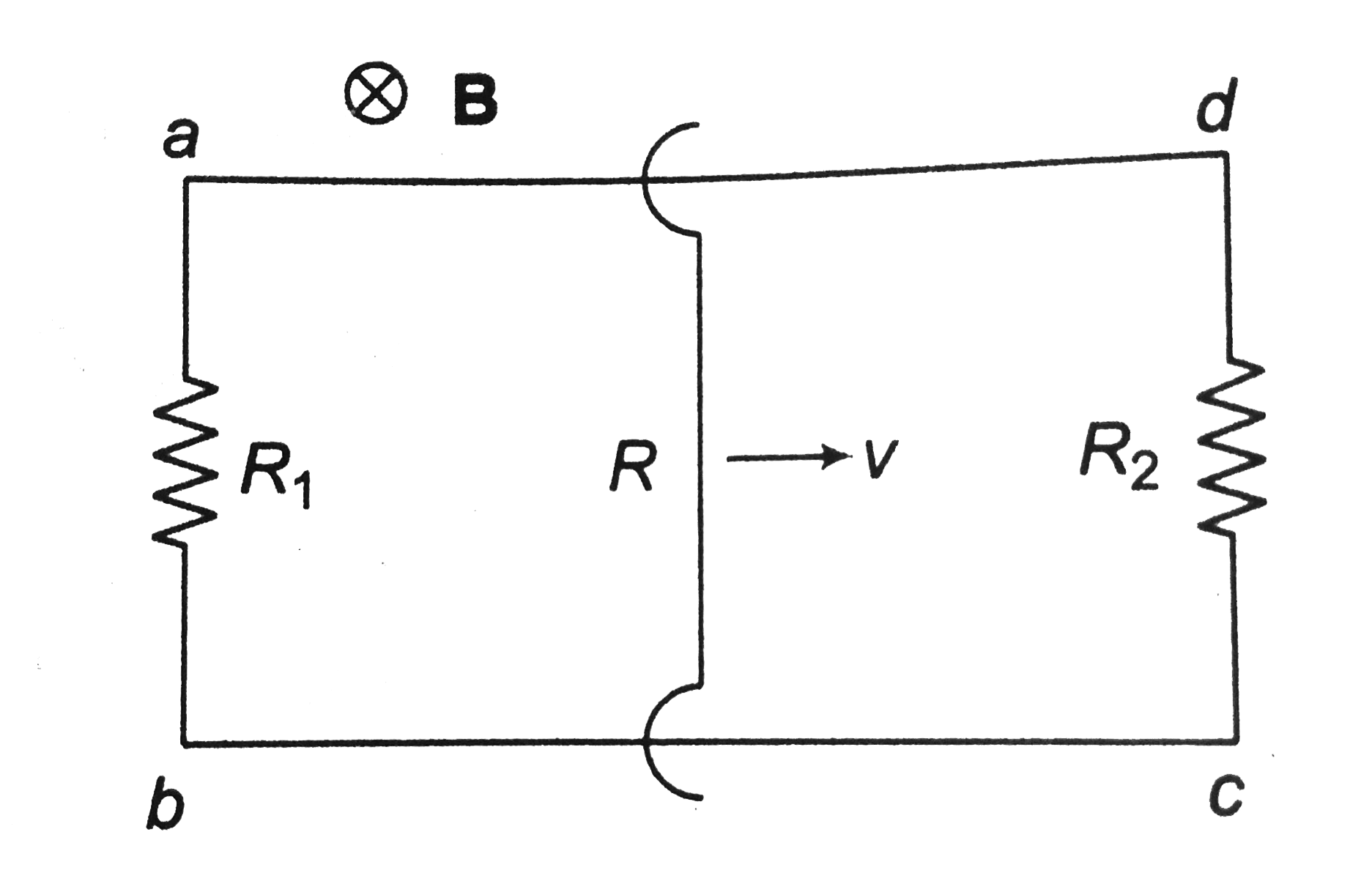 View Solution
Question 161
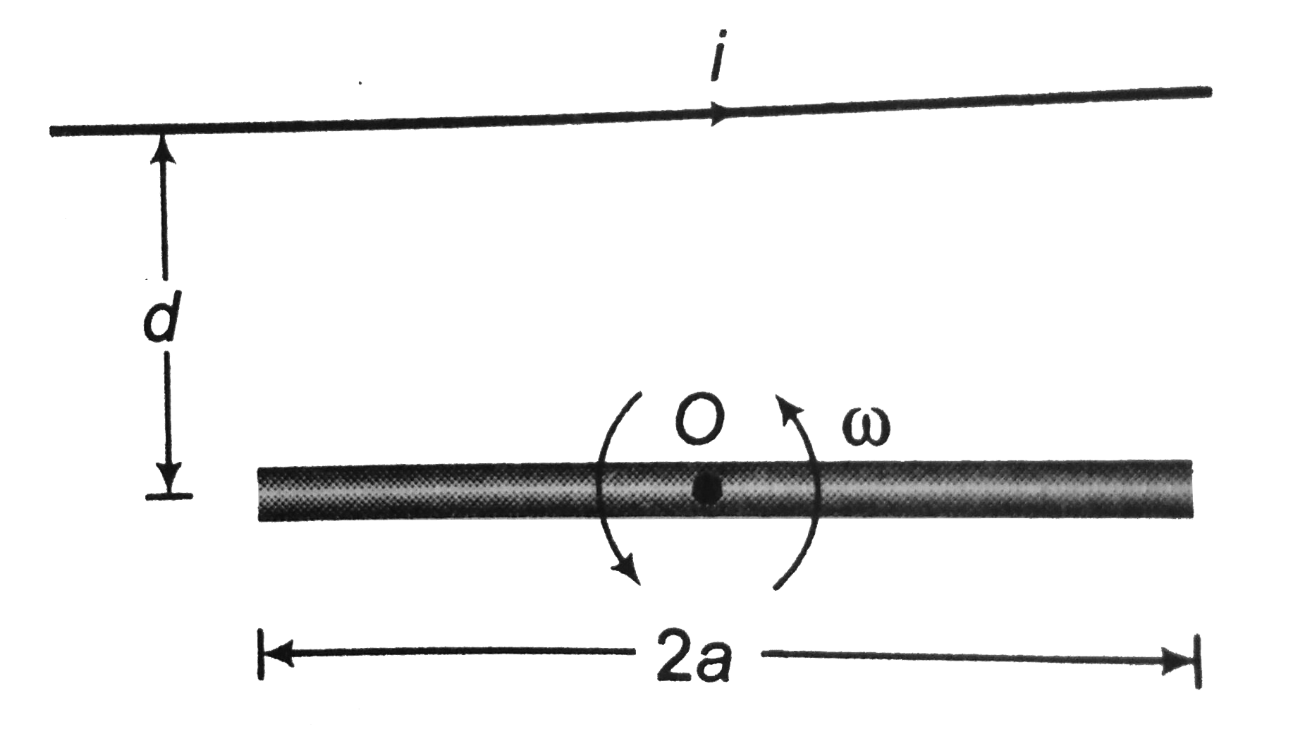
A rod of length 2a is free to rotate in a vertical plane, about a horizontal axis O passing through its mid-point. A long straight, horizontal wire is in the same plane and is carrying a constant current i as shown in figure. At initial moment of time, the rod is horizontal and starts to rotate with constant angular velocity ω, calculate emf induced in the rod as a function of time.
 View Solution
Question 164
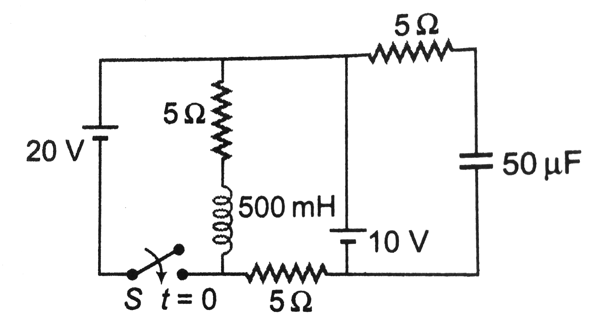
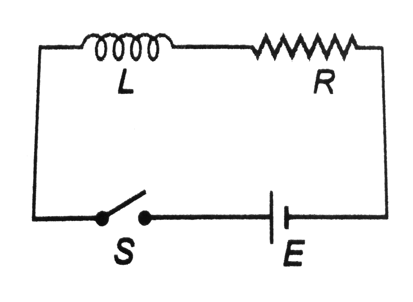
In the circuit shown in figure, E=120V,R1=30.0Ω,R2=50.0Ω and L=0.200H. Switch S is closed at t=0. Just after the switch is closed.
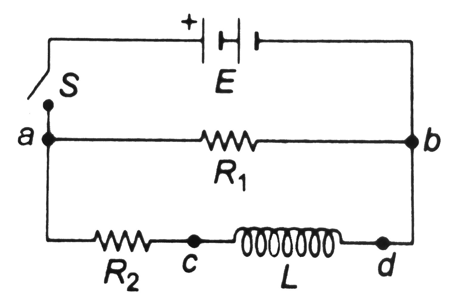
(a) What is the potential difference Vab across the inductor R1?
(b) Which point, a or b, is at higher potential?
(c) What is the potential difference Vcd across the inductor L?
(d) Which point, c or d, is at a higher potential? The switch is left closed for a long time and then is opened. Just after the switch is opened
(e) What is the potential difference Vab across the resistor R1?
(f) Which point a or b, is at a higher potential?
(g) What is the potential difference Vcd across the inductor L?
(h) Which point, c or d, is at a higher potential? View SolutionQuestion 165
Two capacitors of capacitances 2C and C are connected in series with an inductor of inductance L. Initially, capacitors have charge such that VB−VA=4V0 and VC−VD=V0. Initial current in the circuit is zero. Find
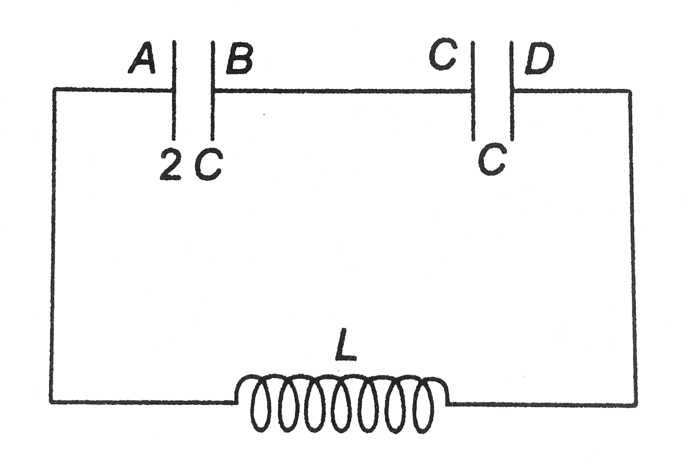
(a) maximum current that will flow in the circuit,
(b) potential difference across each capacitor at that instant,
(c) equation of current flowing towards left in the inductor. View SolutionQuestion 166
A 1.00mH inductor and a 1.00μF capacitor are connected in series. The current in the circuit is described by i=20t, where t, is in second and i is in ampere. The capacitor initially has no charge. Determine
(a) the voltage across the inductor as a function of time,
(b) the voltage across the capacitor as a function of time,
(c) the time when the energy stored in the capacitor first exceeds that in the inductor.View SolutionQuestion 167
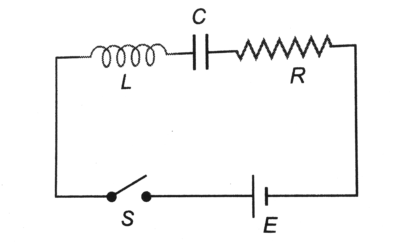
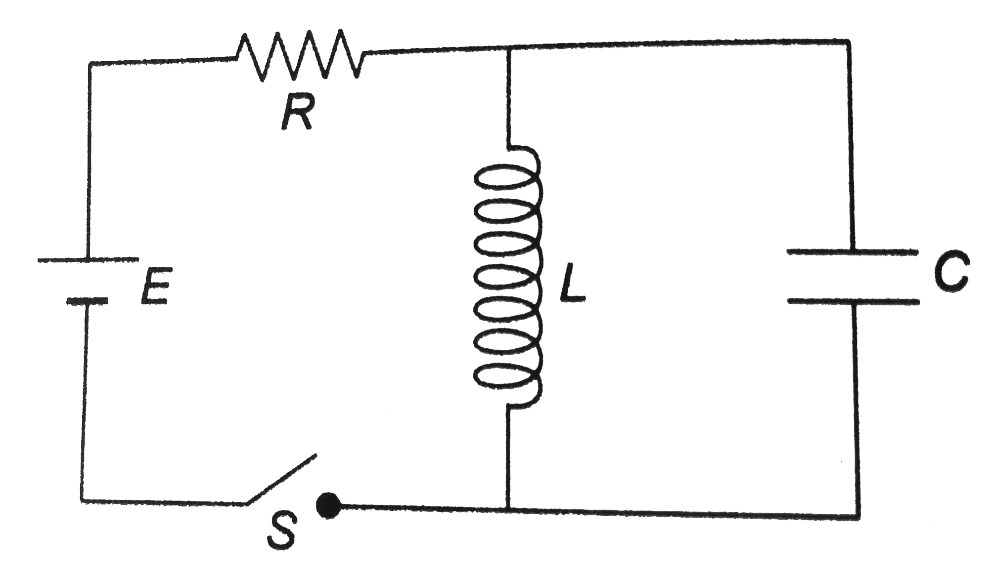
In the circuit shown in the figure, E=50.0V,R=250Ω and C=0.500μF. The switch S is closed for a long time, and no voltage is measured across the capacitor. After the switch is opened, the voltage across the capacitor reaches a maximum value of 150V. What is the inductance L?
 View Solution
Question 168
The conducting rod ab shown in figure makes contact with metal rails ca and db. The apparatus is in a uniform magnetic field 0.800T, perpendicular to the plane of the figure.
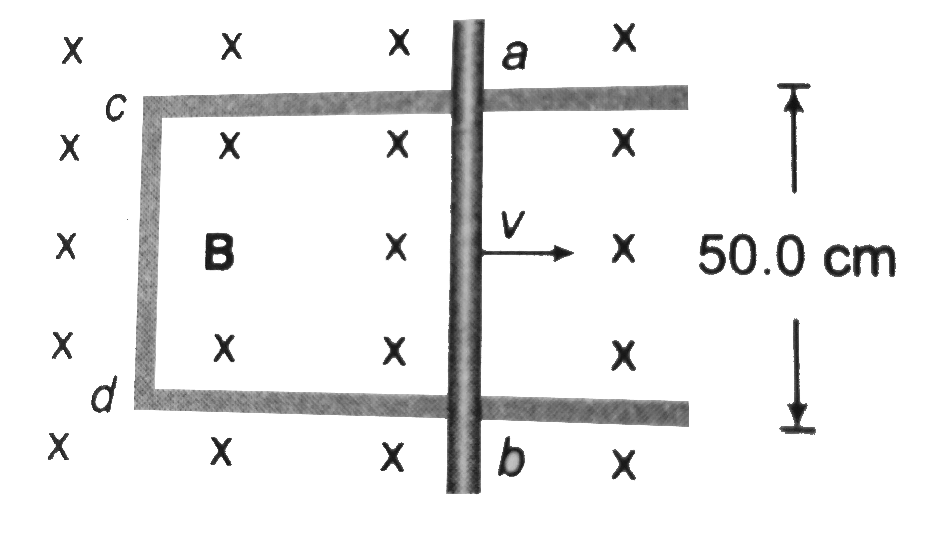
(a) Find the magnitude of the emf induced in the rod when it is moving toward the right with a speed 7.50m/s.
(b) In what direction does the current flow in the rod?
(c) If the resistance of the circuit abdc is 1.50Ω (assumed to be constant), find the force (magnitude and direction) required to keep the rod moving to the right with a constant speed of 7.50m/s. You can ignore friction.
(d) Compare the rate at which mechanical work is done by the force (Fu) with the rate at which thermal energy is developed in the circuit (I2R). View SolutionQuestion 169
A non-conducting ring of mass m and radius R has a charge Q uniformly distributed over its circumference. The ring is placed on a rough horizontal surface such that plane of the ring is parallel to the surface. A vertical magnetic field B=B0t2 tesla is switched on. After 2 a from switching on the magnetic field the ring is just about to rotate about vertical axis through its centre.
(a) Find friction coefficient μ between the ring and the surface.
(b) If magnetic field is switched off after 4s, then find the angle rotated by the ring before coming to stop after switching off the magnetic field. View SolutionQuestion 170
Two parallel long smooth conducting rails separated by a distance l are connected by a movable conducting connector of mass m. Terminals of the rails are connected by the resistor R and the capacitor C as shown in figure. A uniform magnetic field B perpendicular to the plane of the rail is switched on. The connector is dragged by a constant force F. Find the speed of the connector as a function of time if the force F is applied at t=0. Also find the terminal velocity of the connector.
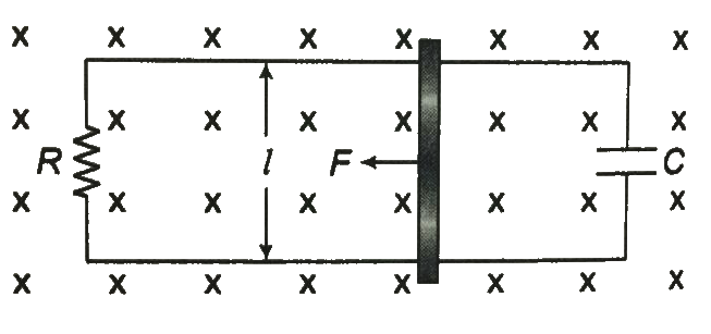 View Solution
Question 171
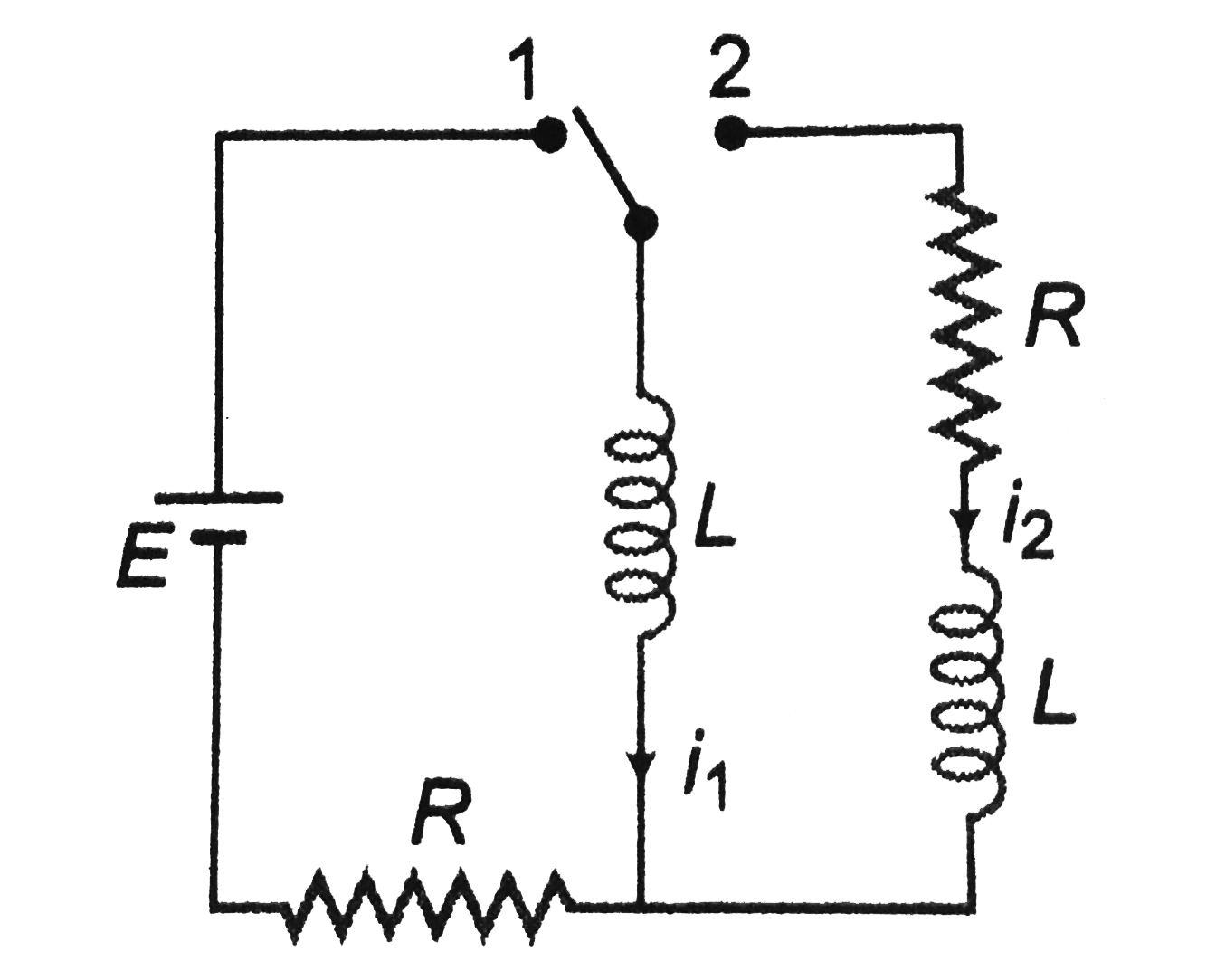
A circuit containing capacitors C1 and C2, shown in the figure is in the steady state with key K1 and K2 opened. At the instant t=0, K1 is opened and K2 is closed.
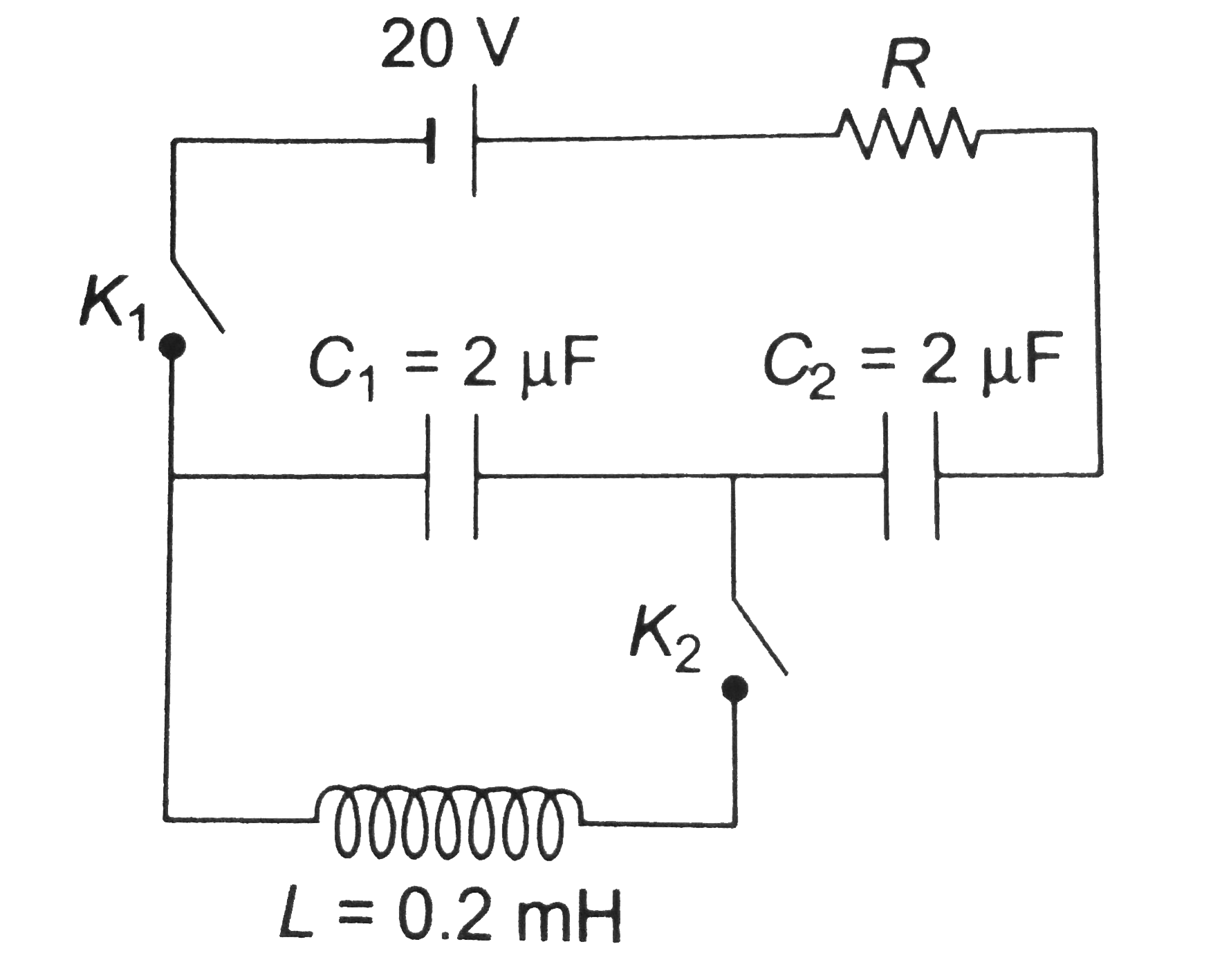
(a) Find the angular frequency of oscillations of L−C circuit.
(b) Determine the first instant t, when energy in the inductor becomes one third of that in the capacitor.
(c) Calculate the charge on the plates of the capacitor at that instant.View SolutionQuestion 172
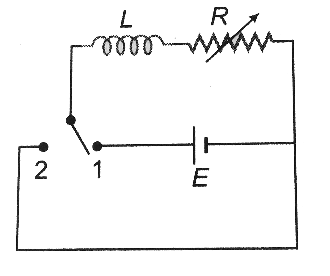
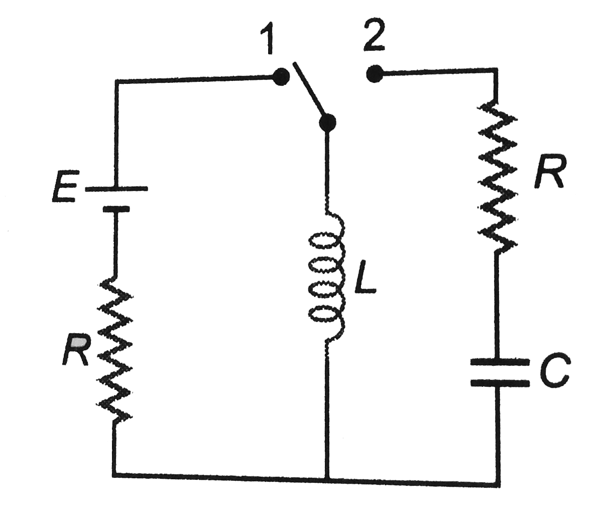
Initially, the capacitor is charged to a potential of 5V and then connected to position 1 with the shown polarity for 1s. After 1s it is connected across the inductor at position 2
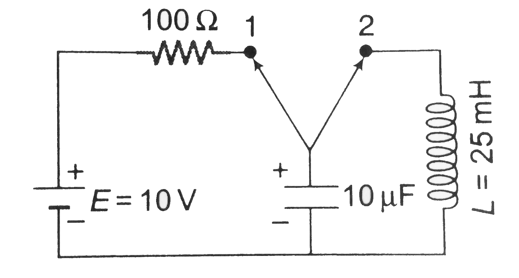
(a) Find the potential across the capacitor after 1s of its connection to position 1.
(b) Find the maximum current flowing in the L−C circuit when capacitor is connected across the inductor. Also, find the frequency of LC oscillations. View SolutionQuestion 174
Two metal bars are fixed vertically and are connected on the top by a capacitor C. A sliding conductor of length land mass m slides with its ends in contact with the bars. The arrangement is placed in a uniform horizontal magnetic field directed normal to the plane of the figure. The conductor is released from rest. Find the displacement x(t) of the conductor as a function of time t.
 View Solution
Question 175
A conducting light string is wound on the rim of a metal ring of radius r and mass m. The free end of the string is fixed to the ceiling. A vertical infinite smooth conducting plane is always tangent to the ring as shown in the figure. A uniform magnetic field Bis applied perpendicular to the plane of the ring. The ring is always inside the magnetic field. The plane and the strip are connected by a resistance R. When the ring is released, find
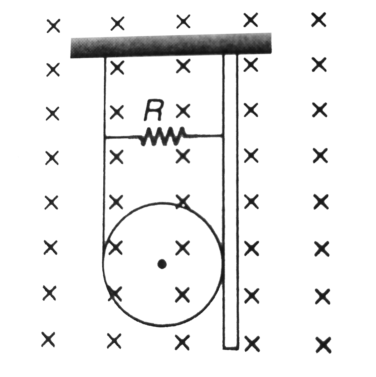
a. the curent in the resistance R as as function of time.
b. the terminal velocity of the ring.View SolutionQuestion 176
A conducting frame abcd is kept in a vertical plane. A conducting rod of of mass m and length l can slide smoothly on it remaining always horizontal. The resistance of the loop is negligible and inductance is constant having value L. The rod is left from rest and allowed to fall under gravity and inductor has no initial current. A magnetic field of constant magnitude Bis present throughout the loop pointing inwards. Determine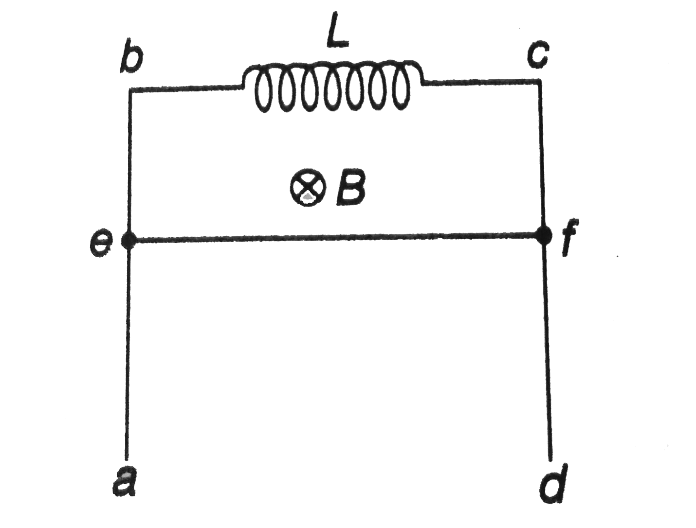
(a) position of the rod as a function of time assuming initial position of the rod to be x=0 and vertically downward as the positive x-axis.
(b) the maximum current in the circuit.
(c) maximum velocity of the rod View SolutionQuestion 177
A rectangular loop with a sliding conductor of length l is located in a uniform magnetic field perpendicular to the plane of loop. The magnetic induction perpendicular to the plane of loop Is equal to B. The part ad and be has electric resistance R1 and R2, respectively. The conductor starts moving with constant acceleration a0, at time t=0. Neglecting the self-inductance of the loop and resistance of conductor. Find
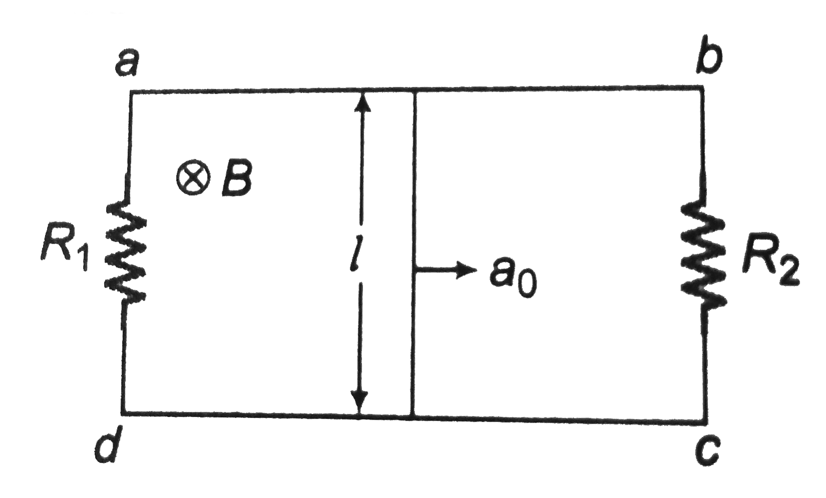
(a) the current through the conductor during its motion.
(b) the polarity of abcd terminal.
(c) external force required to move the conductor with the given acceleration.View SolutionQuestion 178
A conducting circular loop of radius a and resistance per unit length R is moving with a constant velocity v0 , parallel to an infinite conducting wire carrying current i0. A conducting rod of length 2a is approaching the centre of the loop with a constant velocity v02 along the direction 2 of the current. At the instant t=0, the rod comes in contact with the loop at A and starts sliding on the loop with the constant velocity. Neglecting the resistance of the rod and the self-inductance of the circuit, find the following when the rod slides on the loop.
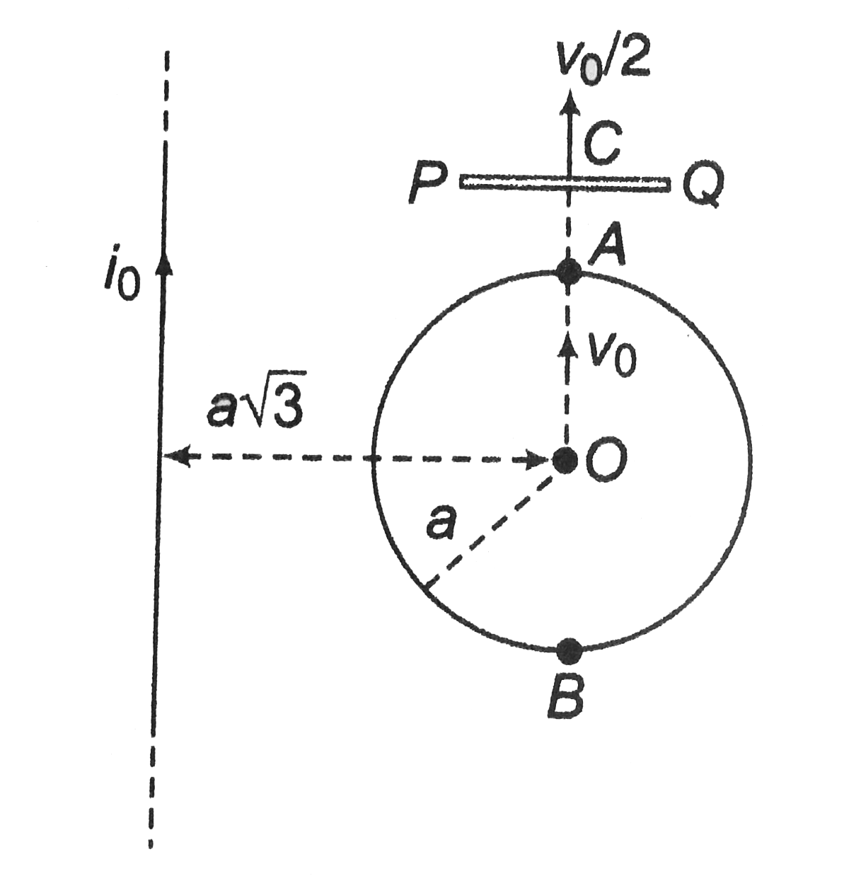
(a) The current through the rod when it is at a distance of (a2) from the point A of the loop.
(b) Force required to maintain the velocity of the rod at that instant. View SolutionQuestion 179
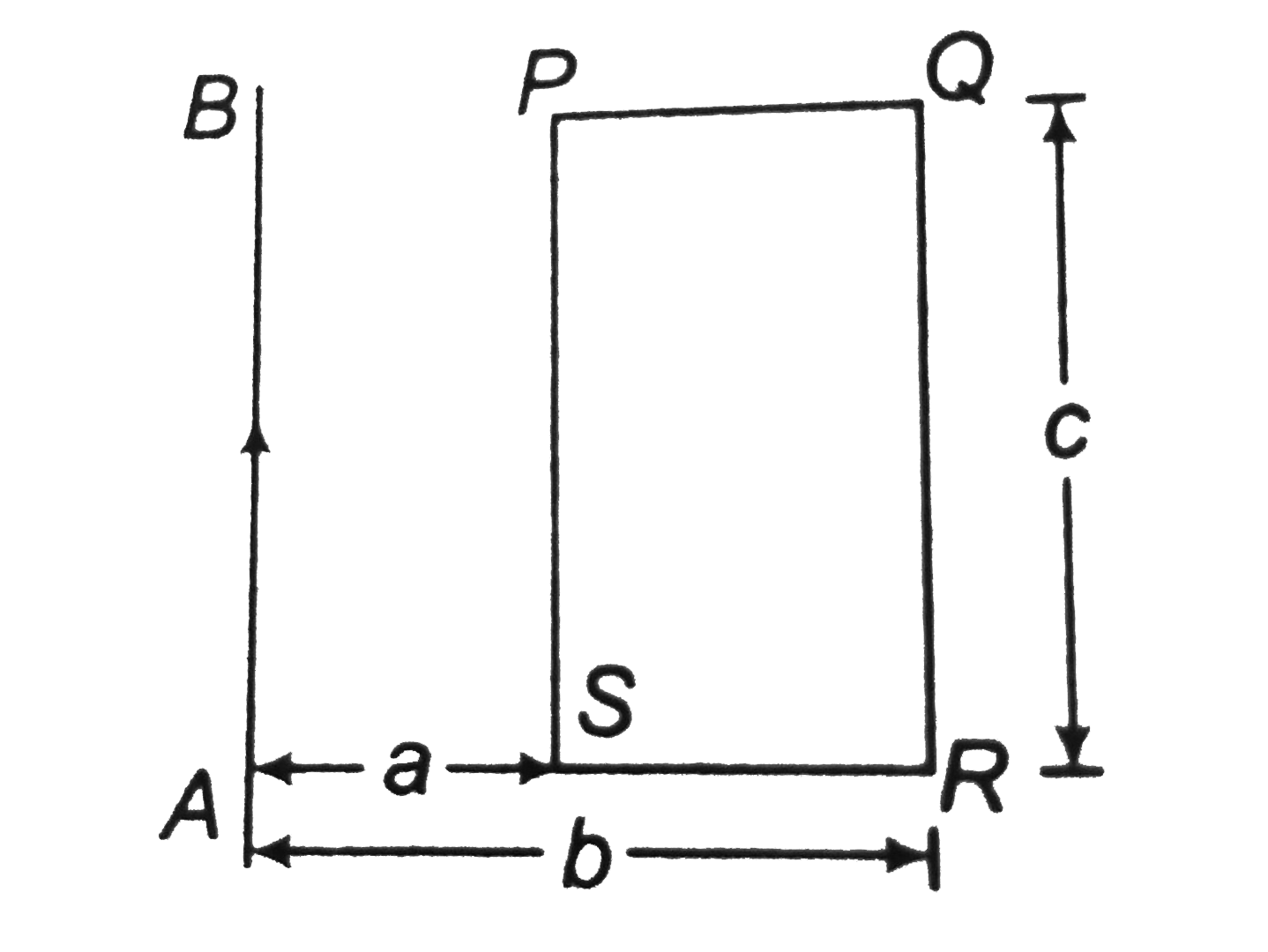
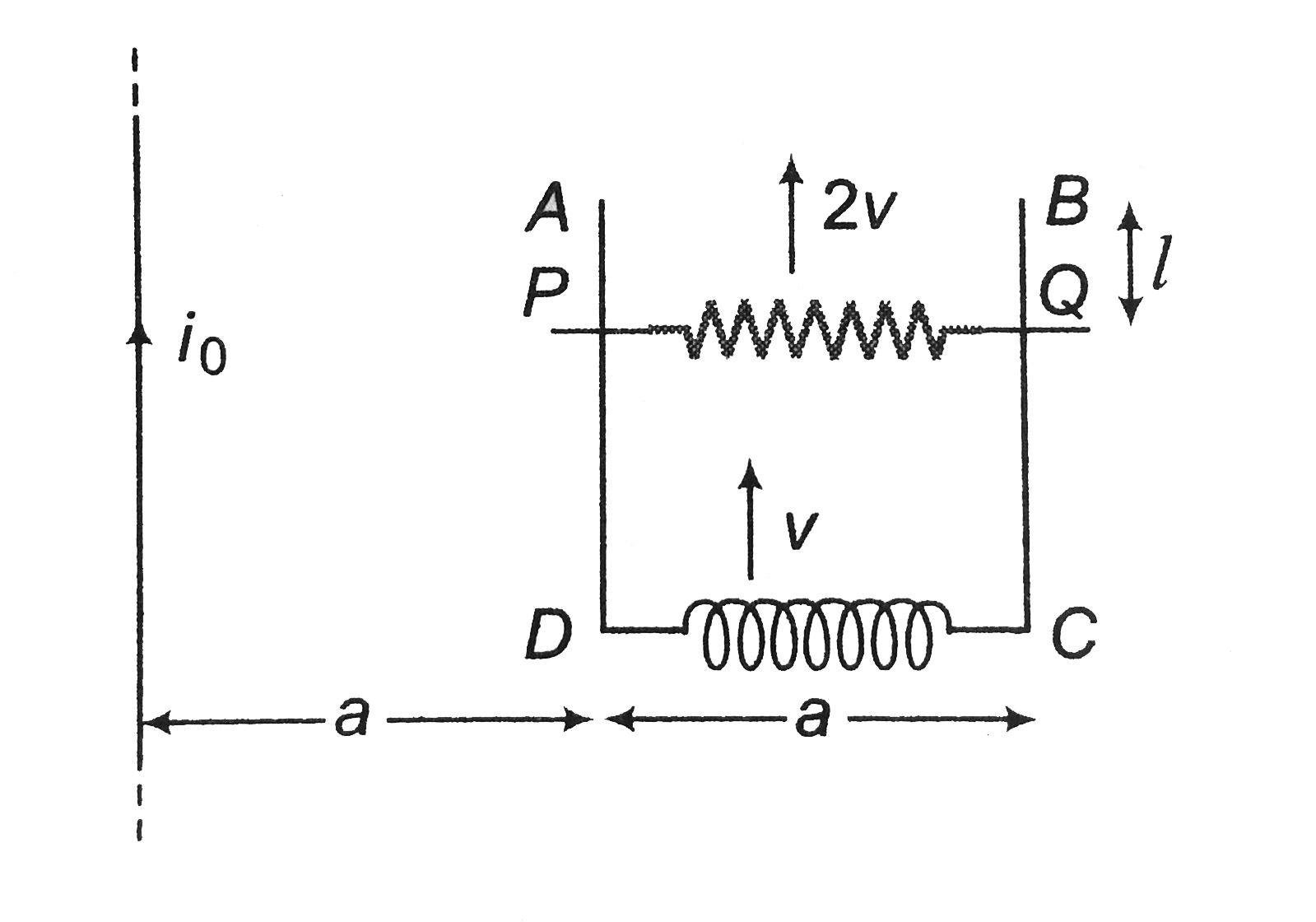
U-frame ABCD and a sliding rod PQ of resistance R, start moving with velocities v and 2v respectively, parallel to a long wire carrying current i0. When the distance AP=1 at t=0, determine the current through the inductor of inductance L just before connecting rod PQ loses contact with the U-frame.
 View Solution
All Exercises from DC PANDEY ENGLISH Class 12 PHYSICS ELECTROMAGNETIC INDUCTION
- CHECK POINT
- EXERCISE 27.1
- EXERCISE 27.2
- EXERCISE 27.3
- EXERCISE 27.4
- EXERCISE 27.5
- EXERCISE 27.6
- EXERCISE 27.7
- LEVEL 1 ASSERTION AND REASON
- LEVEL 1 OBJECTIVE
- LEVEL 1 SUBJECTIVE
- LEVEL 2 COMPREHENSION BASED
- LEVEL 2 MORE THAN ONE CORRECT
- LEVEL 2 SINGLE CORRECT
- LEVEL 2 SUBJECTIVE
- MATCH THE COLUMNS
- MEDICAL ENTRANCE SPECIAL FORMAT QUESTIONS
- MEDICAL ENTRANCES GALLERY
- OBJECTIVE QUESTIONS
- SUBJECTIVE TYPE
- TAKING IT TOGETHER
- EXAMPLE
- EXAMPLE TYPE 1
- EXAMPLE TYPE 2
- EXAMPLE TYPE 3
- EXAMPLE TYPE 4
- EXAMPLE TYPE 5
- EXAMPLE TYPE 6
- MISCELLANEOUS EXAMPLES
