Complete Solutions to problem of chapter AC CIRCUITS AND ELECTRIC CIRCUITS of Class 12 book with complete answers and questions
| Class 12 | PHYSICS |
| Chapter | AC CIRCUITS AND ELECTRIC CIRCUITS |
| SL ARORA | problem |
| Number Of Questions | 57 |
| Academic Year | 2023-24 |
An a.c. source of angular frequency `omega` is fed across a resistor R and a capacitor C in series. The current registered is I. If now the frequency of the source is changed to `omega//3` (but maintaining the same voltage), the current in the circuit is found to be halved. calculate the ratio of reactance to resistance at the original frequency `omega`.
03:45View SolutionAn `L-C-R` series circuit with `100Omega` resistance is connected to an `AC` source of `200V` and angular frequency `300rad//s`. When only the capacitance is removed, the current lags behind the voltage by `60^@`. When only the inductance is removed the current leads the voltage by `60^@`. Calculate the current and the power dissipated in the `L-C-R` circuit
04:56View SolutionA current of 4 A flows in a coil when connected to a 12 V dc source. If the same coil is connected to a `12 V, 50 rad s^(-1)` ac source, a current of 2.4 A flows of the coil in the circuit.
The power developed in the circuit of a `2500 (mu)F` capacitor that is connected in series with the coil is06:13View SolutionAn `LCR` circuit has `L = 10 mH`. `R = 3` ohm and `C = 1 mu F` connected in series to a source is `15 cos omega t` volt. What is average power dissipated per cycle at a frequency that is `10%` lower than the resonant requency?
05:57View SolutionInductance (L), capacitance (C) and resistance (R) are constained in a box. When 250 V DC is applied to the terminals of the box, a current of 1.0A floes in the circuit. When an AC source of `250V_(rms)` at `2250 rad sec^(-1)` is connected, a current of `1.25 A_(rms)` flows. It is observed that the current rises with frequency and becomes maximum at `4500 rad sec^(-1)`. find the values of L,C and R. draw the circuit diagram.
13:55View SolutionA series LCR- circuit containing a resistance of `120 Omega` has angular resonance frequency `4 xx10^(5) rads^(-1)`. At resonance the voltages across resistance and inductance are 60 V and 40 V respectively. Find the values of L and C. At what frequency the current in the circuit lags the voltage by `45^(@)`?
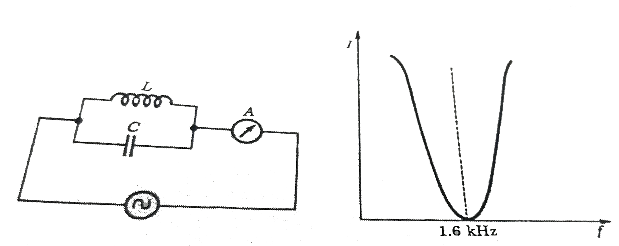
07:30View SolutionAn LC- circuit (inductance 0.01 H and capacitance `1 muF`) is connected to a variable a.c. source as shown in fig. 14.8. Draw rough sketch of the current -variation as the frequency is changed from 1 kHz to 2 kHz.
 02:51View Solution
An a.c. source is connected to two circuit as shown in fig. 14.10. Obtain the current through the resistance R at resonance in both the circuits.
 03:08View Solution
The current in a coil of self-inductance 2.0 H is increasing according to `I=2 sin t^(2)` ampere. Find the amount of energy spent during the period when the current charges from zero to 2A.
01:04View SolutionTwo coil have self-inductances `L_(1)=8 mH` and `L_(2)=2 mH`. In both of them currents are increased at the same constantt rate. At a certain instant the power given to the two coils is the same. If, at that instant, `I_(1), V_(1), U_(1)` and `I_(2), V_(2), U_(2)` be the currents, induced voltages and energies stored in the two coils respectively, then ltbr. (a) `I_(1)//I_(2)=1//4` (b) `I_(1)//I_(2)=4` (c) `W_(2)//W_(1)=4` (d) `V_(2)//V_(1)=1//4`.
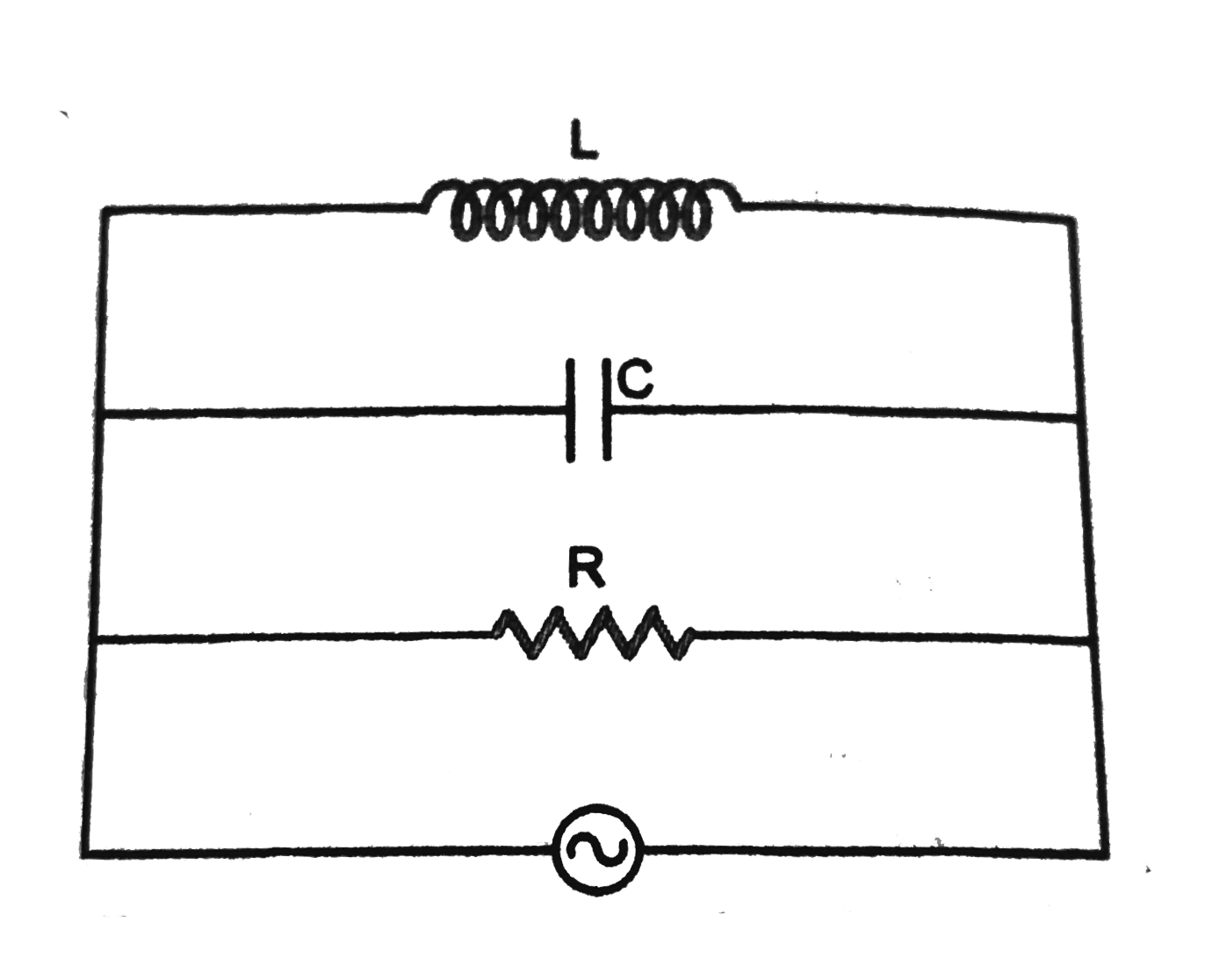
03:38View SolutionKeeping the source of frequency equal to the resonating frequency of the series LCR circuit, if the three elements L, C and R in are arranged in parallel , show that the total current in the parallel LCR circuit is a minimum at this frequency. Obtain the r.m.s. value of current in each brach of the circuit for the elements and source specified in for this frequency.
 06:27View Solution
What will be the instantaneous voltage for an a.c. supply of 230 V and 50 Hz?
01:13View SolutionThe instantaneous emf an a.c. source is given by `epsi=300 sin 314 t`. What is the rms value of the emf?
01:03View SolutionThe emf an source is given by the expression `epsi=300 sin 314 t`. Write the value of peak voltage and frequency of the source.
01:32View SolutionAn alternative current in amperes us given by `I=50 sin (400 pi t+phi)`. Find the frequency and the rms value of the current
01:45View SolutionAn alternating emf of peak value 350 V is applied across an a.c. ammeter of resistance `100 Omega`. What is the reading of the ammeter?
01:22View SolutionThe effective value of current in a 50 cycle a.c. circuit is 5 A. what is the value of current `1//300` second after it was zero?
01:20View SolutionThe peak value of an alternating current of frequency 50 Hz is 14.14 A. Find its rms value. How much time will the current take in reaching from 0 to maximum value.
01:25View SolutionA `100 Omega` iron is connected to a 220 V, 50 cycles wall plug. What is (i) peak potential difference (ii) average potential difference and (iii) rms current?
01:35View SolutionThe equation of a.c. in a circuit is `I=50 sin 100 pi t`. Find (i) frequency of a.c., (ii) mean value of a.c. over positive half cycle, (iii) rms value of current and (iv) the value of current `1//300` second after it was zero.
03:06View SolutionA resistance of `500 Omega` is connected to a source of emf, `epsi=10 sin 120 pi t` volt, time t is in second. Calculate (i) peak current (ii) virtual current and (iii) instantaneous current at `t=1/360` th of a second.
02:53View SolutionWhat is the inductive reactance of a coil if current through it is `800 mA` and the voltage across it is 40 V?
01:11View SolutionA 44 mH inductor is connected to 220 V, 50 Hz a.c. supply. Determine rms value of current in the circuit.
01:44View SolutionAn inductance of negligible resistance, whose reactance is 22 ohm at 200 Hz is connected to a 220 V V, 50 Hz power line. What is the value of inductance and reactance ?
04:33View SolutionA capactior of `1 mu F` is connected ot an a.c. source of e.m.f `E = 250 sin 100 pi t`. Write an equation for instantaneous current through the circuit and given reading of a.c. ammeter connected in the circuit.
04:29View SolutionA capacitor has a reactance of `100 Omega` at 50 Hz What will be its reactance at 125 Hz ?
03:15View SolutionThe virtual current in the a.c. circuit shown in fig, 14.15 is 1.0 A. Find (i) virtual coltage across the coil L (ii) impendance of the circuit and (ii) reactance of the coil.
 01:40View Solution
A `0.21 H` inductor and a `12 ohm` resistance are connected in series to a `220 V`. `50 Hz` ac source. Calculate the current in the circuit and the phase angle between the current and the source voltage.
04:50View SolutionAn e.m.f. `E = 200 sin 377 `t volt is applied across an inductance L having a resistance of 1.0 ohm. The maximum current is found to be 10 A. Find the value of L.
04:57View SolutionA circuit consists of a resistance 10 ohm and a capacitance of `0.1 mu F` If an alternating e.m.f. of 100 V. 50 Hz is applied, calculate the current in the circuit.
03:25View SolutionA 20 watt, 50 V lamp is connected in series to a.c. mains of 250 V, 50 Hz. Calculate to value of capacitor to run the lamp.
04:13View SolutionA resistor of 50 ohm, an inductor of `(20//pi)` H and a capacitor of `(5//pi) mu F` are connected in series to an a.c. source 230 V, 50 Hz. Find the current in the circuit.
04:19View SolutionA 40 ohm resistor, 3 mH inductor and `2 mu F` capacitor are connected in series to a 110 V, 5000 Hz a.c. source. Calculate the value of current in the circuit.
04:53View SolutionA `50 mu F` capacitor, 0.05 H inductor and `48 Omega` resistor are connected in series with an a.c. source of e.m.f. `E = 310 sin 314 t`. Calculate reactance of the circuit. What is its nature ?
What is phase angle between current and applied e.m.f. ?06:01View SolutionAn LCR series circuit with `L = 100 mH, C = 100 muF, R = 120 Omega` is connected to an `AC` source of `emf epsilon = (30 V) sin (100s^(-1))t`. Find the impedane, the peak current and the resonant frequency of the circuit.
08:15View SolutionA capacitor, resistor of `5 Omega`, and an inductor of `50 mH` are in series with an a.c. source marked `100 V, 50 Hz`. It is found that voltage is in phase with the current. Calculate the capacitance of the capacitor and the impedance of the circuit.
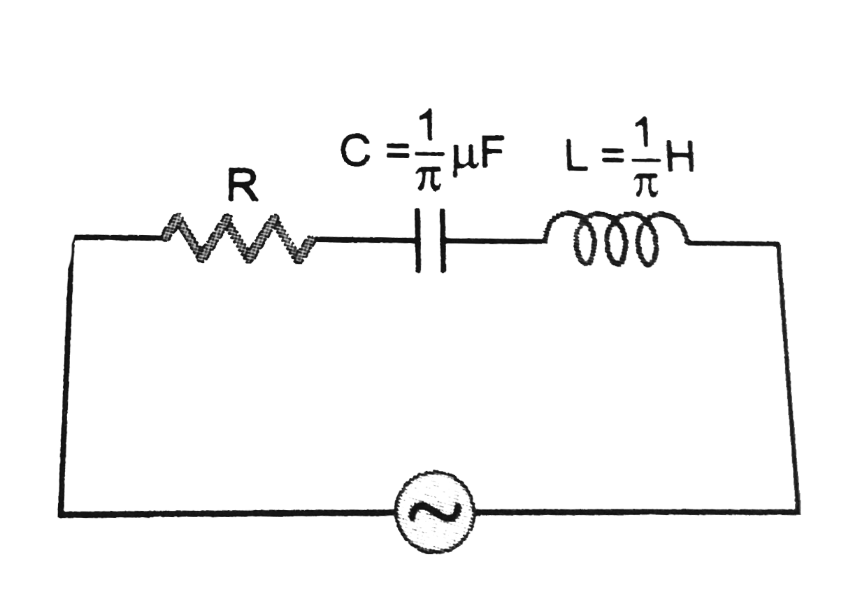
03:15View SolutionIn the a.c. circuit shown in fig, the main supply hs constant voltage but variable frequency. For what frequency will the voltage across the resistance R be maximum ?
 02:19View Solution
An a,c, source of frequency 50 hertz is connected to a 50 mH inductor and a bulb. The bulb glows with some brightness. Calculate the capacitance of the capacitor to be connected in series with the ciruit, so that the bulb glows with maximum brightness.
02:41View SolutionA `200km` long telegraph wire has capacitance of `0.014 mu F//km` If it carries an alternating current of `50 xx 10^(3)` Hz what should be the value of an inductance required to be connected in series in series so that impedance isw minimum .
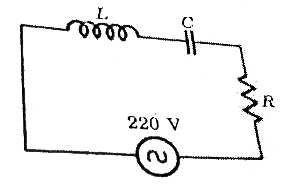
03:36View SolutionFig 14.18 shows a series LCR circuit connected to a variable frequency 200 V source:
`L=4.0H, C=100 muF` and `R=40 Omega`.
(i) Calculate the resonant frequency of the circuit.
(ii) Obtain the impedance of the circuit and the amplitude of the current at resonating frequency.
(iii) Determine r.m.s. potential drop across L.
 03:15View Solution
A 100 mH inductor, a `20 muF` capacitor and a 10 ohm resistor are connected in series to a `100 V, 50 Hz` a.c. source. Calculate : (i) Inpendance of the circuit at resonance (ii) Current at resonance (iii) Resonant frequency.
03:02View SolutionCompute the resonant frequency and the Q factor of a series LCR circuit having `L = 4.0 H, C = 36 mu F` and `R = (10)/(3) Omega`. How can sharpness of resonance of the circuit be improved by a factor of 2 by reducing its full width at half maximum ?
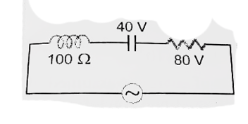
02:58View SolutionIn the circuit shown in fig. potential diff. across L, C and and R are given. Find the e.m.f. of the source and calculate power factor of the circuit.
 03:23View Solution
A 60 cycle AC circuit has a resistance of `200 Omega` and inductance of 10 mH. What is the power factor? What capacitance placed in the circuit will make the power factor unity?
04:17View SolutionA transformer has 300 primary turns and 2400 secondary turns: If the primary supply voltage is 230 V, what is the secondary voltage ?
02:32View SolutionA transformer has 200 primary turns and 150 secondary turns. If the operating voltage for the load connected to the secondary is measured to be 300 V, what is the voltage supplied to the primary ?
01:25View SolutionThe turns ratio of a transformer is 12.5. If its primary is connected with a.c. mains of 220 V, determine the voltage obtained across the secondary.
02:46View SolutionA step-up transfomer operates on a 220 volt line and supplies to load, a current of 2A. The ratio of primary and secondary winding is 1 : 25. Calculate secondary voltage, primary current and power output, if efficiency is 80%`
03:19View SolutionIn a stepup transformer, the ratio of number of turns in primary and secondary coils is `1 : 10`. What voltage will develop in the secondary if the primary is connected to 220 V mains ? If the current drawn from the secondary is 2A, calculate the current through the primary
03:01View SolutionCalculate current drawn by primary coil of a transformer, Which steps down 200 V to 20 V to operate a device of 20 ohm resistance. Assume efficiency of transformer 80 %.
03:18View SolutionThe output voltage of an ideal transformer, connected to a 240 V ac. when this transformer is used to light a bulb with rating 24 V, 24 W, calculate the current in the primary coil of the circuit.
02:02View SolutionA step down transformer is used at 220 V to provide a current of 0.5 A to a 15 W bulb. If the secondary has 20 turns, find the number of turns in primary coil has current that flows in primary coil.
02:58View SolutionA step down transformer converts transmission line voltage from 2200 V to 220 V. Primary coil is having 5000 turns. Efficiency of transformer is 90% and output power is 8 kW. Evaluate number of turns in secondary coil and input power.
02:49View SolutionThe number of turns in the primary and secondary coils of an ideal transformer are 2000 and 50 respectively. The primary coil is connected to a main supply of 120 V and secondary to a night bulb of `0.6 Omega`. Calculate
(i) Voltage across the secondary. (ii) Current in the bulb, (iii) Current in primary coil, (iv) Power in primary and secondary coils, (iv) Power in primary and secondary coils.03:52View SolutionThe primary of a transformer has 200 turns and secondary has 1000 turns. The power output from secondary at 1000 V is 9 kW. Calculate primary voltage and heat loss in primary. Take resistance of primary coil `0.2 Omega` and efficiency of transformer = 90%.
03:35View SolutionAn a.c generator consists of a coil of 50 turns and area `2.5 m^(2)` rotating at an angular speed of `60 rad//s` in a uniform magnetic field of 0.30 T. The resistance of the circuit is 500 ohm. What is the maximum current drawn from the generator? What is the flux through the coil, when current is zero and when current is maximum ?
03:40View SolutionA generator develops an e.m.f. of 120 V and has a terminal potential difference of 115 V, when the amature current is 25 A. What is the resistance of the armature ?
01:19View Solution
problem questions and complete solutions for chapter AC CIRCUITS AND ELECTRIC CIRCUITS of DHANPAT RAI & CO PHYSICS (HINGLISH) of Class 12
