Complete Solutions to Problems of chapter CIRCUITS of Class 12 book with complete answers and questions
| Class 12 | PHYSICS |
| Chapter | CIRCUITS |
| RESNICK AND HALLIDAY | Problems |
| Number Of Questions | 45 |
| Academic Year | 2023-24 |
An isolated charged capacitor may gradually discharge as charge leaks from one plate to the other through the intermediate material, as if it were discharging through an external resistor. (a) What is the resistance of such an external resistor if a `2.00 muF` capacitor's potential difference decreases to 60.0% of its initial value of 50.0 V in 2.40 d? (b) What is the corresponding loss of potential energy in that time interval? (c) At the end of that interval, at what rate is the capacitor losing potential energy?
View SolutionIn Fig. 27-37, the ideal batteries have emfs `epsi_(1)= 12.0 V and = epsi_(2)=0.500 epsi_(1)` and the resistances are each `4.00 Omega`. What is the current in (a) resistance 2 and (b) resistance 3?
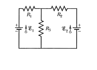
View SolutionIn Fig 27.37, `epsi_(1)=1.00V, epsi_(2)=3.00 V, R_(1)=4.00 Omega, R_(2)=2.00 Omega, R_(3)=5.00 Omega`, both batteries are deal. What is the latest which energy is dissipated in (a) `R_1, (b) R_2 and (c) R_3?` What is the power of (d) battery 1 and (e) ballery 2? Is energy being absorbed or provided in (f) battery and (g) battery 2?
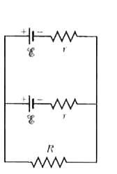
View SolutionIn Fig. 27-38, two batteries with an emf `epsi= 12.0 V` and an internal resistance r=0.500 `Omega` are connected in parallel across a resistance R. (a) For what value of R is the dissipation rate in the resistor a maximum? (b) What is that maximum? and (c) what is the total dissipation rate in the batteries? In terms of r, what are (d) the effective R (internal) resistance of the two-battery system and (e) the resistance R that is required to maximize the dissipation rate? This is a general result.
View SolutionIn Fig. 27-39, a voltmeter of resistance `R_v= 300 Omega` and ammeter of resistance `R_A= 3.00 Omega` are being used to measure a resistance R in a circuit that also contains a resistance `R_(0) =100 Omega` and an ideal battery with an emf of `epsi = 18.0 V.` Resistance R is given by R =V/i, where V is the potential across R and i is the ammeter reading. The voltmeter reading is V', which is V plus the potential dilference across the ammeter. Thus, the ratio of the two meter readings is not R but only an apparent resistance R' -V/i. If R `=85.0Omega` what are (a) the ammeter reading.
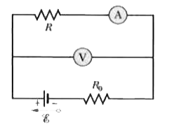
(b) the voltmeter reading, and (c) R'? (a) If `R_A` is decreased, does the difference between R' and R increase, decrease, or remain the same?
View SolutionIn Fig. 27-40, `R_1= 100 Omega, R_2=R_3= 50.00Omega, R_4 = 75.0 Omega,` and the ideal battery has emf `epsi= 12.0 V.` (a) What is the equivalent resistance? What is i in (b) resistance 1, (c) resistance 2,(d) resistance 3, and (e) resistance 4?
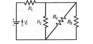
View SolutionIn Fig. 27-40, the resistors have the values `R_1= 700 Omega, R_2 =12.0 Omega, and R_3= 4.00Omega` and the ideal battery's emf is 22.0 V. For what value of `R_4` Will the rate at which the battery transfers energy to the resistors equal (a) 60.0 W, (b) the maximum possible rate `P_(max) and` and (c) the minimum possible rate `P_("min")?` What are (d) `P_(max) and (e) P_("min")?`
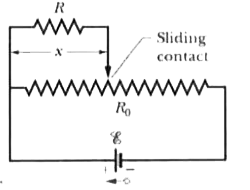
View SolutionFigure 27-41 shows a battery connected across a uniform resistor `R_0.` A sliding contact can move across the resistor from x=0 at the left x= 10 cm at the right. Moving the contact changes how much resistance is to the left of the contact and how much is to the right. Find the rate at which energy is dissipated resistor R as a function of x. Plot the function for `epsi_(0)=50V, R=2000 Omega and R_(0)=100 Omega`
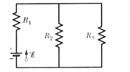
View SolutionIn Fig. 27-42, the resistances are `R_1=3.00 Omega, R_2= 700 Omega.` and the battery is ideal. What value of `R_3` maximizes the dissipation rate in resistance 3?
View SolutionA capacitor with an initial potential difference of 80.0 V is discharged through a resistor when a switch between them is closed at t=0. At t= 10.0s, the potential difference across the capacitor is 1.00V (a) What is time constant of the circuit? (b) What is the potential difference across the capacilor
View SolutionIn Fig. 27-43, the current in resistance 6 is `i_(6)= 2.80 A` the resistances are `R_(1)=R_(2)=R_(3)=2.00 Omega, R_(4)=16.0 Omega, R_(5)=8.00 Omega and R_(6)=4.00 Omega`. Wat is the emf of the ideal battery?

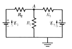
View SolutionIn Fig. 27-44, `epsi_(1)=8.00 V, epsi_(2)=12.0V, R_(1)=100 Omega, R_(2)=200Omega, R_(3)=300 Omega`. One point of the circuit is grounded (V =0). What are the (a) size and (b) direction (up or down) of the current through resistance 1, the (c) size and (d) direction (left or right) of the current through resistance 2, and the (e) size and (f) direction of the current through resistance 3? (g) What is the electric potential at point A?
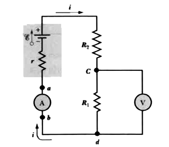
View SolutionIn Fig. 27-45, assume that `epsi= 3.0 V, r = 100 Omega, R_(1)=250 22 and R_2= 300 Omega`. If the voltmeter resistance RV is `5.0 kOmega.` what percent error does it introduce into the measurement of the potential difference across `R_1?`. Ignore the presence of the ammeter.
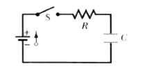
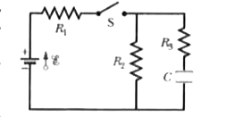
View SolutionSwitch S in Fig. 27-46 is closed at time t= 0, to begin charging an initially uncharged capacitor of capacitance `C= 49.0 muF` through a resistor of resistance `R = 32.0Omega.` At what time is the potential across the capacitor equal to that across the resistor?
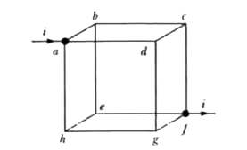
View SolutionIn the circuit shown in Fig. 27-47, there is a cube of resistances which are all having the same resistance of R. Find the equivalent resistance of the network between diagonally opposite points as shown in the figure.
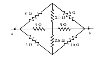
View SolutionFind the equivalent resistance of the network as shown in Fig 27.48 between points a and b
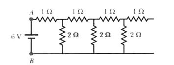
View SolutionAn infinite ladder is constructed with `1 Omega and 2 Omega` resistors as shown in Fig 27-49. Find the effective resistance between the points A and B.
View SolutionIn Fig 27-50,` epsi=24.0 V, R_(1)=2000 Omega, R_(2)=3000 Omega and R_(3)=4000 Omega`. What are the potential differences (a) `V_(A)-V_(B)` (b) `V_(B)-V_(C)` (c) `V_(C)-V_(D) and (d) V_(A)-V_(C)?`
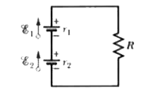
View SolutionIn Fig. 27-51. battery 1 has emf `epsi_(1)= 12.0 V` and internal resistance `r_1= 0.025 Omega` and battery 2 has `emf_(2)= 12.0 V` and internal resistance `r_2= 0.012Omega`. The batteries are connected in series with an external resistance R. (a) What R value makes the terminal-to-terminal potential difference of one of the batteries zero? (b) Which battery is that?
View SolutionA capacitor with initial charge `q_0,` is discharged through a resistor. What multiple of the time constant `tau` gives the time the capacitor takes to lose (a) the first 25% of its charge and (b) 50% of its charge?
View SolutionIn Fig 27-52, circuit section AB absorbs energy at a rate of 50W when current i=2.0A through it is in the indicated direction. Resistance `R=2.0 Omega`, (a) What is the potential difference between A and B? Emf device X lacks internal resistance. (b) What is its emf? (c) is pont B connected the positive terminal of X or to the negative terminat?

View SolutionSixteen copper wires of length I and diameter d are connected in parallel to form a single composite conductor of resistance R. What must the diameter D of a single copper wire of length I be if it is to have the same resistance?
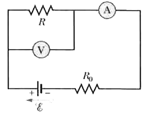
View SolutionIn Fig 27-53, a voltmeter of resistance `R_(v)=300 Omega` and an ammeter of resistance `R_A= 3.00 Omega` are being used to measure a resistance R in. a circuit that also contains a resistance `R_0= 100 Omega` and an ideal battery of emf `epsi= 28.5 V.` Resistance R is given by R=V//i where V is the voltmeter reading and i is the current in resistance R. However, the ammeter reading is not i but rather i', which is i plus the current through the voltmeter. Thus, the ratio of the two meter readings is not R but only an apparent resistance R'=V/I'. If `R=85.0 Omega` what are (a) the ammeter reading. (b) the voltmeter reading, and (c) R' (d) If `R_v` is increased does the difference between R' and R increase, decrease or on the same?
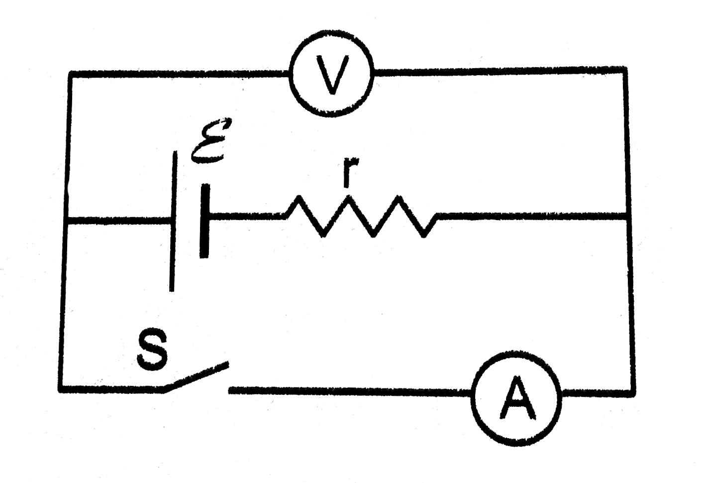
View SolutionShown an arrangement to measure the emf `(epsilon)`and internal resistance r of a battery. The voltmeter has a very high resistance and the ammeter also has some resistance.The voltmeter reads 1.52 V when the switch S is open.When the switch is closed the voltmeter reading drops to 1.45 V and the ammeter read 1.0A Find the emf and the internal resistance of the battery.
View SolutionA voltmeter consists of a `25Omega` coil connected in series with a `575 Omega` resistor. The coil takes 10 mA for full-scale deflection. What maximum potential difference can be measured on this voltmeter?
View SolutionAn ammeter is to be constructed which can read currents up to 2.0 A. Iſ the coil has a resistance of `25Omega` and takes 1 mA for full-scale deflection, what should be the resistance of the shunt used?
View SolutionA volmeter coil has resistance `50.0 Omega` and a resistor of `1.15 k Omega` is connected in series. It can read potential differences upto 12 V. If this same coil is used to construct an ammeter which can measure currents up to 2.0 A, what should be the resistance of the shunt used?
View SolutionA `3.00 M Omega` resistor and a `1.00 muF` capacitor are connected in series with an ideal battery of emf `epsi= 4.00 V. ` At 6.00 s after the connection is made, what is the rate at which (a) the charge of the capacitor is increasing, (b) energy is being stored in the capacitor, (c) thermal energy is appearing in the resistor, and (d) energy is being delivered by the battery?
View SolutionIn an RC series circuit, emf `epsi= 12.0 V,` resistance `R =1.40 MOmega` and capacitance `C= 2.70 muF.` (a) Calculate the time constant. (b) Find the maximum charge that will appear on the capacitor during charging. (C) How long does it take for the charge to build up to `16.0 muC?`
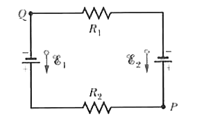
View SolutionIn Fig 27-56, the ideal batteries have emf `emf_(1)2=200V and epsi_(2)=50V` and the resistances are `R_(1)=3.0 Omega and R_(2)=2.0 Omega`. If the potential at P is 100 V, what is at at Q?
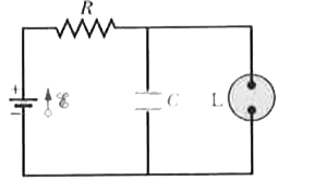
View SolutionFigure 27-56 shows the circuit of a flashing lamp, like those attached to barrels at highway construction sites. The fluorescent lamp L (of negligible capacitance) is connected in parallel, across the capacitor C of can RC circuit. There is a current through the lamp only when it potential difference across it reaches the breakdown voltage `V_(L)`, then the capacitor discharges completely through the lamp and the lamp flashes briefly. For a lamp with breakdown voltage `V_L= 75.0 V,` wired to a 95.0 V ideal battery and a `0.150 muF` capacitor, what resistance R is needed for two flashes per second?
View SolutionSix `18.0Omega` resistors are connected in parallel across a 12.0V ideal battery. What is the current through the battery?
View SolutionIn Fig. 27-9, what is the potential difference `V._d -V_c` between points d and c if `epsi_(1)= 4.0 V. epsi_(2) - 1.0 V, R_1= R_2= 10Omega, and R_3= 8.0 Omega,` and the battery is ideal?
View SolutionIn the circuit of Fig 27-57 `epsi=1.2kV, c=6.5muF, R_(1)=R_(2)=R_(3)=0.73 M Omega`. With C completely uncharged switch S is suddenly closed (at t=0). At t=0, what are (a) current `i_(1)` in resistor 1, (b) current `i_(2)` in resistor 2, and (c) current `i_(3)` in resistor 3? At `t=oo` (thta is after many time constants). what are (d) `i_(1), (e) i_(2) and (f) i_(3)?` What is the potential difference `V_(2)` across resistor 2 at (g) t=0 and (h) `t=oo?` Sketch `V_(2)` versus t between these two extreme times.
View SolutionWhen resistors 1 and 2 are connected in series, the equivalent resistance is `20.0 Omega.` When they are connected in parallel, the equivalent resistance is `3.75 Omega.` What are (a) the smaller resistance and (b) the larger resistance of these two resistors?
View SolutionA car battery with a 12 V emf and an internal resistance of `0.030 Omega` is being charged with a current of 40 A. What are (a) the potential difference V across the terminals, (b) the rate `P_r.` of energy dissipation inside the battery, and (c) the rate `P_("emf")` of energy conversion to chemical form? When the battery is used to supply 40 A to the starter motor, what are (d) V and (e) P?
View SolutionIn Fig. 27-58, `R_1= R_2, 4.00 Omega and R_3= 1.50Omega.` Find the equivalent resistance between points D and E. (Hint : Imagine that a battery is connected across those points).

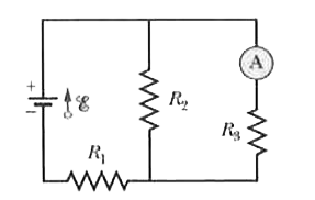
View SolutionIn Fig 27-59, what current does the ammeter read if `epsi=5.0V` (ideal battery), `R_(1)=2.0 Omega, R_(2)=9.0 Omega and R_(3)=6.0 Omega?` (b) The ammeter and battery are now interchanged. Show that are ammeter reading is unchanged.
View SolutionA total resistance of `5.00 Omega` is to be produced by connecting an unknown resistance. a) What must be the value of the unknown resistance and (b) should it be connected in series or in parallel (c) What is the total resistance if the unknown resistance is connected the other way?
View SolutionA 5.7 A current is set up in a circuit for 15.0 min by a rechargeable battery with a 6.0 V emf. By how much is the chemical energy of the battery reduced?
View SolutionThe potentiometer wire `AB` is `600` cm long.
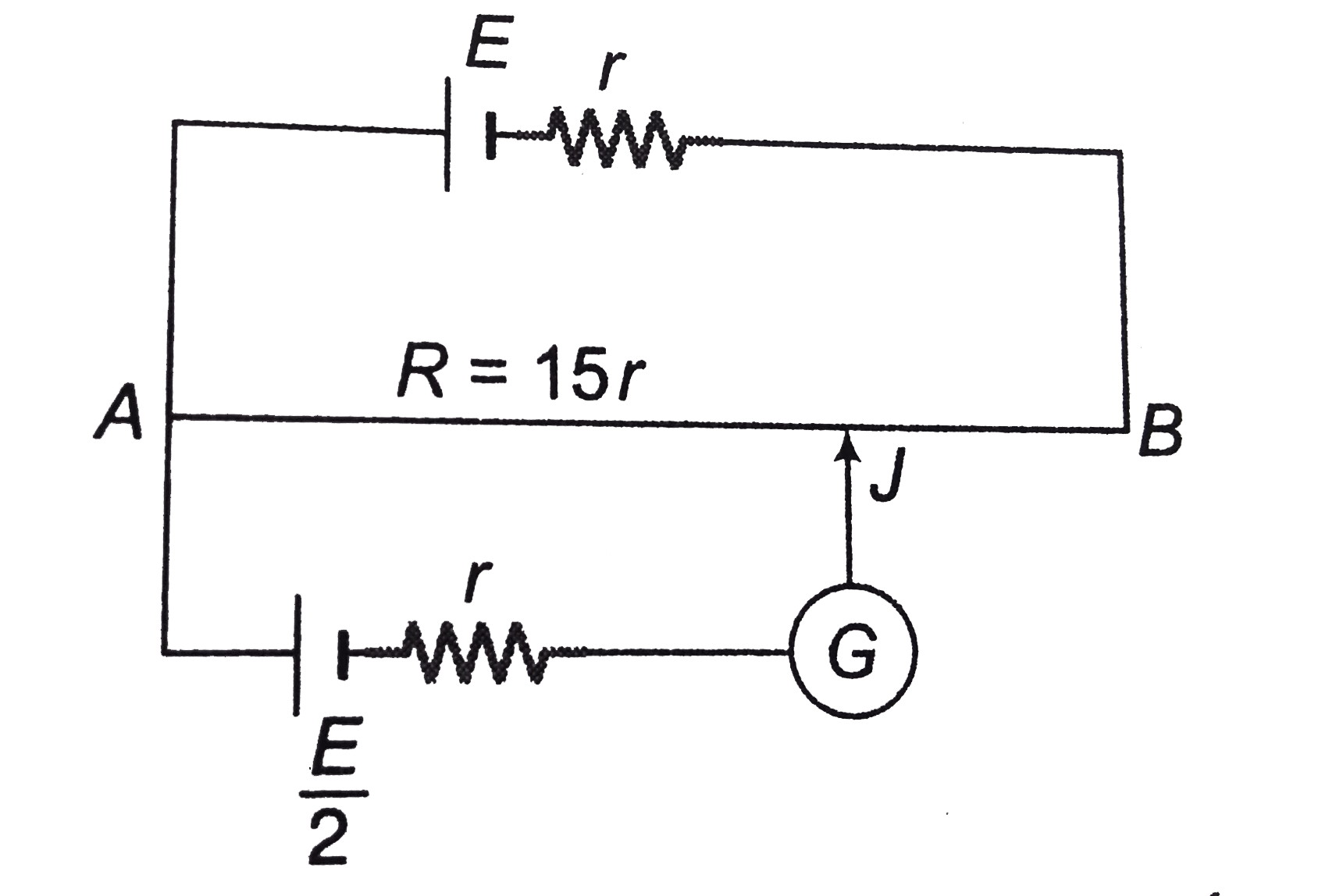 a. At what distance from A should be jockey `J` touch the wire to get zero deflection i the galvanometer.
b. If the jockey touches the wire at a distance `560 cm` from A, what will be the current through the galvanometer.
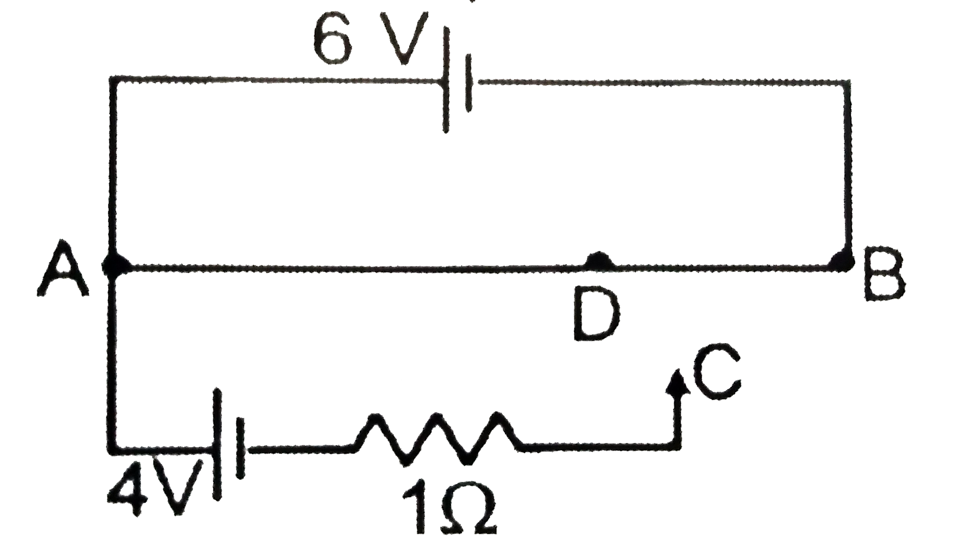
View SolutionA 6 volt battery of negligible internal resistance is connected across a uniform wire AB of length `100 cm`. The positive terminal of another battery of emf 4V and internal resistance `1 Omega` is joind to the point A as shown in figure. Take the potential at B to be zero. (a) What are the potentials at the points A and C ? (b) At which D of the wire AB, the potential is equal to the potential at C. ( c) If the point C and D are connected by a wire. What will be the current through is ? (d) Id the 4V batteryt is replaced by 7.5 V battery, what whould be the answers of parts (a) and (b) ?
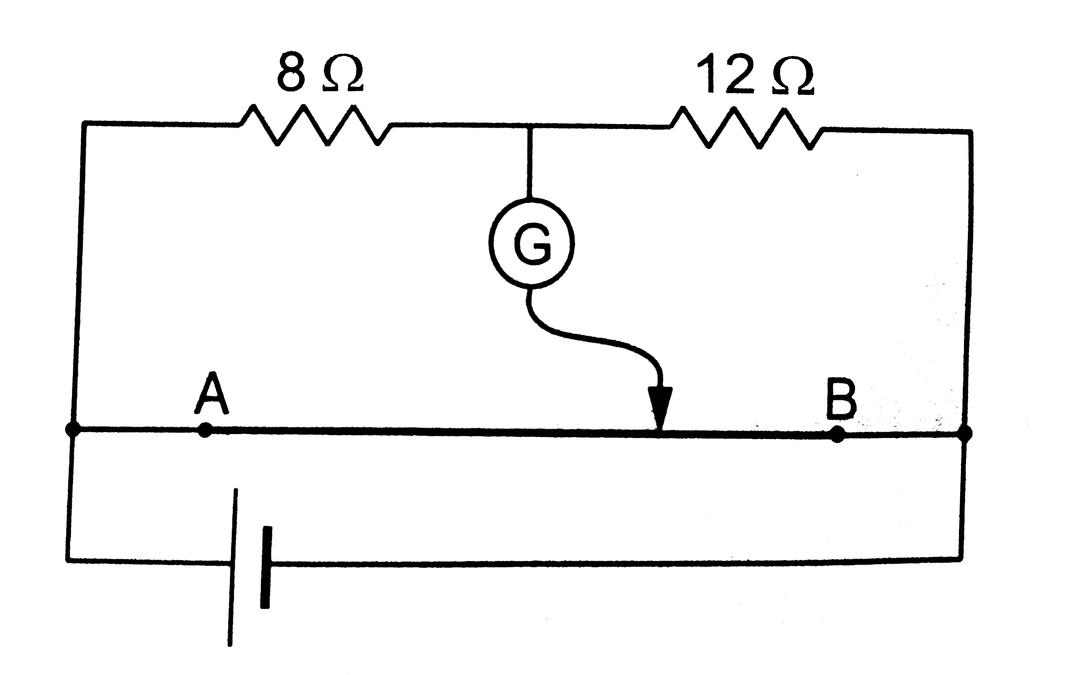
View SolutionThe potentiometer wire AB shown in figure is 40 cm long. Where should the free end of the galvanometer be connected on AB so that the galvanometer may show zero deflection?
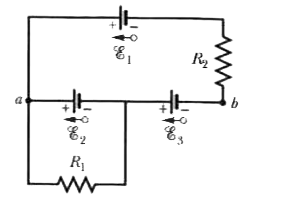
View SolutionIn Fig. 27-63, `R_1=100 Omega, R_2= 50 Omega,` and the ideal batteries have emfs, `epsi_(1)=6.0 V, epsi_(2)= 10 V, and epsi_(3) =4.0 V.` Find (a) the current in resistor 1, (b) the current in resistor 2, and (c) the potential difference between points a and b.
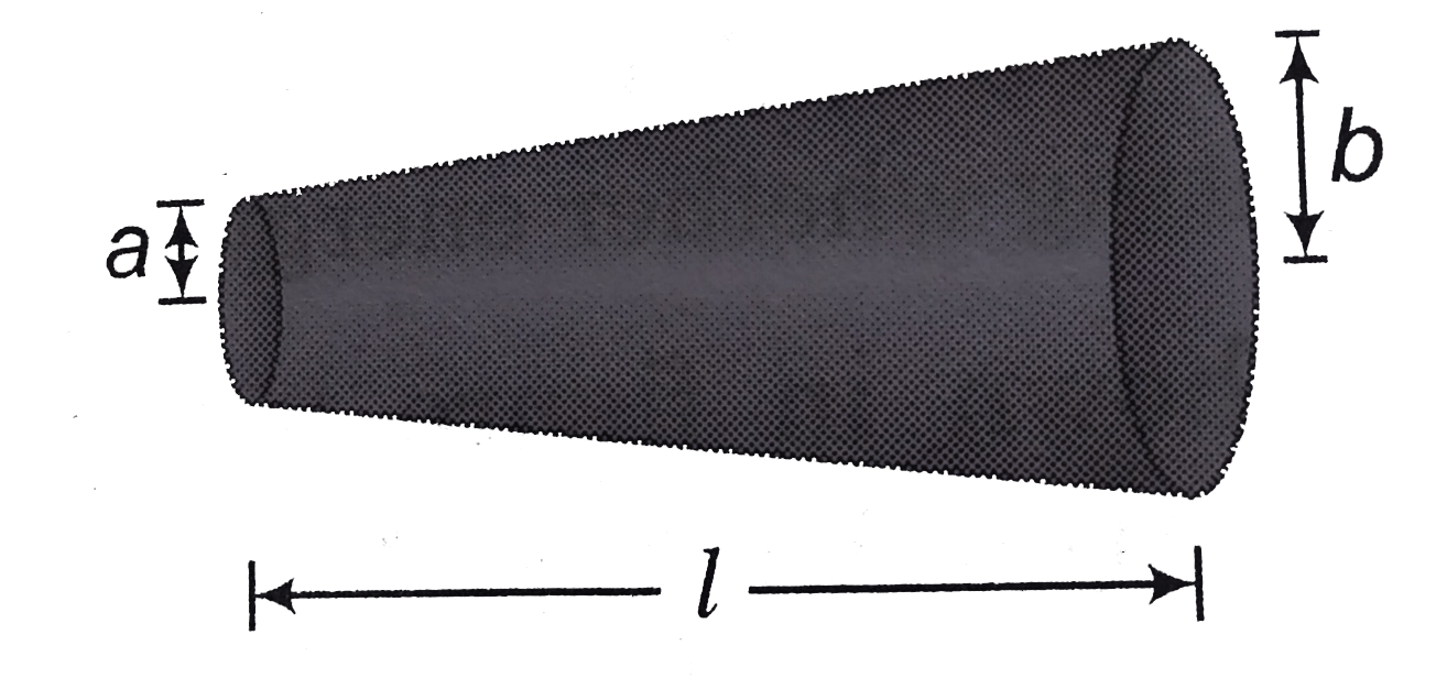
View SolutionA conductor of length `l` has a non-uniform cross-section. The radius of cross-section varies linearly from `a` to `b`. The resistivity of the material is `rho`. Find the resistance of the conductc across its ends.
View Solution
Problems questions and complete solutions for chapter CIRCUITS of RESNICK AND HALLIDAY PHYSICS (HINGLISH) of Class 12