Complete Solutions to Exercises Linked Comprehension of chapter ELECTROMAGNETIC INDUCTION of Class 12 book with complete answers and questions
| Class 12 | PHYSICS |
| Chapter | ELECTROMAGNETIC INDUCTION |
| CENGAGE PHYSICS | Exercises Linked Comprehension |
| Number Of Questions | 36 |
| Academic Year | 2023-24 |
A flexible circular loop `20cm` in diameter lies in a magneic field with magnitude `1.0 T`, direction lies into the plane of the page as shown in Fig. 3.187. The loop is pulled at the points indicated by the arrws, forming a loop of zero area in `0.314s`.
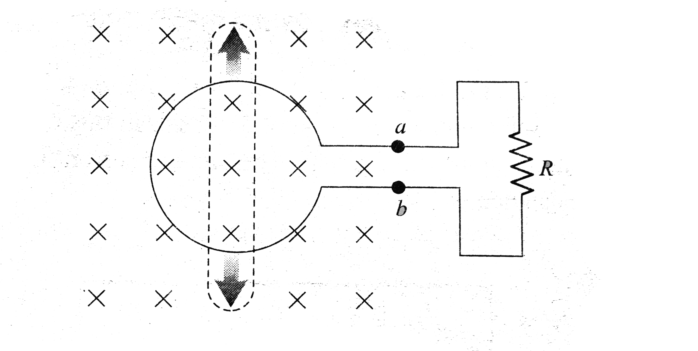
The average induced emf in the circuit is02:57View SolutionA flexible circular loop `20cm` in diameter lies in a magneic field with magnitude `1.0 T`, direction lies into the plane of the page as shown in Fig. 3.187. The loop is pulled at the points indicated by the arrws, forming a loop of zero area in `0.314s`.
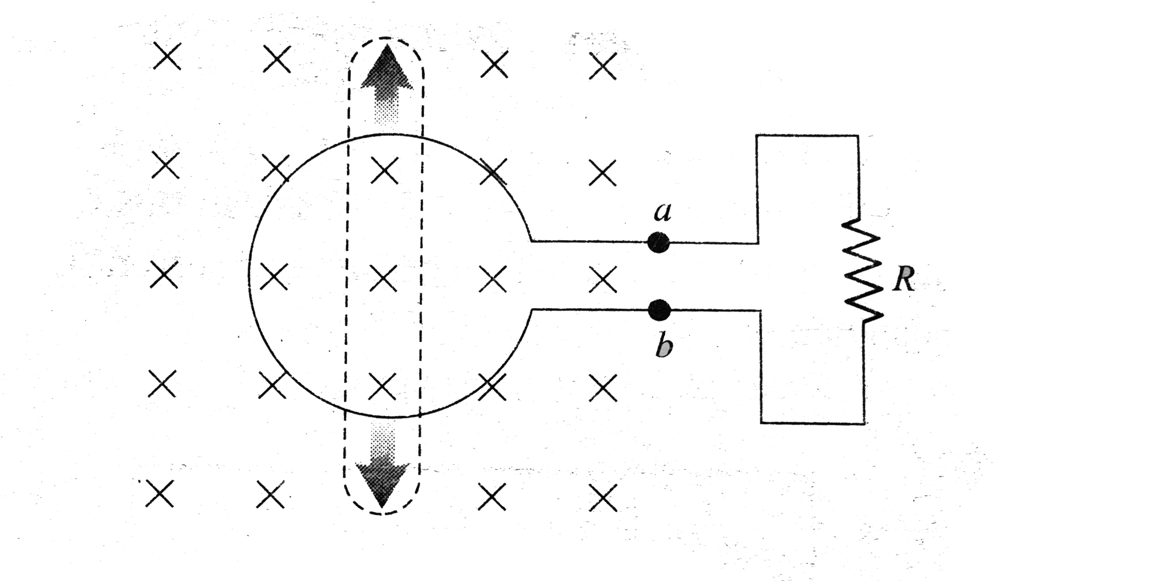
if `R = 0,01 Omega`, the magnitude and direction of current flowing in the loop are04:34View SolutionFigure. shows two parallel and coaxial loops. The smaller loop (radius r) is above the larger loop (radius R), by distance `x gtgt R`. The magnetic field due to current `i` in the larger loop is nearly constant throughout the smaller loop. Suppose that `x` is increasing at a constant rate of `dx//dt = v`.
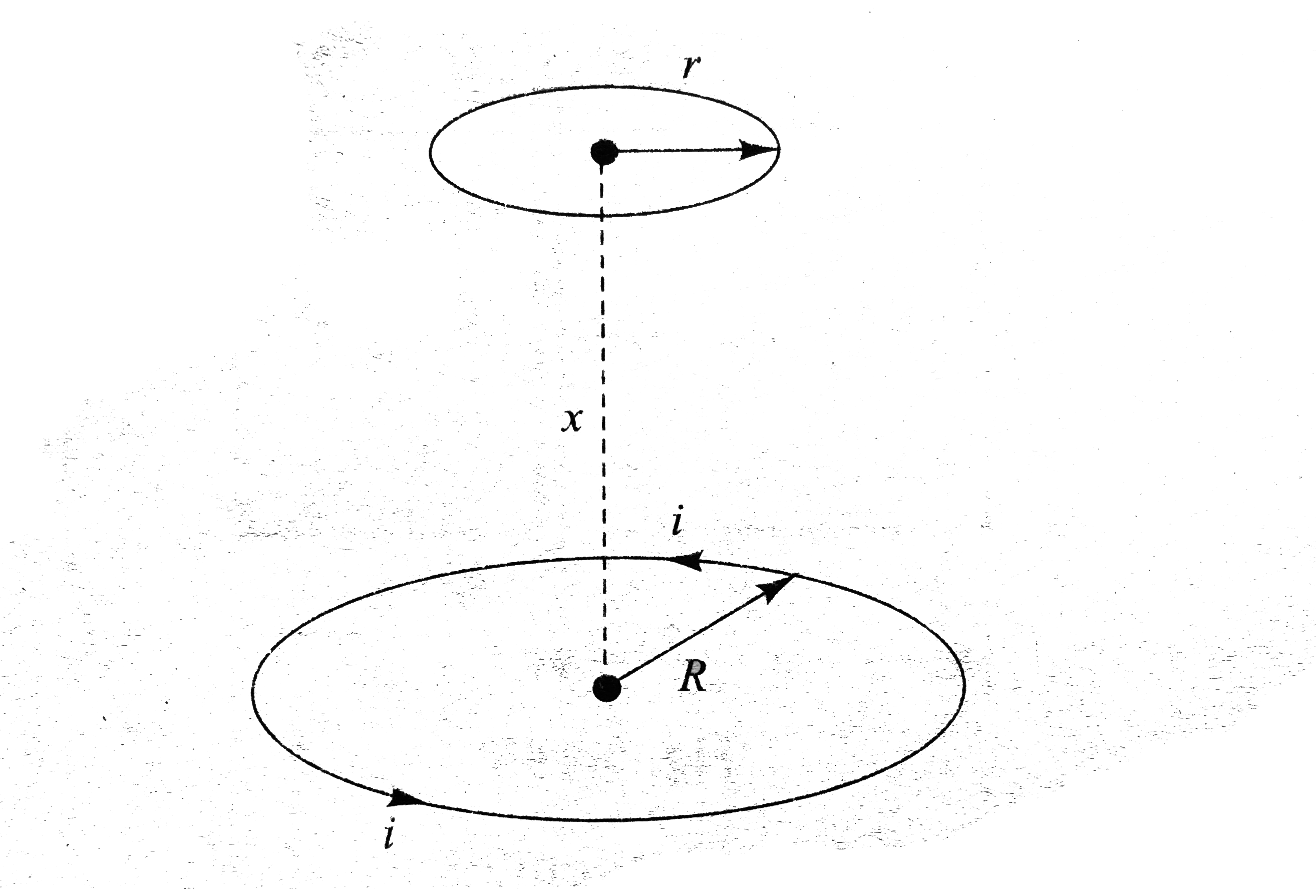
Determine the magneitc flux through the smaller loop as a function of `x`.03:35View SolutionFigure 3.188 shows two parallel and coaxial loops. The smaller loop (radius r) is above the larger loop (radius R), by distance `x gtgt R`. The magnetic field due to current `i` in the larger loop is nearly constant throughout the smaller loop. Suppose that `x` is increasing at a constant rate of `dx//dt = v`.
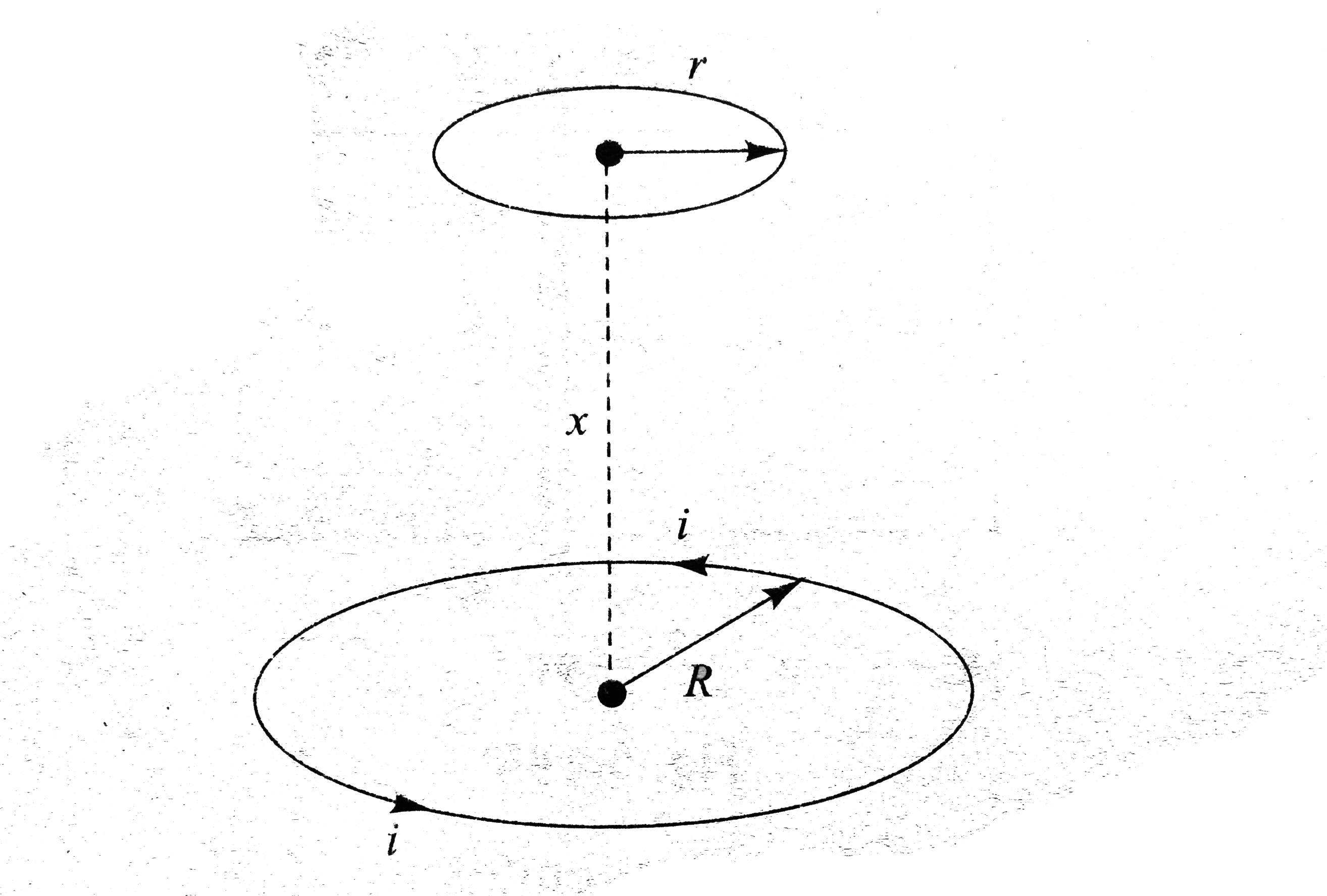
The induced emf in the smaller loop is05:17View SolutionA wire loop enclosing a semicircle of radius `R` islocated on the boundary of a uniform magnetic field `B`. At the moment `t = 0`, the loop is set into rotation with constant angular acceleration `alpha` about an axis `O`. The clockwise emf direction is taken to be positive.
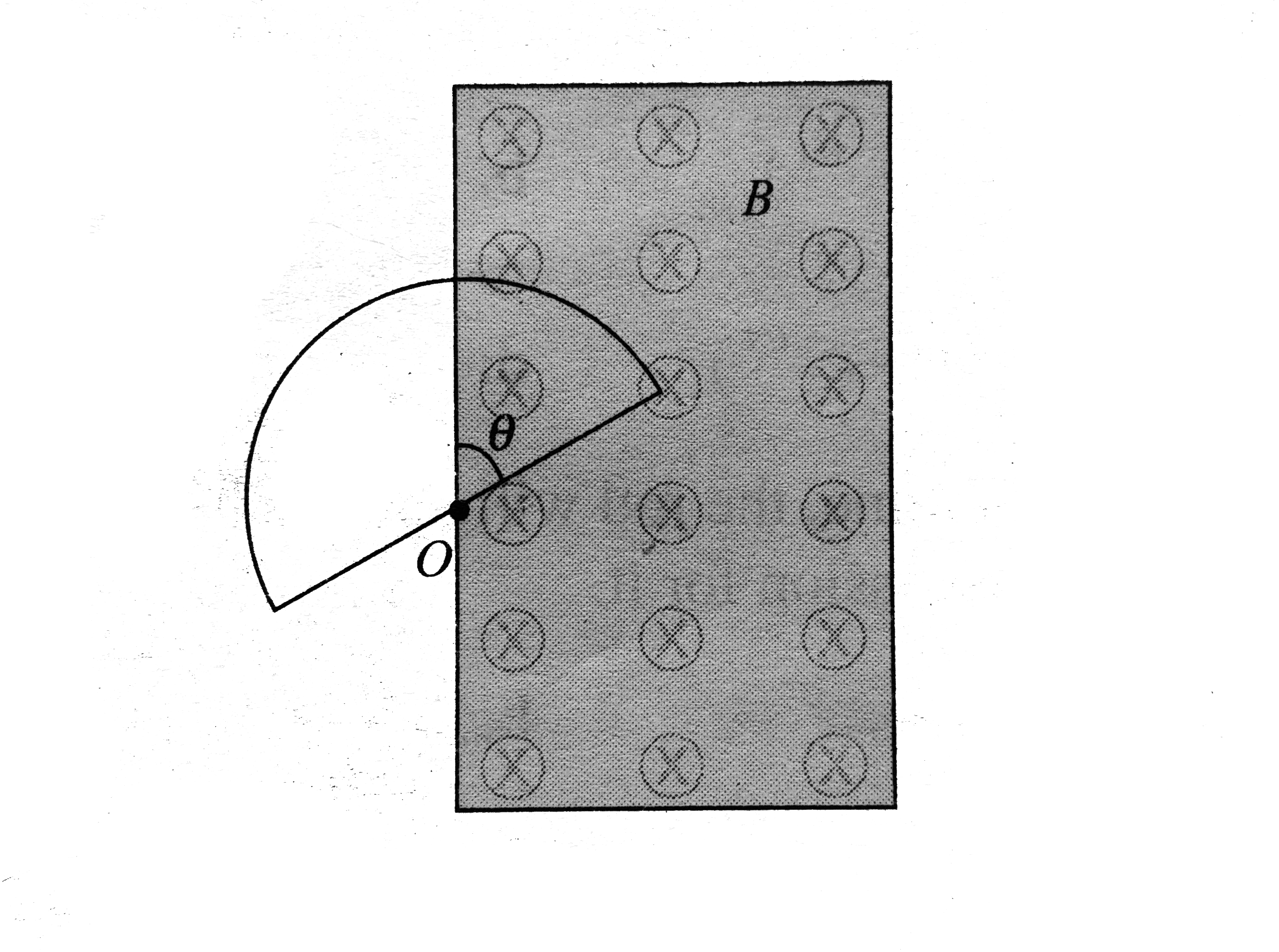
The variation of emf as function of time is04:28View SolutionA wire loop enclosing a semicircle of radius `R` islocated on the boundary of a uniform magnetic field `B`. At the moment `t = 0`, the loop is set into rotation with constant angular acceleration `alpha` about an axis `O`. The clockwise emf direction is taken to be positive.
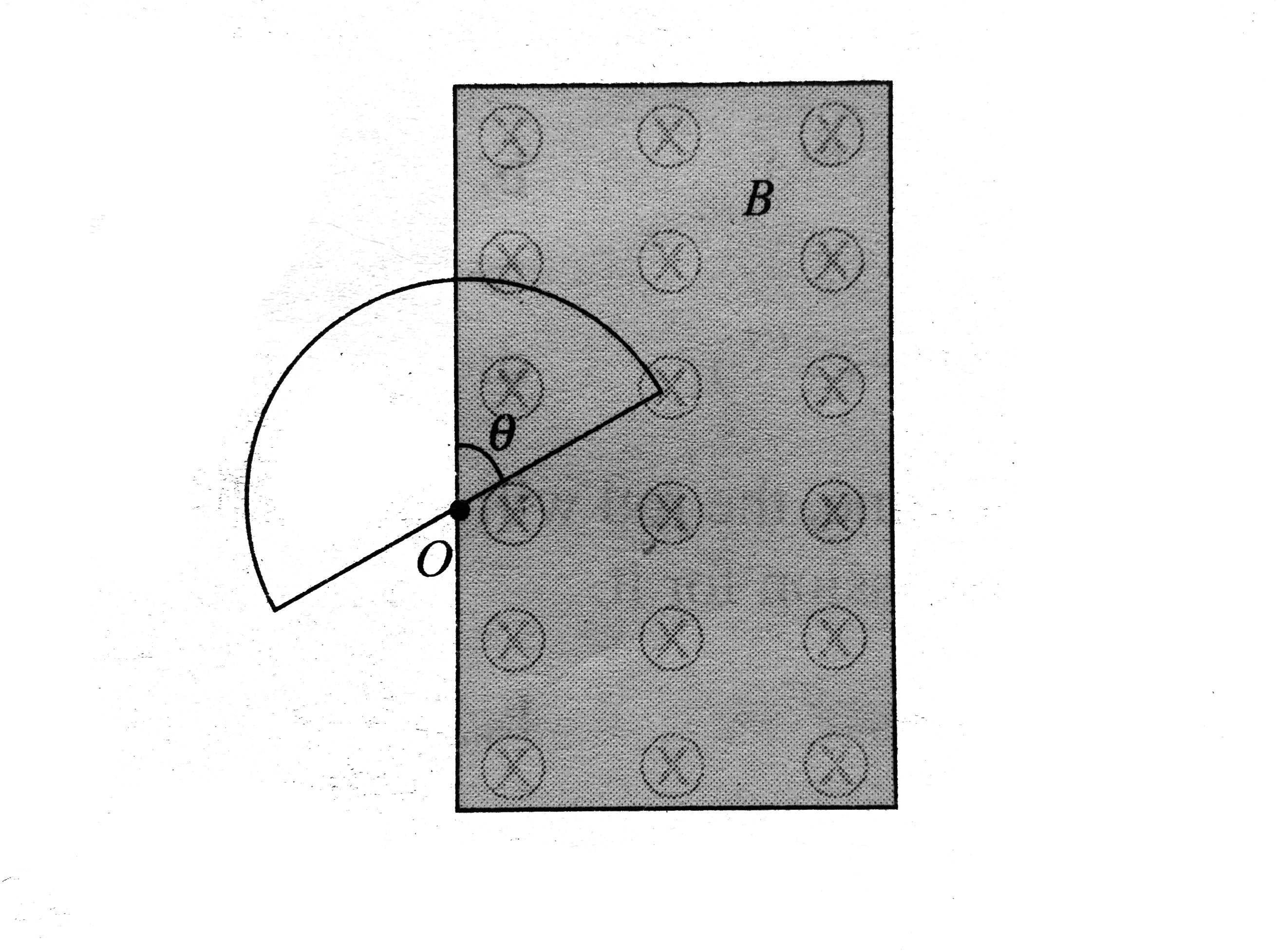
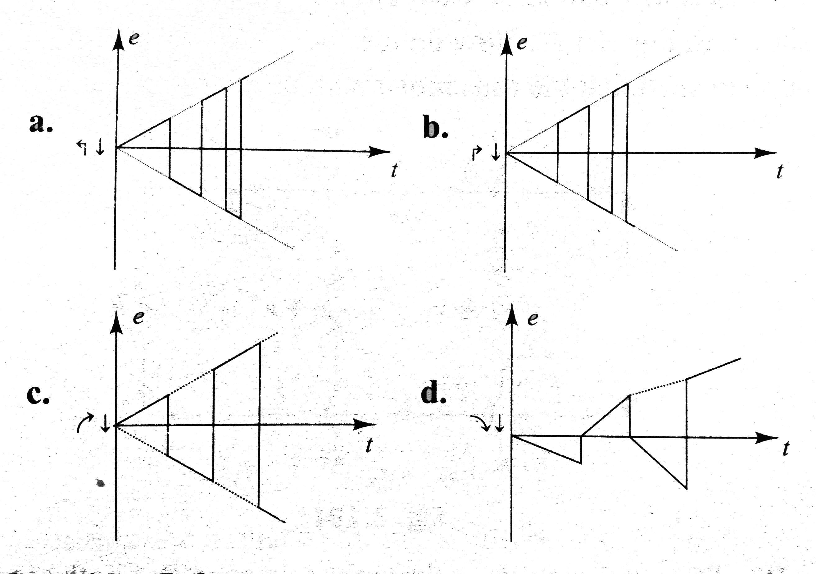
The variation of emf as a function of time is07:08View SolutionIn the circuit shown in Fig. the capacitor has capacitance `C = 20 muF` and is initially charged to `100 V` with the polarity shown. The resistor `R_(0)` has resistance `10 Omega`. At time `t = 0`, the switch is closed. The smaller circuit is not connected in any way to teh larger one. the wire of the smaller circuit has a resistance of `1.0 Omega m^(-1)` and contains `25` loops. the larger circuit is a rectangle `2.0 m` by `4.0 m`, while the smaller one has dimensions `a = 10.0 cm` and `b = 20.0 cm`. the distance `c`is `5.0 cm`. (The figure is not drawn to scale.) Both circuit are held stationary. Assume that only the wire nearest to teh smaller circuit produces. an appreciable magnetic field through it.
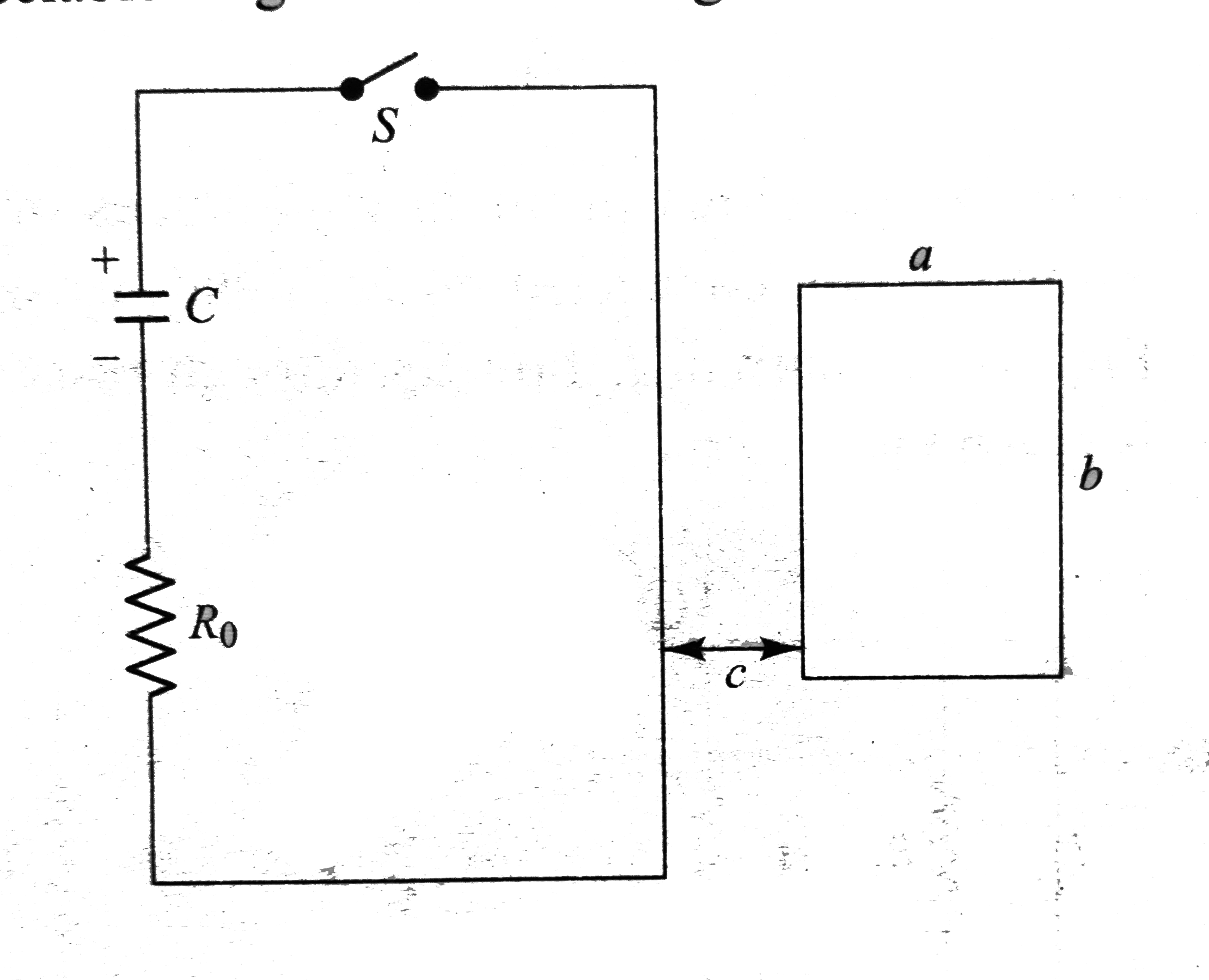
The current in the circuit `200 ms` after closing `S` isView SolutionIn the circuit shown in Fig. the capacitor has capacitance `C = 20 muF` and is initially charged to `100 V` with the polarity shown. The resistor `R_(0)` has resistance `10 Omega`. At time `t = 0`, the switch is closed. The smaller circuit is not connected in any way to teh larger one. the wire of the smaller circuit has a resistance of `1.0 Omega m^(-1)` and contains `25` loops. the larger circuit is a rectangle `2.0 m` by `4.0 m`, while the smaller one has dimensions `a = 10.0 cm` and `b = 20.0 cm`. the distance `c`is `5.0 cm`. (The figure is not drawn to scale.) Both circuit are held stationary. Assume that only the wire nearest to teh smaller circuit produces. an appreciable magnetic field through it.
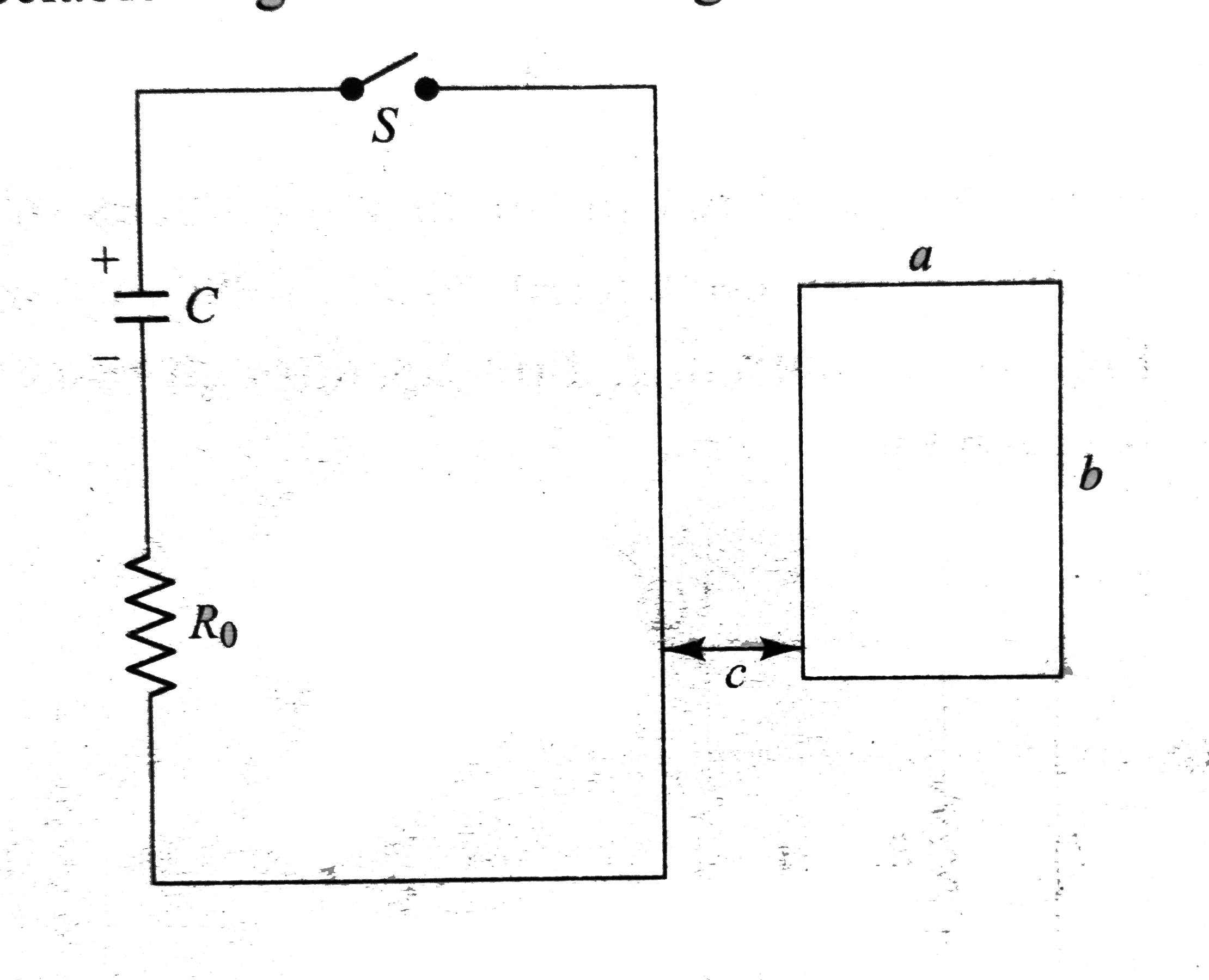
The curent in the smaller circuit `200 mus` after closing `S` isView SolutionIn the circuit shown in Fig. the capacitor has capacitance `C = 20 muF` and is initially charged to `100 V` with the polarity shown. The resistor `R_(0)` has resistance `10 Omega`. At time `t = 0`, the switch is closed. The smaller circuit is not connected in any way to teh larger one. the wire of the smaller circuit has a resistance of `1.0 Omega m^(-1)` and contains `25` loops. the larger circuit is a rectangle `2.0 m` by `4.0 m`, while the smaller one has dimensions `a = 10.0 cm` and `b = 20.0 cm`. the distance `c`is `5.0 cm`. (The figure is not drawn to scale.) Both circuit are held stationary. Assume that only the wire nearest to teh smaller circuit produces. an appreciable magnetic field through it.
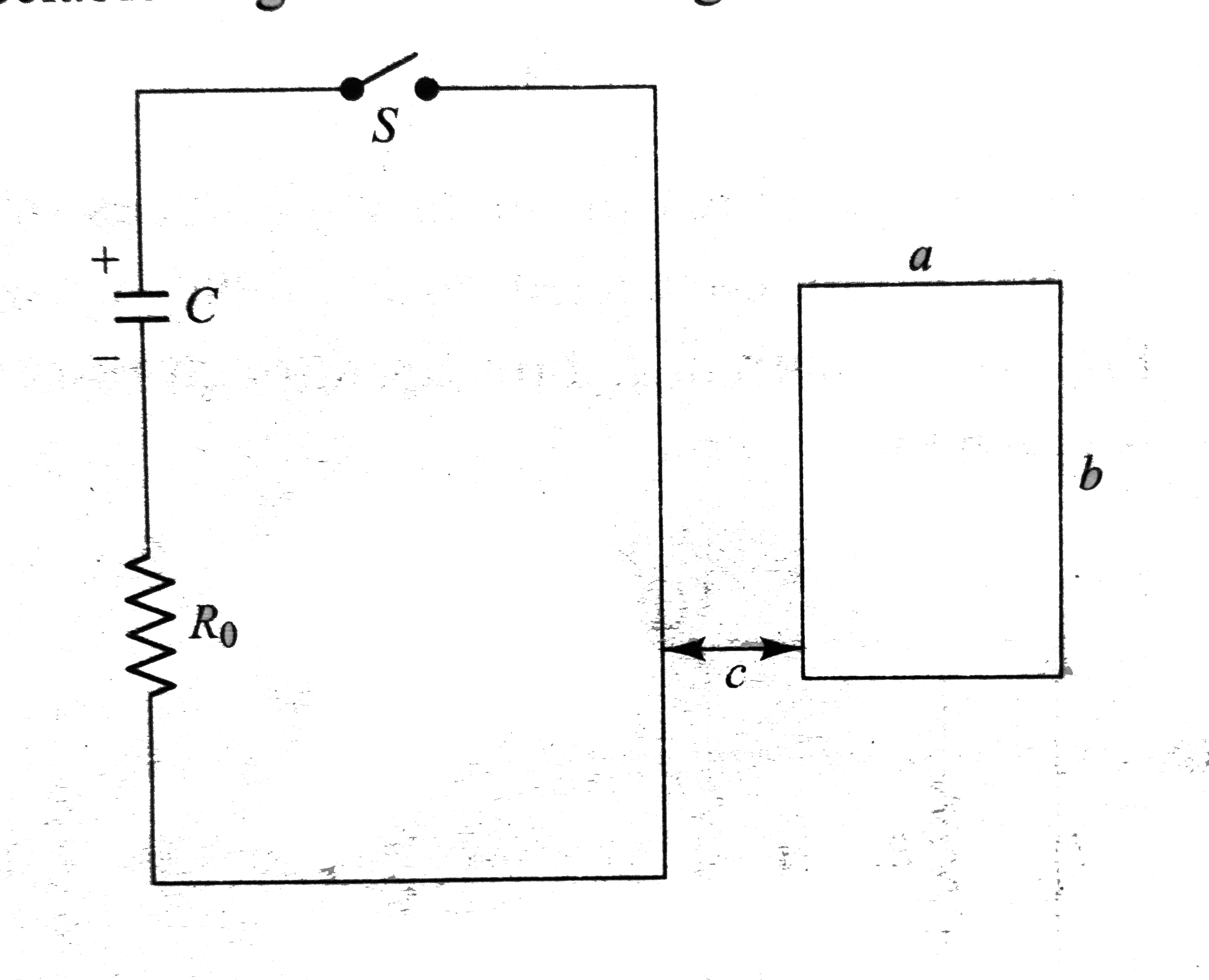
The direction of current in the smaller circuit isView SolutionTwo long parallel conducting rails are placed in a uniform magnetic field. On one side, the rails are connected with a resistance `R`. Two rods `MN and M'N'` each having resistance `r` are placed as showing in Fig. Now on the rods `MN and M'N'` forces are applied such that the rods move with constant velocity `v`.
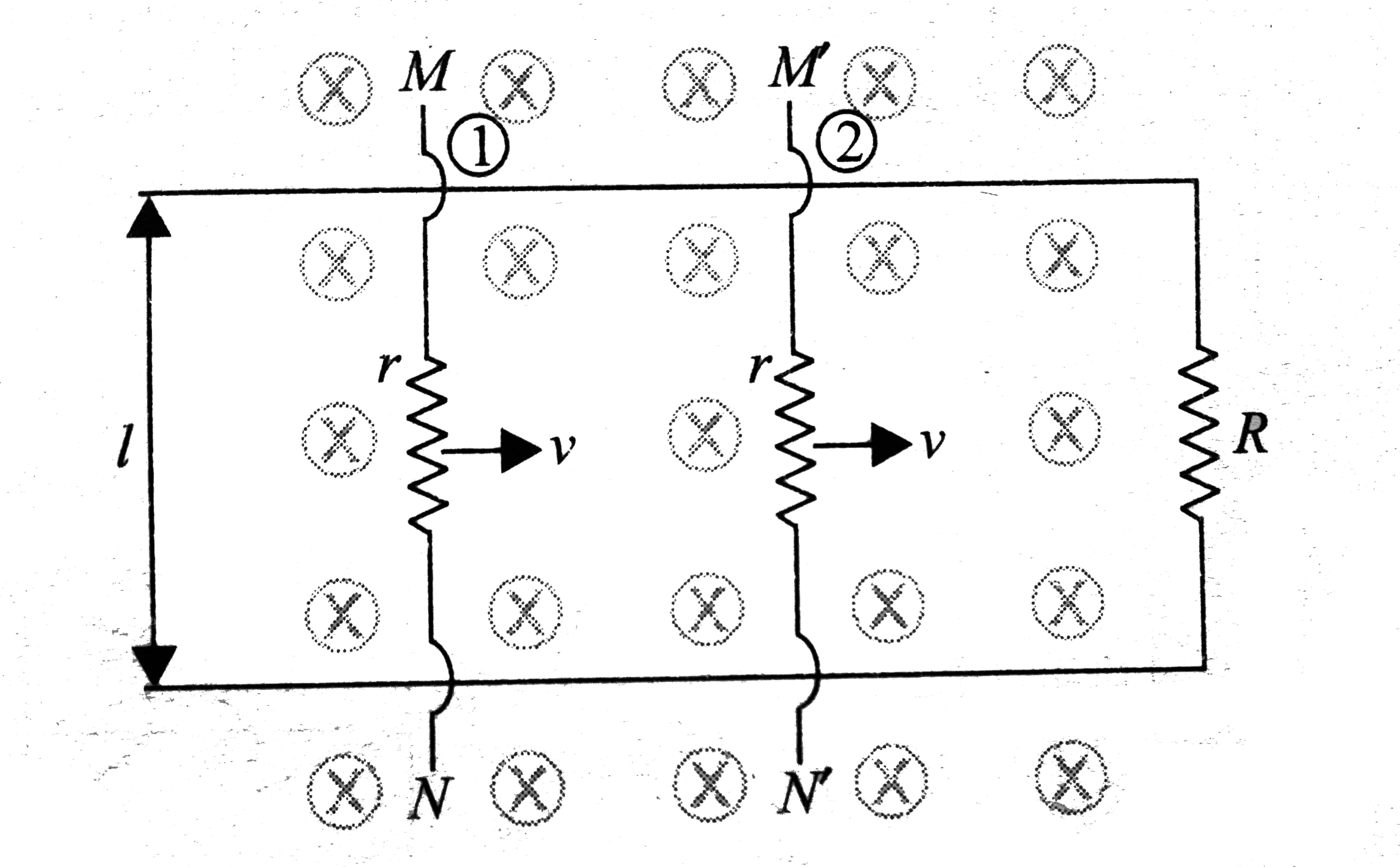
The current flowing through resustance `R` if both the rods move with the same speed `v` toward right is04:37View SolutionTwo long parallel conducting rails are placed in a uniform magnetic field. On one side, the rails are connected with a resistance `R`. Two rods `MN and M'N'` each having resistance `r` are placed as showing in Fig. Now on the rods `MN and M'N'` forces are applied such that the rods move with constant velocity `v`.
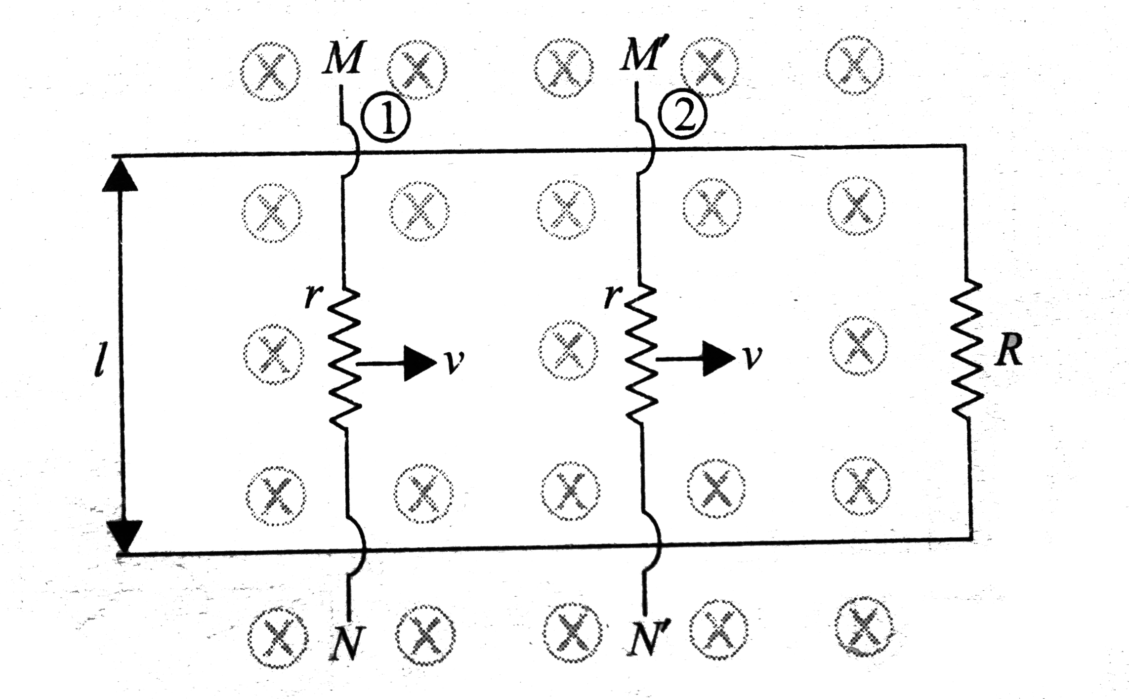
(i). The current flowing through resistance `R` if the rod `Mn` moves toward left and the rod `M'N'` moves toward the right is07:46View SolutionTwo long parallel conducting rails are placed in a uniform magnetic field. On one side, the rails are connected with a resistance `R`. Two rods `MN and M'N'` each having resistance `r` are placed as showing in Fig. Now on the rods `MN and M'N'` forces are applied such that the rods move with constant velocity `v`.
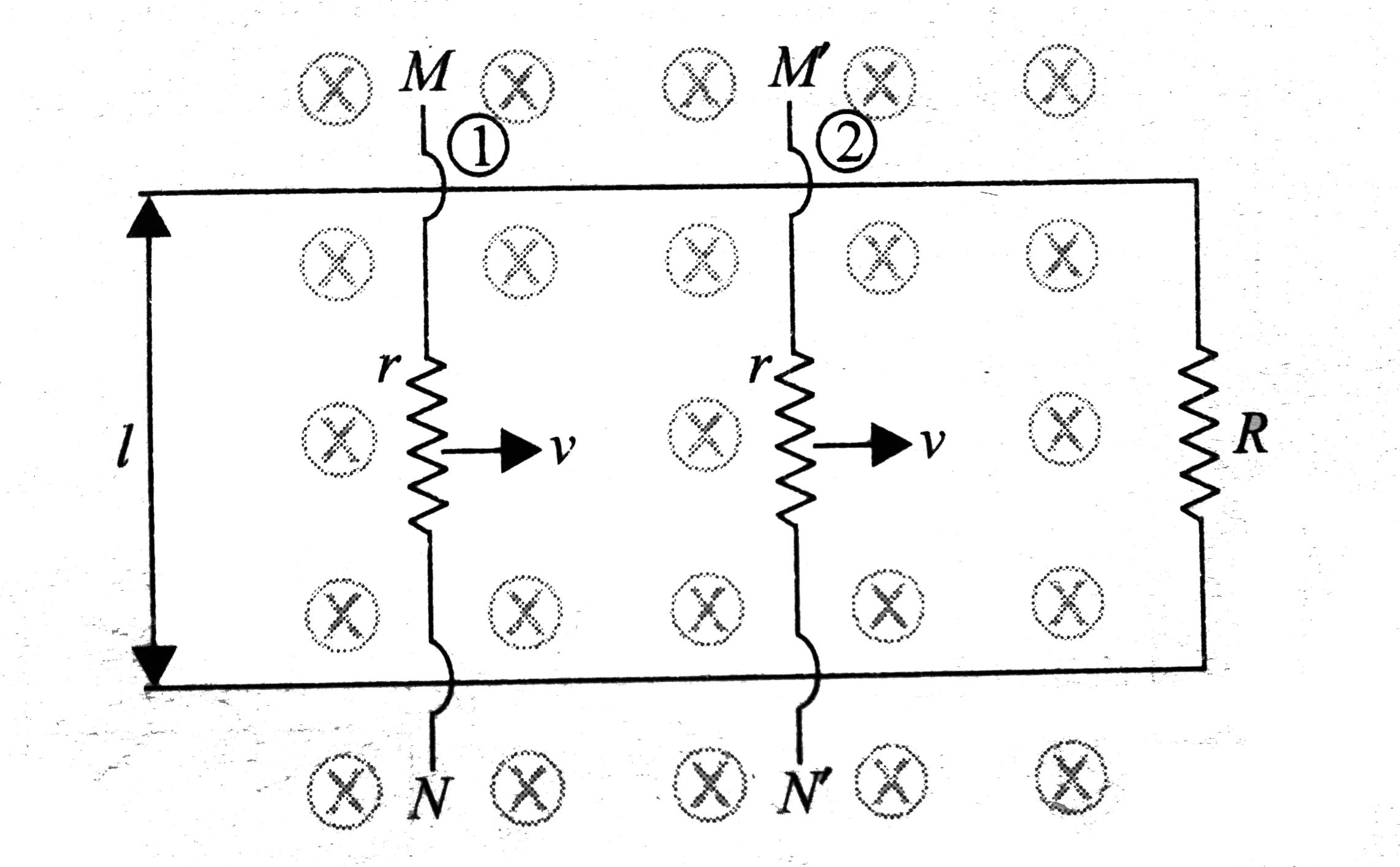
(ii). If in the previous problem resistance of values `R_(1) and R_(2)` are connected on both ends as shown in Fig. current `I`, flowing through resistance `R_(1)` is given byView SolutionA metal bar is moving with a velocity of `v = 5 cm s^(-1)` over a U-shaped conductor. At `t = 0`, the external magnetic field is `0.1 T` direction out of the page and is increasing at a rate of `0.2 T s^(-1)`.
Tale `l = 5cm`, and at `t = 0, x = 5 cm`.
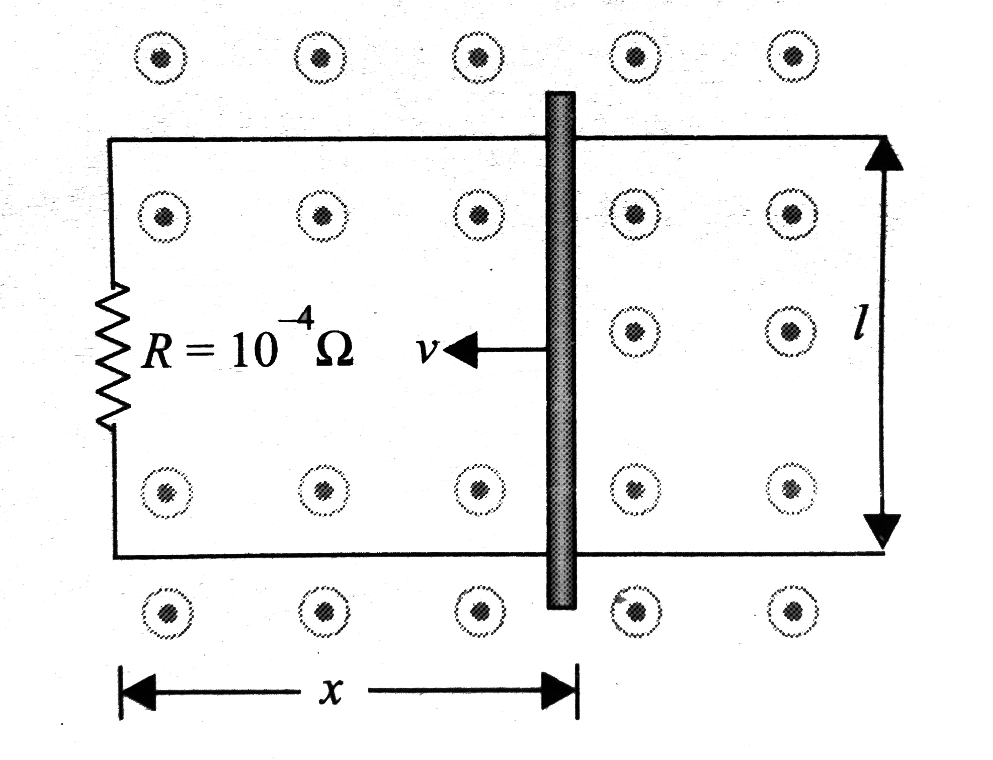
The emf induced in the circuit is03:06View SolutionA metal bar is moving with a velocity of `v = 5 cm s^(-1)` over a U-shaped conductor. At `t = 0`, the external magnetic field is `0.1 T` direction out of the page and is increasing at a rate of `0.2 T s^(-1)`.
Tale `l = 5cm`, and at `t = 0, x = 5 cm`.
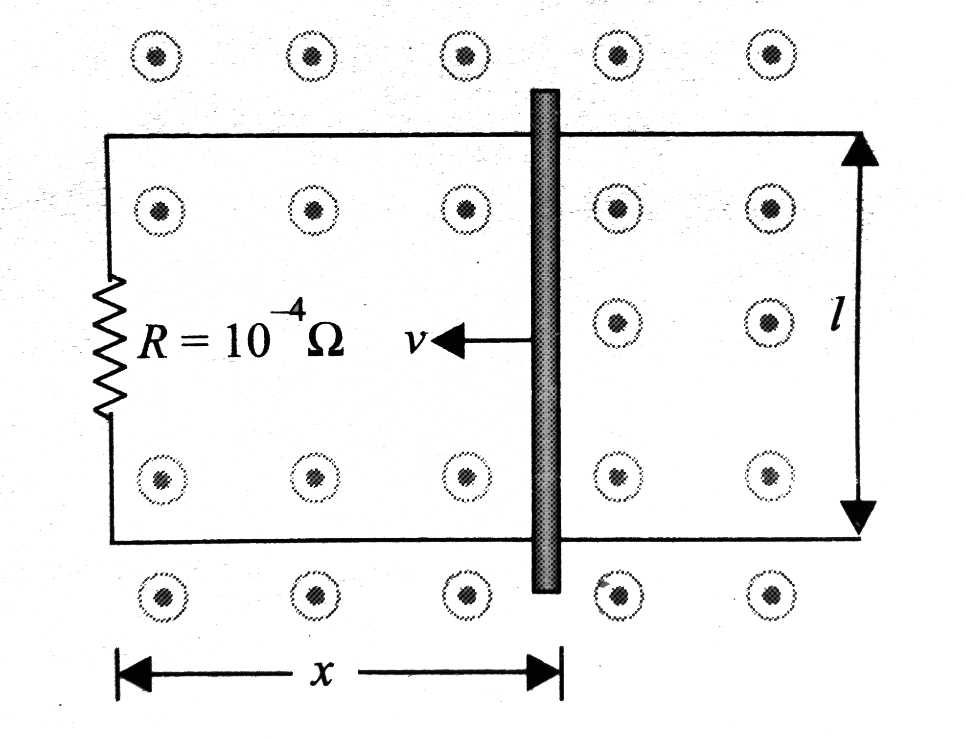
The current flowing in the circuit is02:36View SolutionIn Fig. shown, the rod has a resistance `R`, the horizontal rails have negligible friction. A battery of emf `E` and negligible internal resistance is connected between points `a and b`. The rod is released from rest.
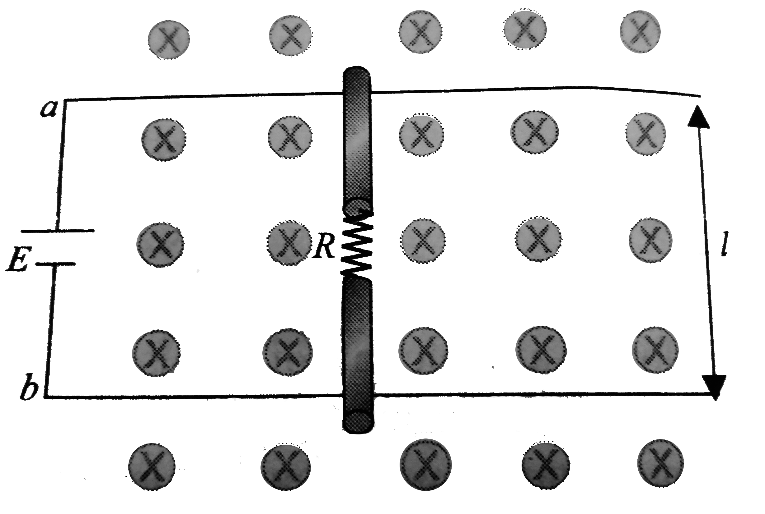
The velocity of the rod as function of time is04:59View SolutionIn Fig. shown, the rod has a resistance `R`, the horizontal rails have negligible friction. A battery of emf `E` and negligible internal resistance is connected between points `a and b`. The rod is released from rest.
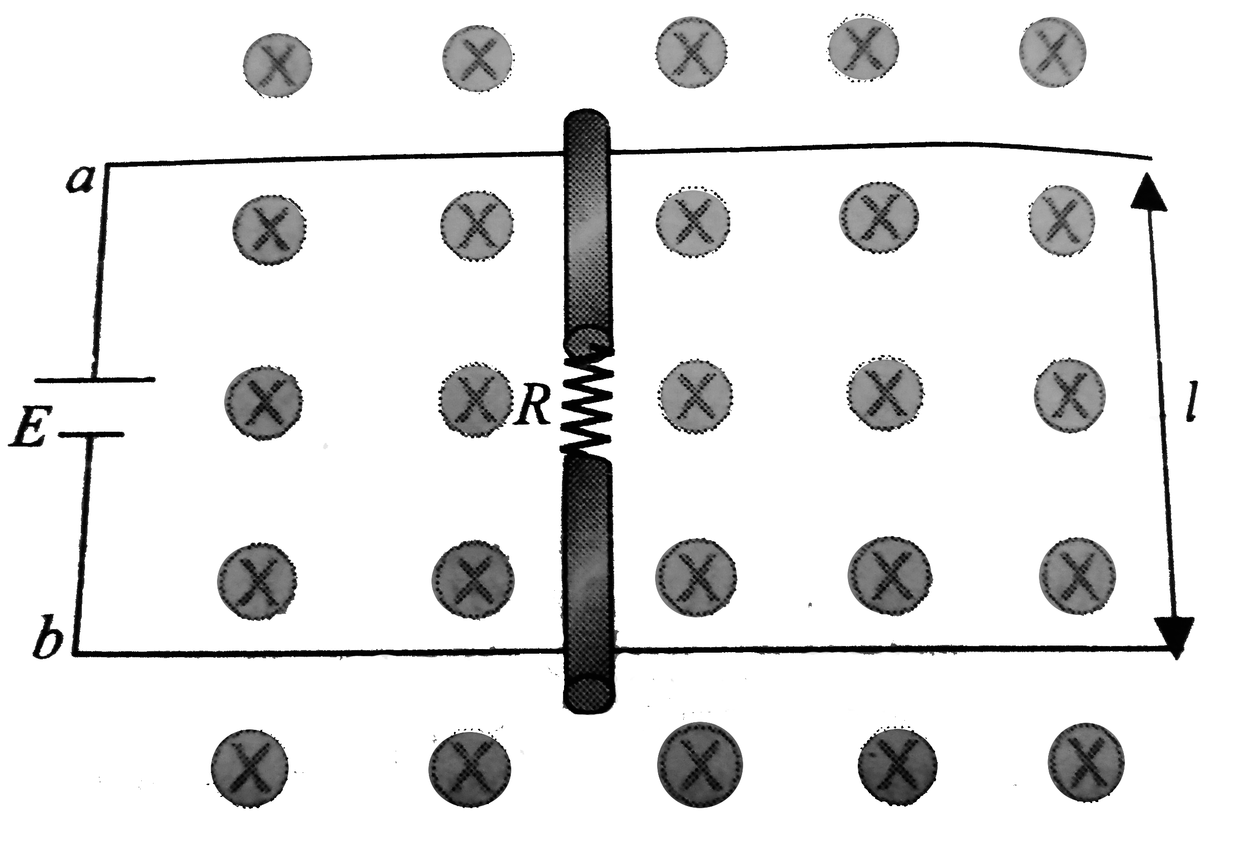
after some time, the rod will approach a terminal speed . Find an expression for it.05:27View SolutionIn Fig. shown, the rod has a resistance `R`, the horizontal rails have negligible friction. A battery of emf `E` and negligible internal resistance is connected between points `a and b`. The rod is released from rest.
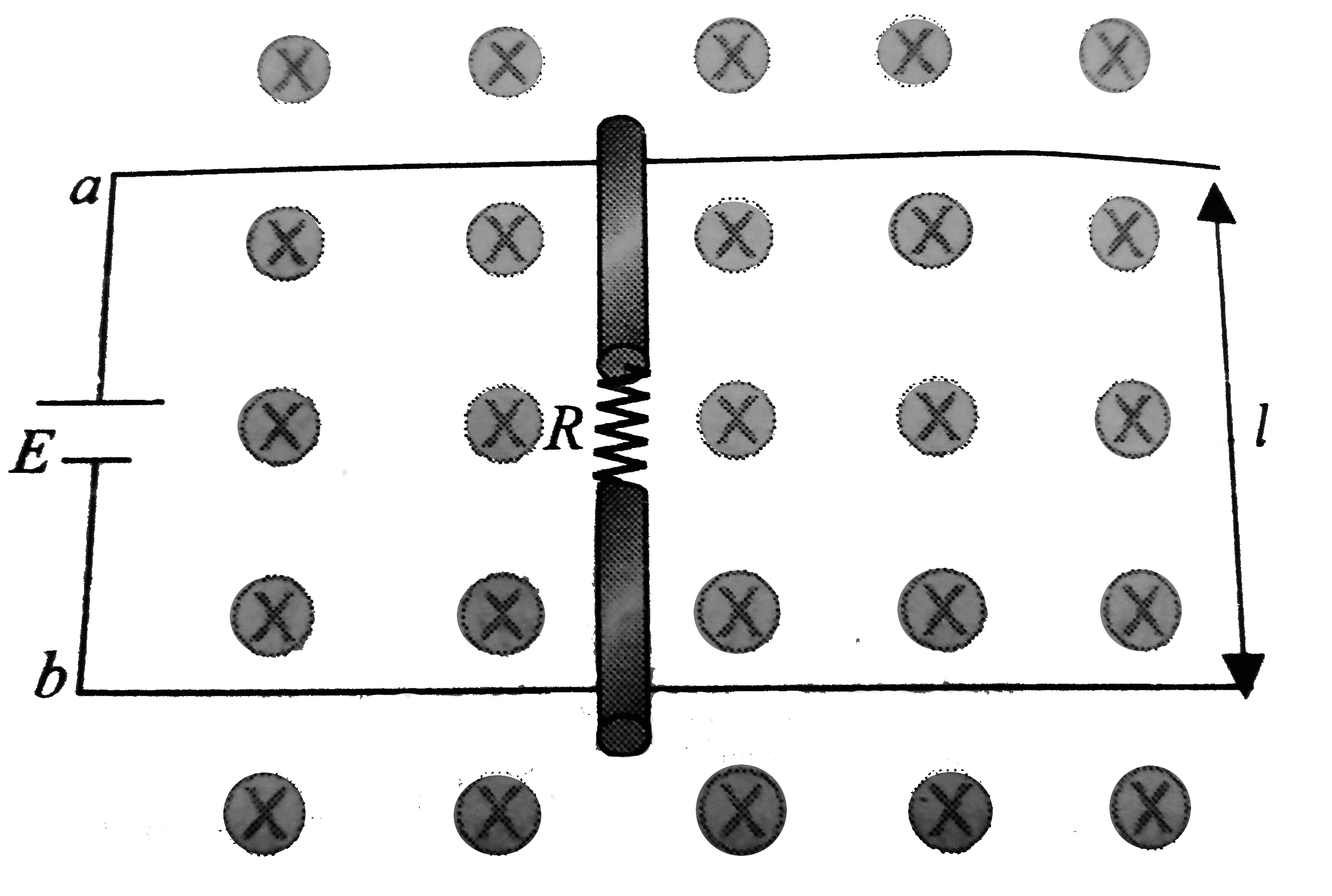
The current when the rod attains its terminal speed is04:55View SolutionA square conductind loop, `20.0 cm` on a side placed in the same magnetic field as shown in Fig. 3.195, center of the magnetic field region, where `dB//dt = 0.035 T s^(-1)`.
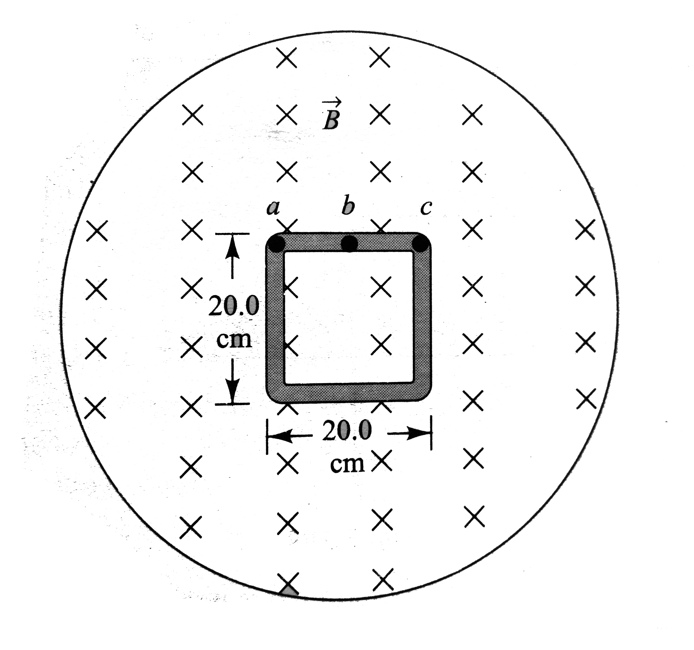
he direction of induced electric field at points a, b and c:03:08View SolutionA square conductind loop, `20.0 cm` on a side placed in the same magnetic field as shown in Fig. 3.195, center of the magnetic field region, where `dB//dt = 0.035 T s^(-1)`.
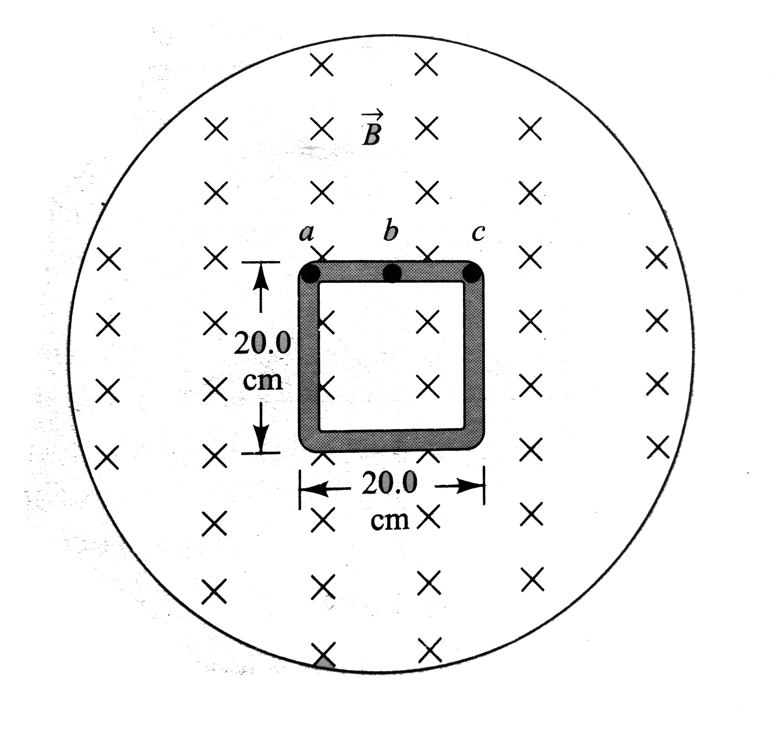
The current induced in the loop if its resistance is `2.00 Omega` is02:48View SolutionA square conductind loop, `20.0 cm` on a side placed in the same magnetic field as shown in Fig. 3.195, center of the magnetic field region, where `dB//dt = 0.035 T s^(-1)`.
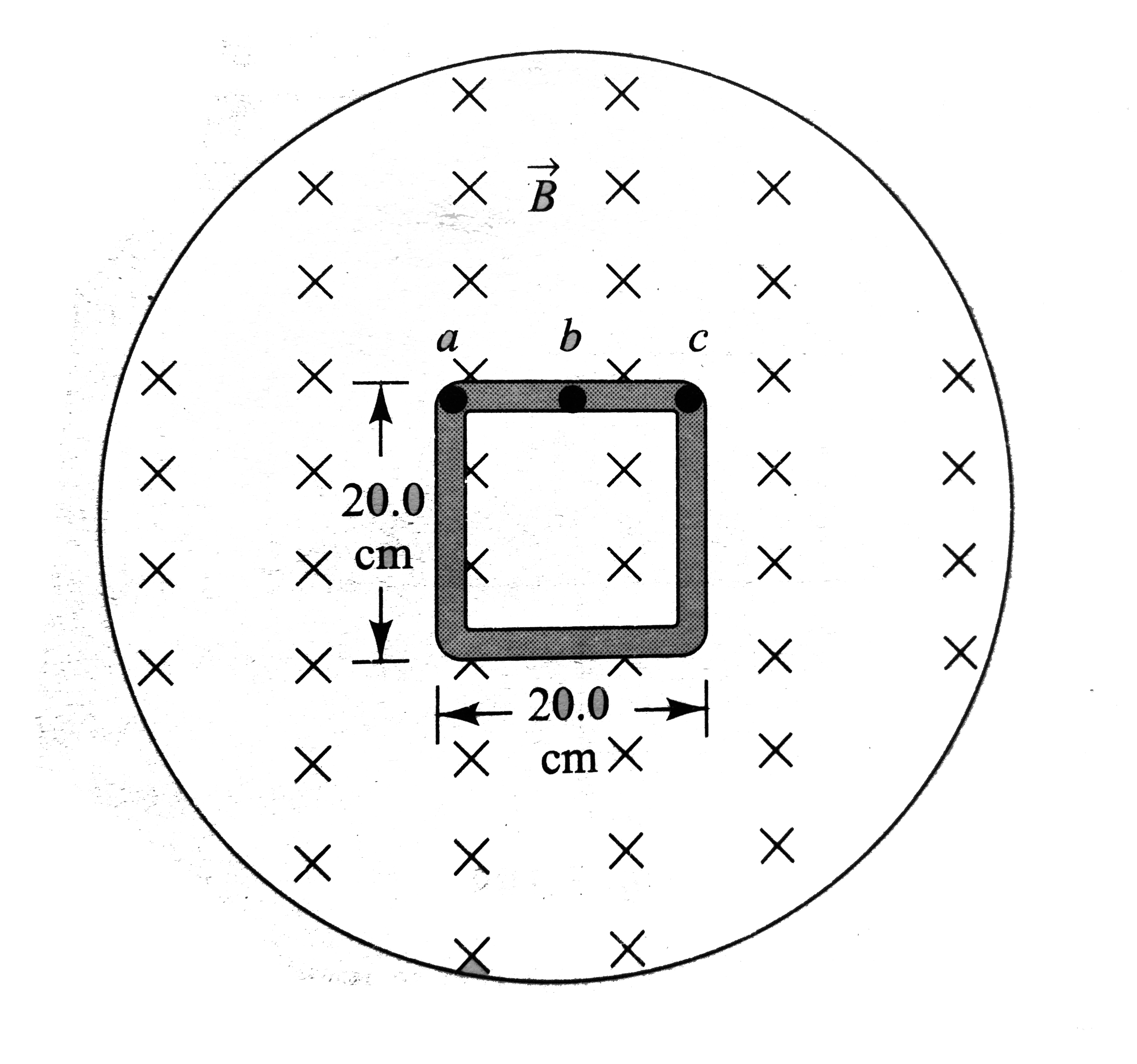
The potential difference between points `a and b` is05:25View SolutionIn a very long solenoid of radius `R`, if the magnetic field chabges at the rate of `dB//dt.AB = BC`
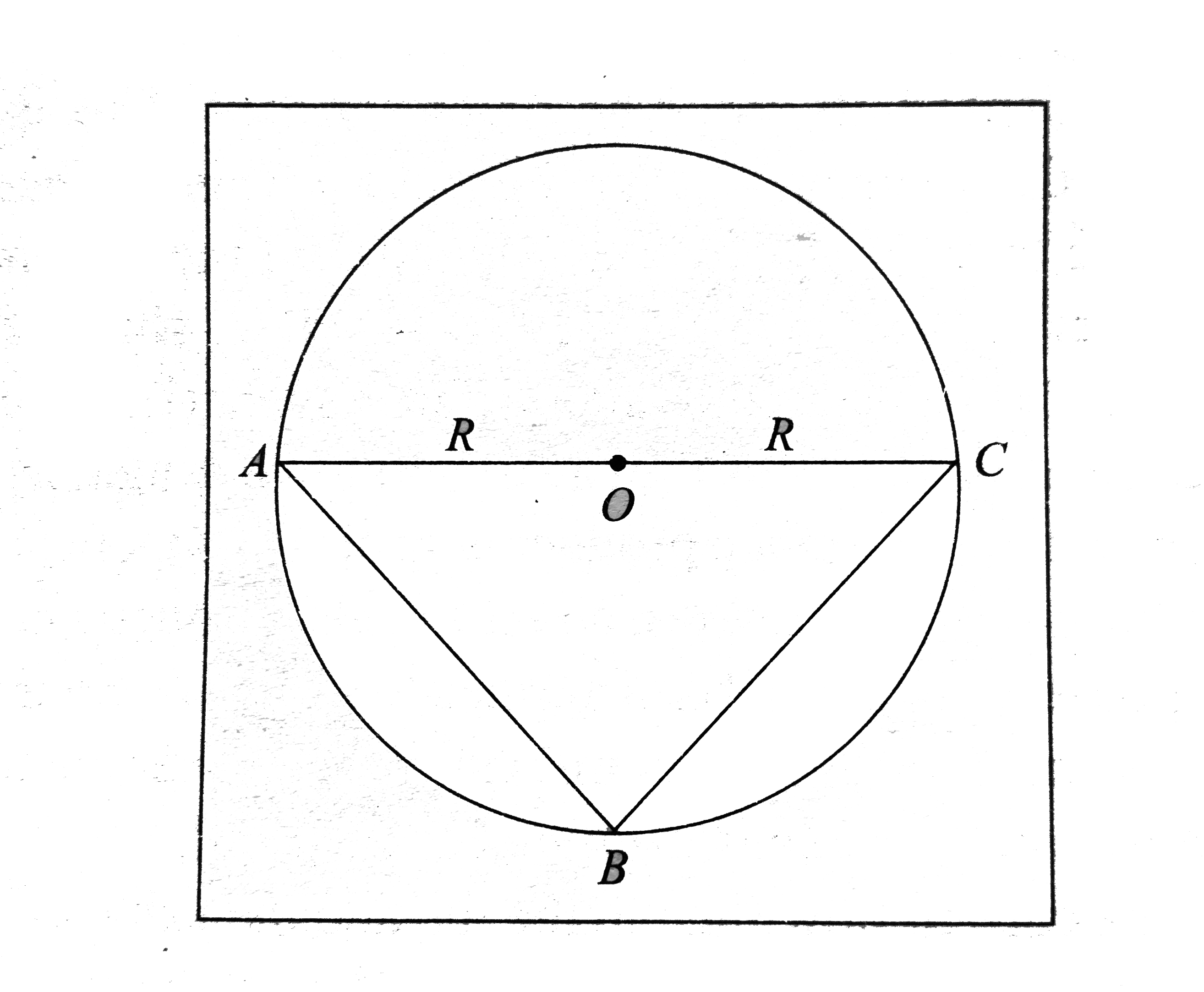
The induced emf for the trianglar circuit `ABC` shown in Fig. 3.196 is
 02:17View Solution
In a very long solenoid of radius `R`, if the magnetic field chabges at the rate of `dB//dt.AB = BC`
The induced emf for the trianglar circuit `ABC` shown in Fig. 3.196 is
 02:17View Solution
A standing wave `y = 2A sin kx cos omegat` is set up in the wire `AB` fixed at both ends by two vertical walls (see Fig. 3.197). The region between the walls contains a constant magnetic field `B`. Now answer the following question:
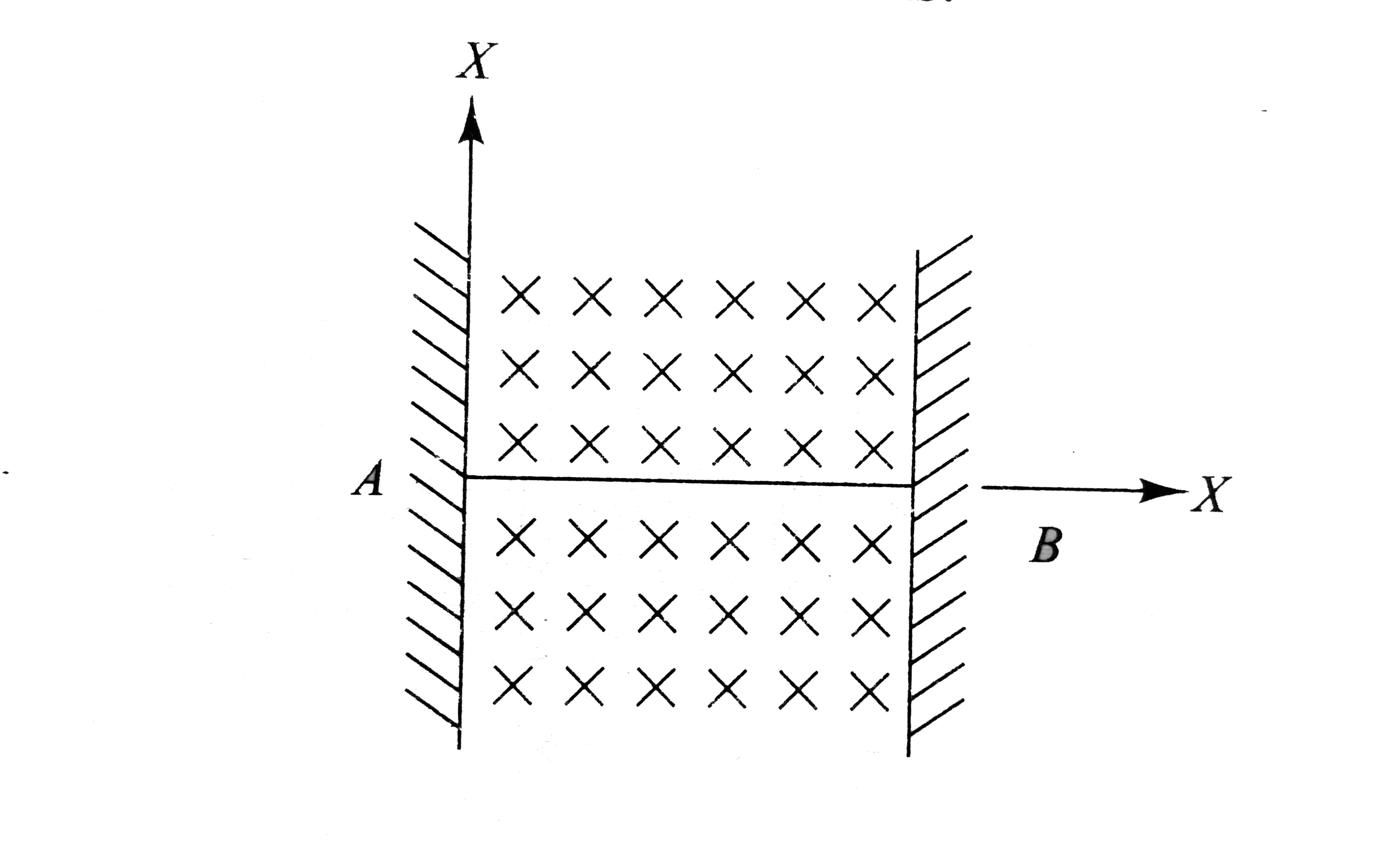
The wire is found to vibrate in the third harmonic. The maximum emf induced is04:25View SolutionA stsnding wave `y = 2A sin kx cos omegat` is set up in the wire `AB` fixed at both ends by two vertical walls (see Fig. 3.197). The region between the walls contains a constant magnetic field `B`. Now answer the following question:
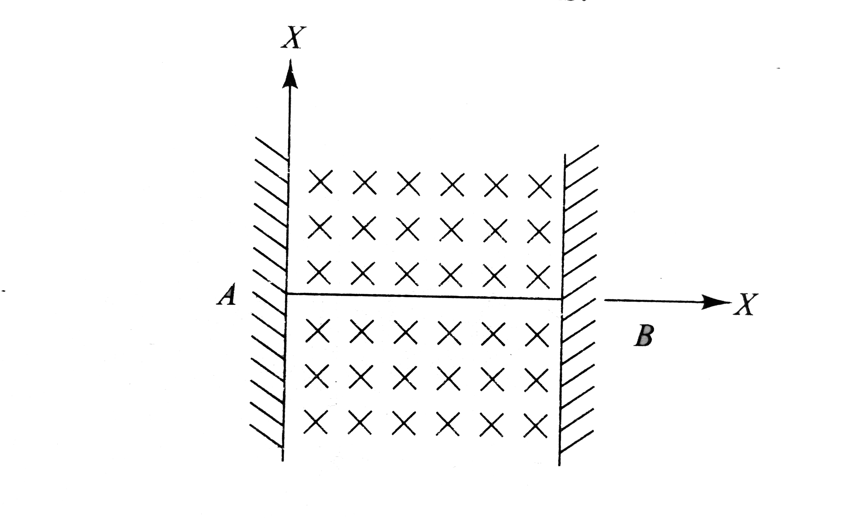
In the above qestion, the time when the emf becomes maximum for the time is05:16View SolutionA stsnding wave `y = 2A sin kx cos omegat` is set up in the wire `AB` fixed at both ends by two vertical walls (see Fig. 3.197). The region between the walls contains a constant magnetic field `B`. Now answer the following question:
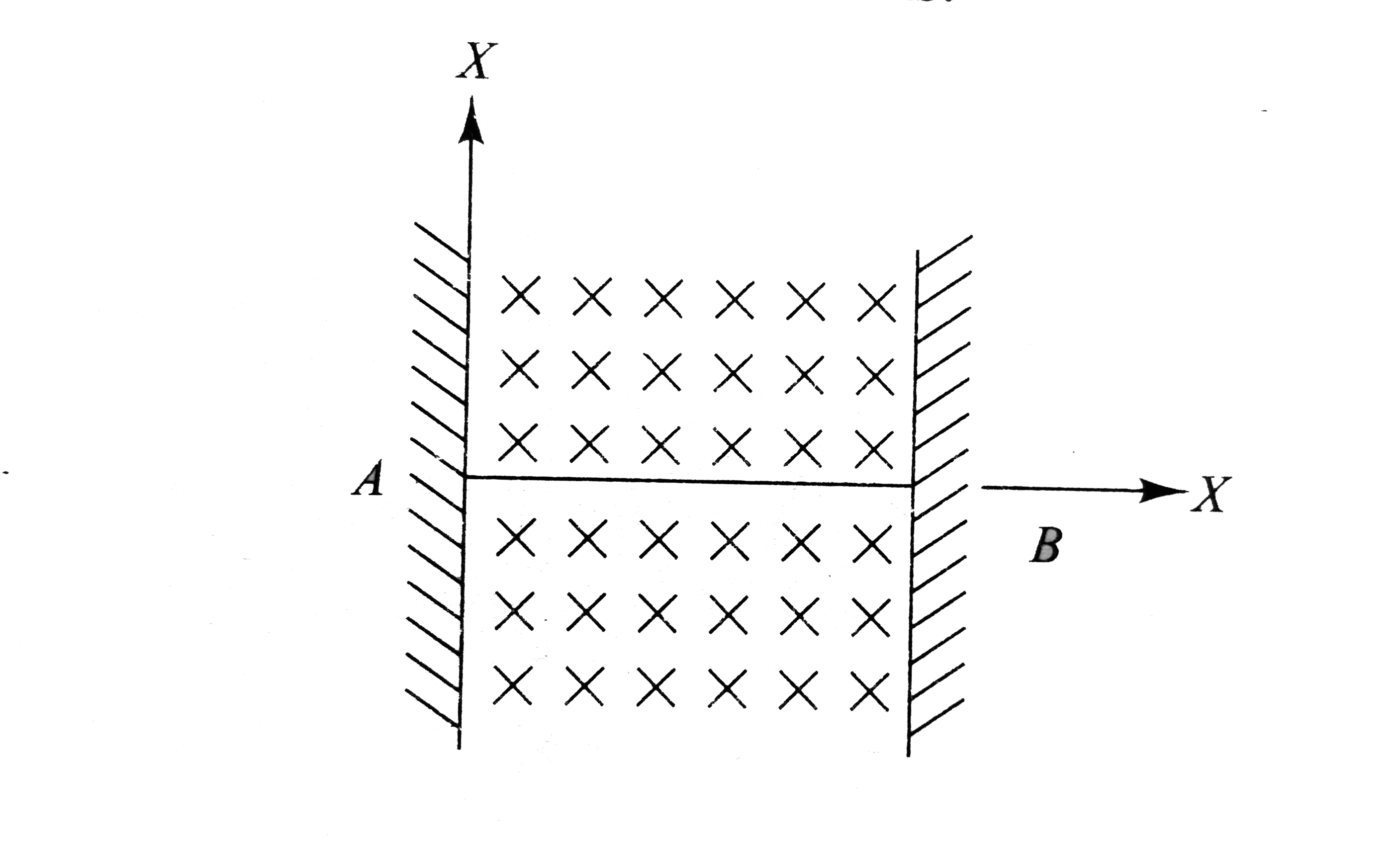
In which of the following modes the emf induced in `AB` is always zero?06:48View SolutionA fan operates at 200 volt `(DC)` consuming `1000W` when running at full speed . It's internal wiring has resistance `1 Omega` . When the fan runs at full speed , its speed becomes constant. This is because the torque due to magnetic field inside tha fan is balanced by the torque due to air resistance on the blades of the fan and torque due to friction between the fixed part and the shaft of the fan. The electrical power going into the fan is spent `(i)` in the internal resistance as heat, call it `P_(1)(ii)` in doing work against internal friction and air resistance producing heat, sound etc. call it `P_(2)`. When the coil of fan rotates, an emf is also induced in the coil. This opposes the external emf applied to snd the current into the fan. This emf is called back-emf,call it `'e'`.
Answer the following questions when the fan is running at full speed.
The current flowing into the fan and the value of back emf e is06:19View SolutionA fan operates at 200 volt `(DC)` consuming `1000W` when running at full speed . It's internal wiring has resistance `1 Omega` . When the fan runs at full speed , its speed becomes constant. This is because the torque due to magnetic field inside tha fan is balanced by the torque due to air resistance on the blades of the fan and torque due to friction between the fixed part and the shaft of the fan. The electrical power going into the fan is spent `(i)` in the internal resistance as heat, call it `P_(1)(ii)` in doing work against internal friction and air resistance producing heat, sound etc. call it `P_(2)`. When the coil of fan rotates, an emf is also induced in the coil. This opposes the external emf applied to snd the current into the fan. This emf is called back-emf,call it `'e'`.
Answer the following questions when the fan is running at full speed.
The value of power `P_(1)` is03:33View SolutionA fan operates at 200 volt `(DC)` consuming `1000W` when running at full speed . It's internal wiring has resistance `1 Omega` . When the fan runs at full speed , its speed becomes constant. This is because the torque due to magnetic field inside tha fan is balanced by the torque due to air resistance on the blades of the fan and torque due to friction between the fixed part and the shaft of the fan. The electrical power going into the fan is spent `(i)` in the internal resistance as heat, call it `P_(1)(ii)` in doing work against internal friction and air resistance producing heat, sound etc. call it `P_(2)`. When the coil of fan rotates, an emf is also induced in the coil. This opposes the external emf applied to snd the current into the fan. This emf is called back-emf,call it `'e'`.
Answer the following questions when the fan is running at full speed.
The value of power `P_(2)` si04:23View SolutionFigure shows a conducting rod of negligible resistance that can slide on smooth U-shaped rail made of wire of resistance `1Omega//m`. Position of the conducting rod at `t=0` is shown. A time dependent magnetic field `B=2t` tesla is switched on at `t=0`
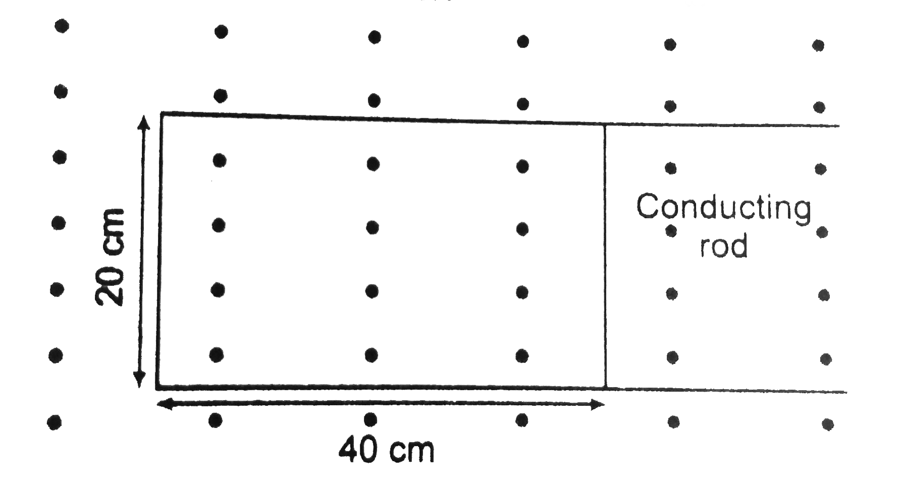
The current in the loop at `t=0` due to induced emf is07:22View SolutionFigure shows a conducting rod of negligible resistance that can slide on smooth U-shaped rail made of wire of resistance `1Omega//m`. Position of the conducting rod at `t=0` is shown. A time dependent magnetic field `B=2t` tesla is switched on at `t=0`
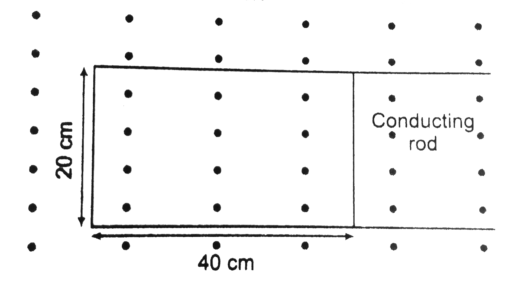
At `t=0`, when the magnetic field is switched on, the conducting rod is moved to the left at constant speed `5cm//s` by some external means. At `t=2s`, net induced emf has magnitude07:22View SolutionFigure shows a conducting rod of negligible resistance that can slide on smooth U-shaped rail made of wire of resistance `1Omega//m`. Position of the conducting rod at `t=0` is shown. A time dependent magnetic field `B=2t` tesla is switched on at `t=0`
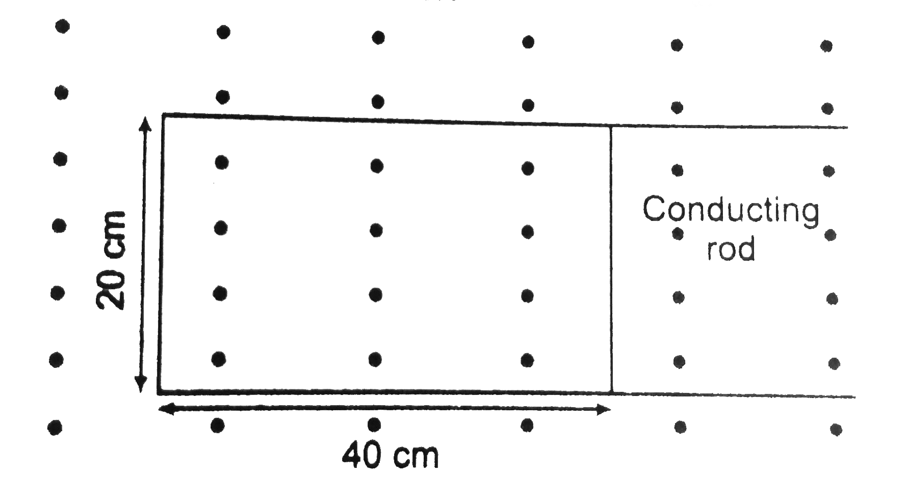 The magnitude of the force required to move the conducting rod at constant speed 5cm/s at the same instant `t=2s`, is equal to07:22View Solution
A brilliant student of physics developed a magnetic balance to weight objects. The mass `m` to be measured is hung from the center the bar. Bar is kept in a uniform magnetic field of `1.5 T` directed into the plane of the figure. Battery voltage can be adjusted to vary the current in the circuit. The horizontal bar shown is `60cm` long and is made of extremly light weight material. It is connected to the battery via a resistance. There is no tension in the supporting wired. The magnetic force only supports the hanging weight.
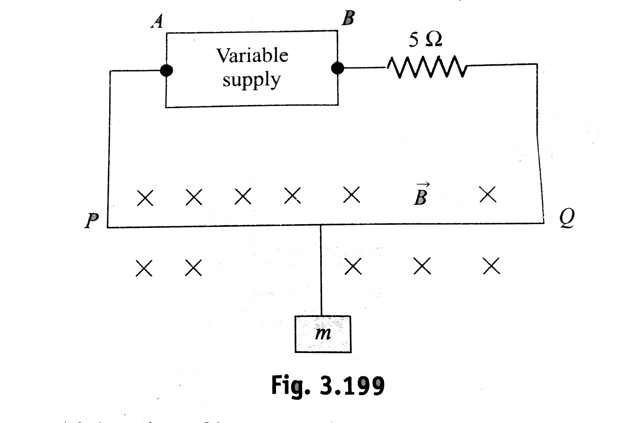
Which point of battery is positive?03:29View SolutionA brilliant student of physics developed a magnetic balance to weight objects. The mass `m` to be measured is hung from the center the bar. Bar is kept in a uniform magnetic field of `1.5 T` directed into the plane of the figure. Battery voltage can be adjusted to vary the current in the circuit. The horizontal bar shown is `60cm` long and is made of extremly light weight material. It is connected to the battery via a resistance. There is no tension in the supporting wired. The magnetic force only supports the hanging weight.
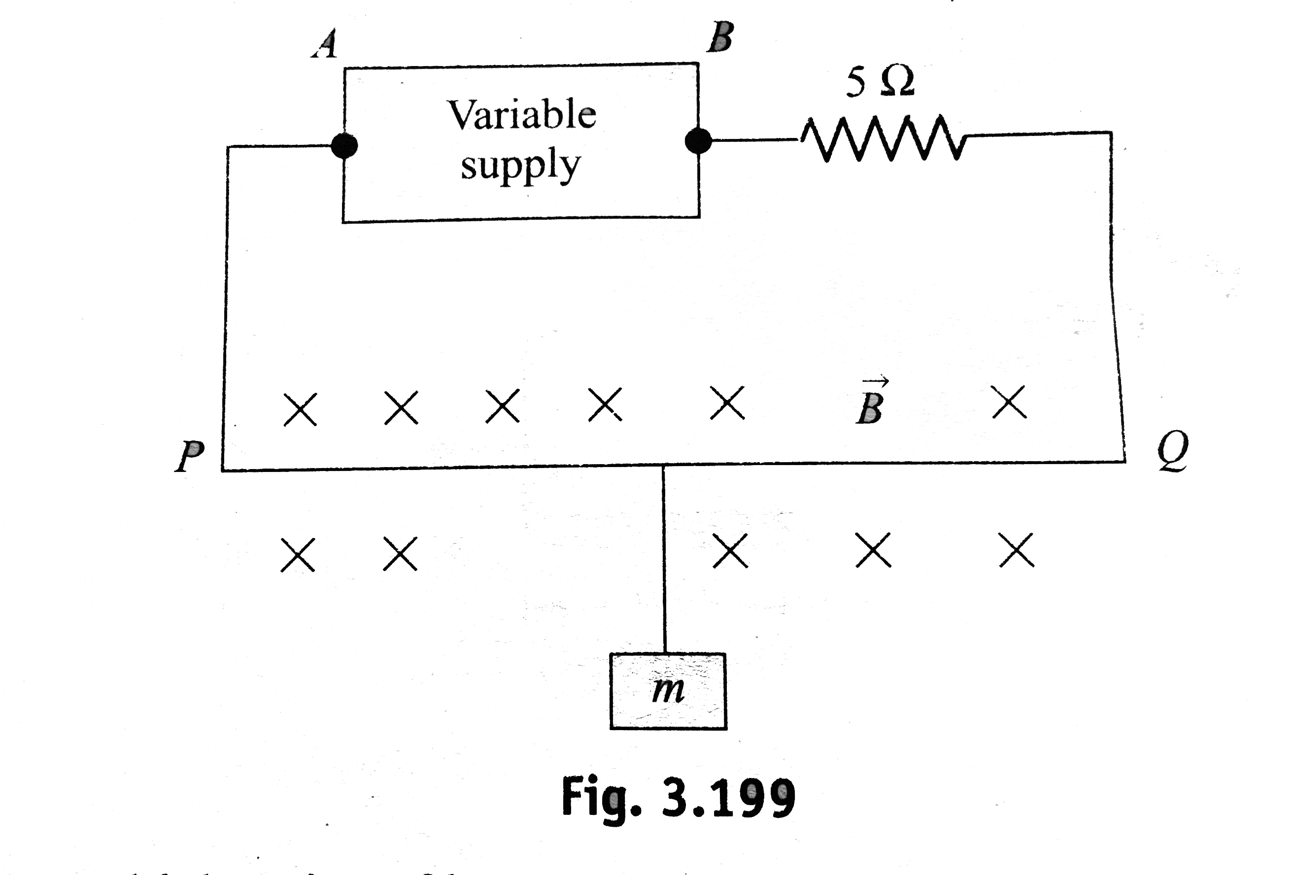
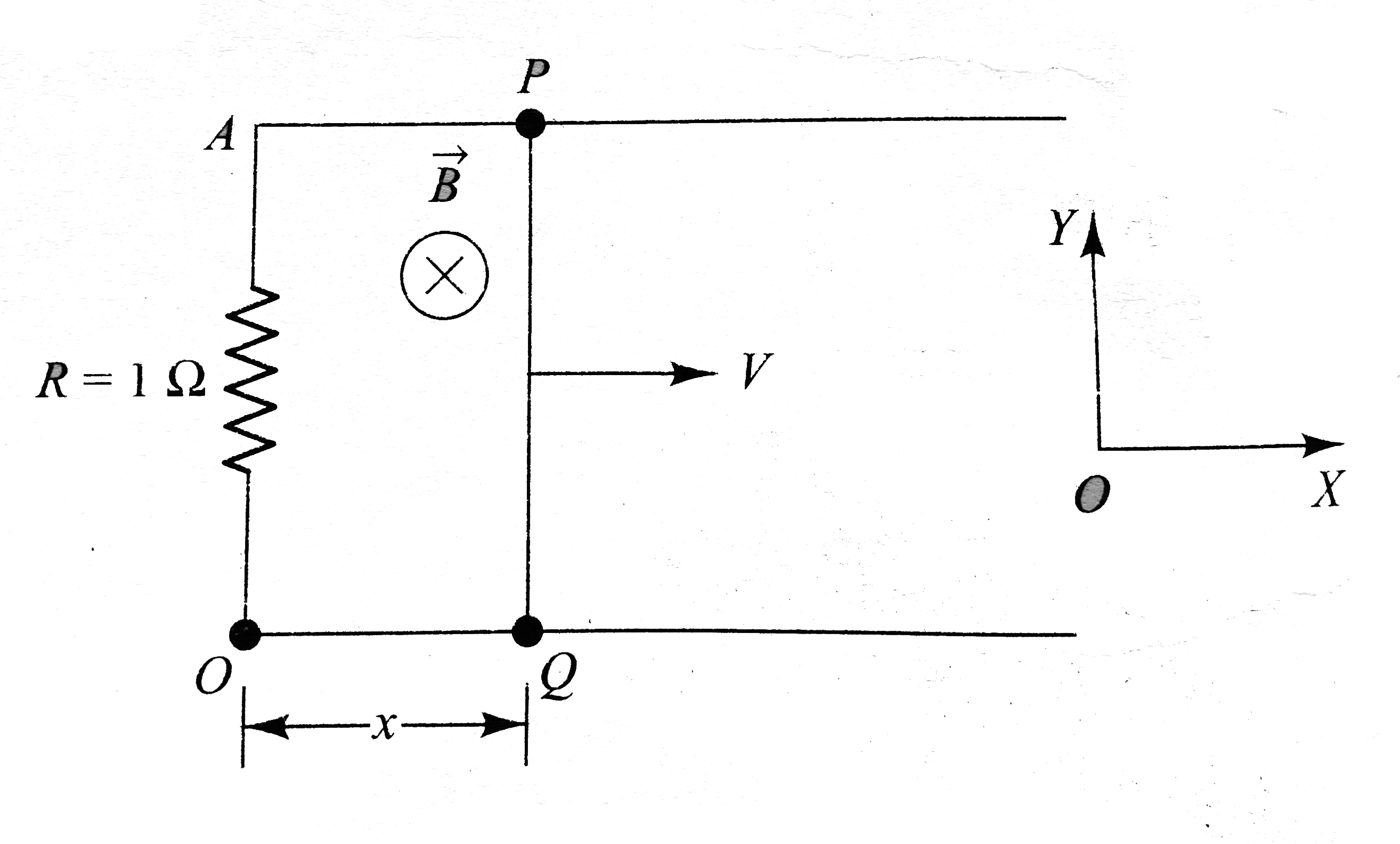
If `V = 150 V`, what is the maximum mass `m` ?04:06View SolutionConsider two parallel conducting frictionless tracks kept in a gravity-free space as shown in Fig. 3.200. A movable conducting `PQ`, initially kept at `OA`, is given a velocity `10 ms^(-1)` toward right. The space contains a magnetic field which depends upon the distance moved by conductor `PQ` from the `OA` line and given by
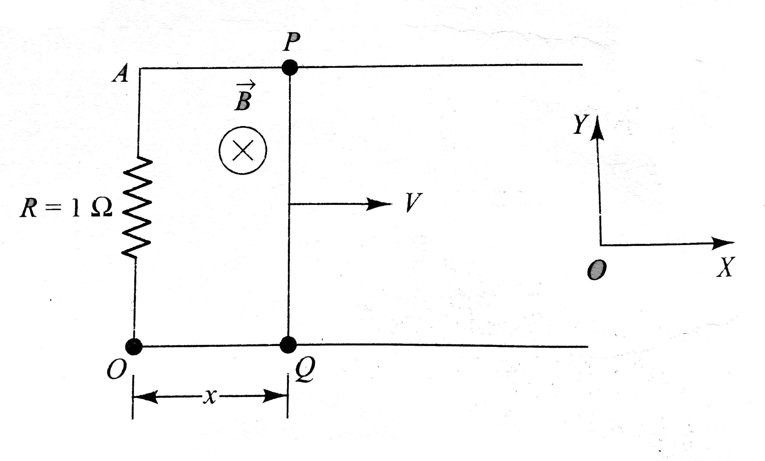
`vec(B) = cx(-hat(k)) [c = constant = 1 SI unit]`
The mass of the conductor `PQ` is `1 kg` and length of `PQ` is 1m. Answer the following question based on the passage.
The distance travelled by the conductor when its speed is `5 ms^(-1)` is08:49View SolutionConsider two parallel conducting frictionless tracks kept in a gravity-free space as shown in Fig. 3.200. A movable conducting `PQ`, initially kept at `OA`, is given a velocity `10 ms^(-1)` toward right. The space contains a magnetic field which depends upon the distance moved by conductor `PQ` from the `OA` line and given by
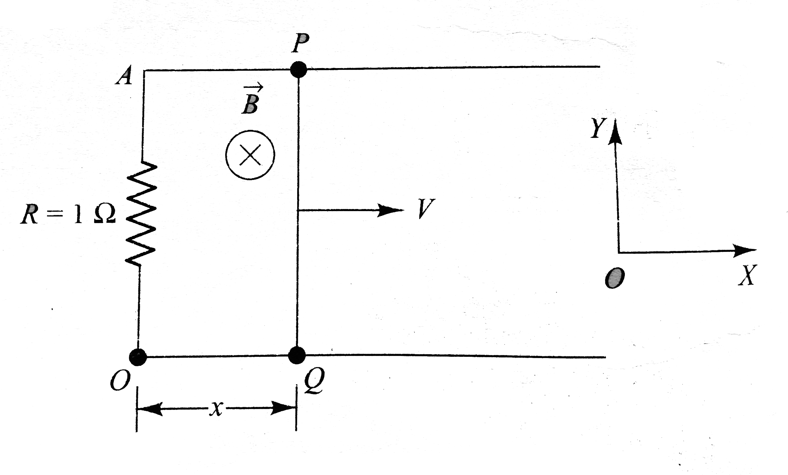
`vec(B) = cx(-hat(k)) [c = constant = 1 SI unit]`
The mass of the conductor `PQ` is `1 kg` and length of `PQ` is 1m. Answer the following question based on the passage.
The loss during the time interval `t = 0` to time `t` seconds when the speed of the conductor is `5 ms^(-1)` is02:51View SolutionConsider two parallel conducting frictionless tracks kept in a gravity-free space as shown in Fig. 3.200. A movable conducting `PQ`, initially kept at `OA`, is given a velocity `10 ms^(-1)` toward right. The space contains a magnetic field which depends upon the distance moved by conductor `PQ` from the `OA` line and given by
`vec(B) = cx(-hat(k)) [c = constant = 1 SI unit]`
The mass of the conductor `PQ` is `1 kg` and length of `PQ` is 1m. Answer the following question based on the passage.
The work done by magnetic force acting on the conductor `PQ` during its motion in the time interval `t = 0 to t = t` second when the speed of conductor is `5 ms^(-1)` is02:50View Solution
Exercises Linked Comprehension questions and complete solutions for chapter ELECTROMAGNETIC INDUCTION of CENGAGE PHYSICS (HINGLISH) of Class 12
All Exercises from CENGAGE PHYSICS Class 12 PHYSICS ELECTROMAGNETIC INDUCTION
- Archives Asserton - Reasoning
- Archives Fill In The Blanks
- Archives Multiple Correct
- Archives Single Correct
- comprehensive
- comprehensive type
- compression type
- Exercise 3.1
- Exercise 3.2
- Exercises Asserton - Reasoning
- Exercises Integer
- Exercises Linked Comprehension
- Exercises Multiple Correct
- Exercises Single Correct
- Exercises Subjective
- Illustration
- Multiple correct Answer Type
- single correct
- single correct
- single correct answer
- Single Correct Answer Type
- Solved Example
