A series LCR circuit driven by 300V at a frequency of 50 Hz contains a resistance R=3kΩ an inductor of inductive reactance XL=250πΩ and an unknown capacitor. The value of capacitance to maximize the average power should be (Take π2=10 )
400μF
4μF
40μF
25μF
The correct Answer is:B
To find the value of capacitance that maximizes the average power in a series LCR circuit, we need to follow these steps:
Step 1: Understand Resonance Condition
In a series LCR circuit, the average power is maximized at resonance. At resonance, the inductive reactance XL is equal to the capacitive reactance XC.
Step 2: Write the Expression for Reactances
The inductive reactance is given as:
XL=250πΩ
The capacitive reactance is given by:
XC=1ωC
where ω=2πf and f is the frequency.
Step 3: Calculate ω
Given that the frequency f=50Hz:
ω=2πf=2π×50=100πrad/s
Step 4: Set XL Equal to XC
At resonance, set XL=XC:
250π=1ωC
Substituting ω:
250π=1100πC
Step 5: Solve for Capacitance C
Rearranging the equation to solve for C:
C=1250π×100π
C=125000π2
Step 6: Substitute π2
Given that π2=10:
C=125000×10=1250000
Step 7: Calculate the Final Value of C
Calculating C:
C=4×10⁻⁶F=4μF
Final Answer
The value of capacitance to maximize the average power is:
C=4μF
---
In a series LCR circuit, the average power is maximized at resonance. At resonance, the inductive reactance XL is equal to the capacitive reactance XC.
The inductive reactance is given as:
XL=250πΩ
The capacitive reactance is given by:
XC=1ωC
where ω=2πf and f is the frequency.
Given that the frequency f=50Hz:
ω=2πf=2π×50=100πrad/s
At resonance, set XL=XC:
250π=1ωC
Substituting ω:
250π=1100πC
Rearranging the equation to solve for C:
C=1250π×100π
C=125000π2
Given that π2=10:
C=125000×10=1250000
Calculating C:
C=4×10⁻⁶F=4μF
The value of capacitance to maximize the average power is:
C=4μF
Similar Questions
A series RLC circuit , driven with Erms=120 V at frequency fd=60.0 Hz, contains a resistance R=200Ω, and inductance with inductive reactance XL=80.0Ω, and a capacitance with capacitive reactance XC=150Ω.
(a) What are the power factor cos ϕ and phase constant ϕ of the circuit ?
View Solution(a) What is the reactance of a 2.00H inductor at a frequency of 50.0Hz?
(b) What is the inductance of an inductor whose reactance is 2.00Ω at 50.0Hz?
(c) What is the reactance of a 2.00μF capacitor at a frequency of 50.0Hz?
(d) What is the capacitance of a capacitor whose reactance is 2.00Ω at 50.0Hz?
View Solution
Knowledge Check
A series LR circuit is connected to an ac source of frequency ω and the inductive reactance is equal to 2R. A capacitance of capacitive reactance equal to R is added in series with L and R. The ratio of the new power factor to the old one is
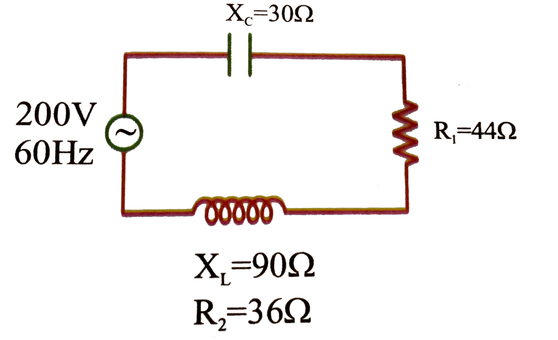
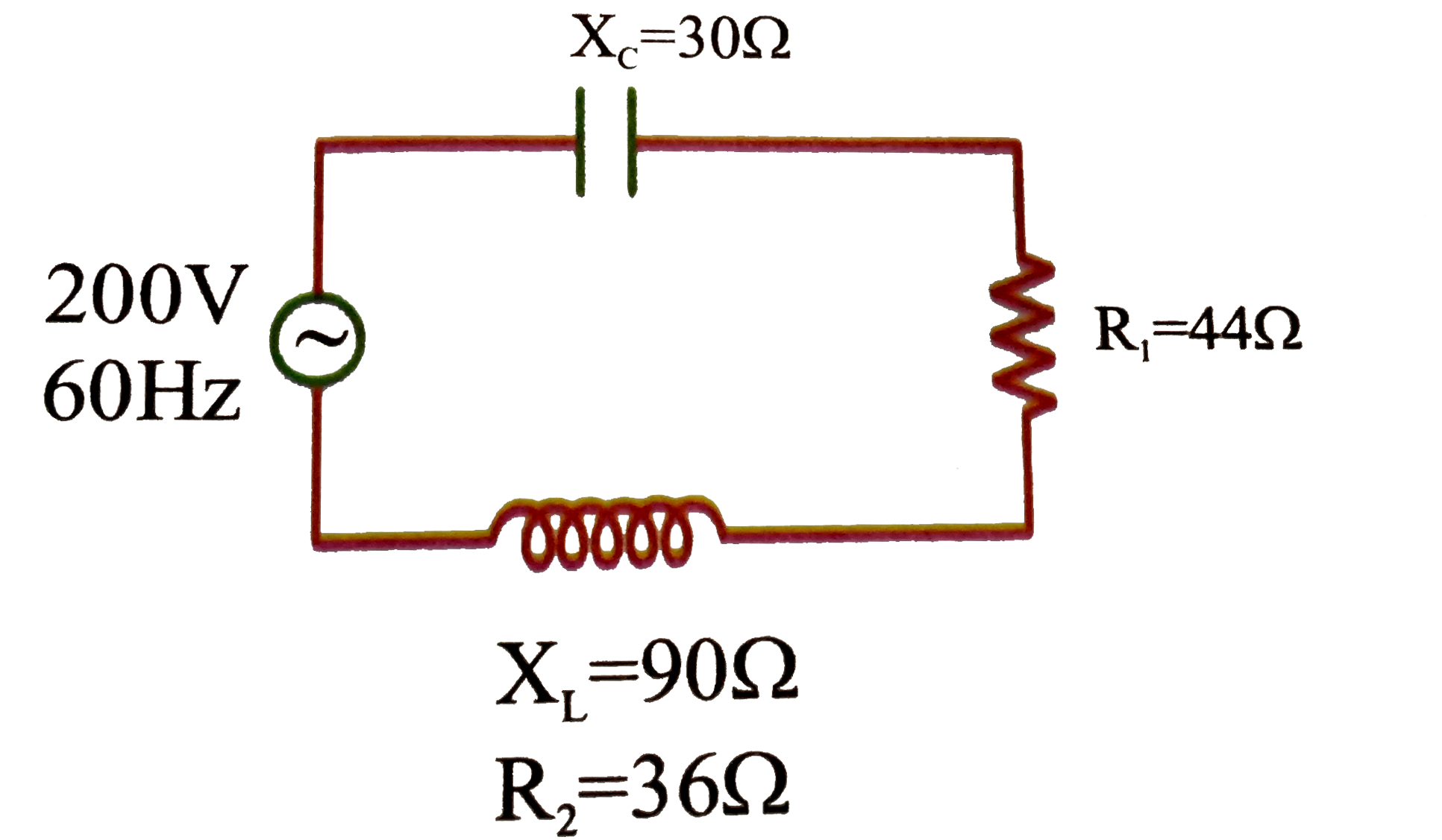
A√23B√25C√32D√52A series circuit connected across a 200V,60Hz line consists of a capacitive reactance 30Ω non inductive resistor of 44Ω and a coil of inductive reactance 90Ω and resistance 36Ω as shown in the diagram

The power used in the circuit isA320WB144WC160WD96WAs given in the figure a series circuit connected across a 200 V, 60 Hz line consists of a capacitor of capacitive reactance 30Ω , a non-inductive resistor 44Ω , a coil of inductive reactance 9012 and another resistance of resistance 36Ω. The power dissipated in the circuit is
 A320 WB176 WC144 WD0 W
In series LCR circuit R=120Ω and it has resonant frequency 4000rad/sec. At resonance, the voltage across resistance and inductance is 60 V and 40 V respectively. Find the value of L and C in circuit.
View SolutionIn a seris LCR circuit, the inductive reactance (XL) is 10Ω and the capacitive reactance (XC) is 4Ω. The resistance (R) in the circuit is 6Ω. The power factor of the circuit is :
View SolutionA series circuit connected across a 200V,60Hz line consists of a capacitive reactance 30Ω non inductive resistor of 44Ω and a coil of inductive reactance 90Ω and resistance 36Ω as shown in the diagram

The power dissipated in the inductance coil is
View SolutionIn LCR series circuit an ac emf of 2 volt and frequency 50 Hz is applied across the combination. If resistance is 4Ω, capacitance is 8μF and inductance is 10−2H then the voltage across inductor will be
View SolutionThe power factor of a circuit containing a lamp of resistance 100 Ω, a choke coil of inductance 0.2 H and a condenser of capacitance 1 mH connected in series with an alternating emf of frequency 50 Hz is
View Solution
