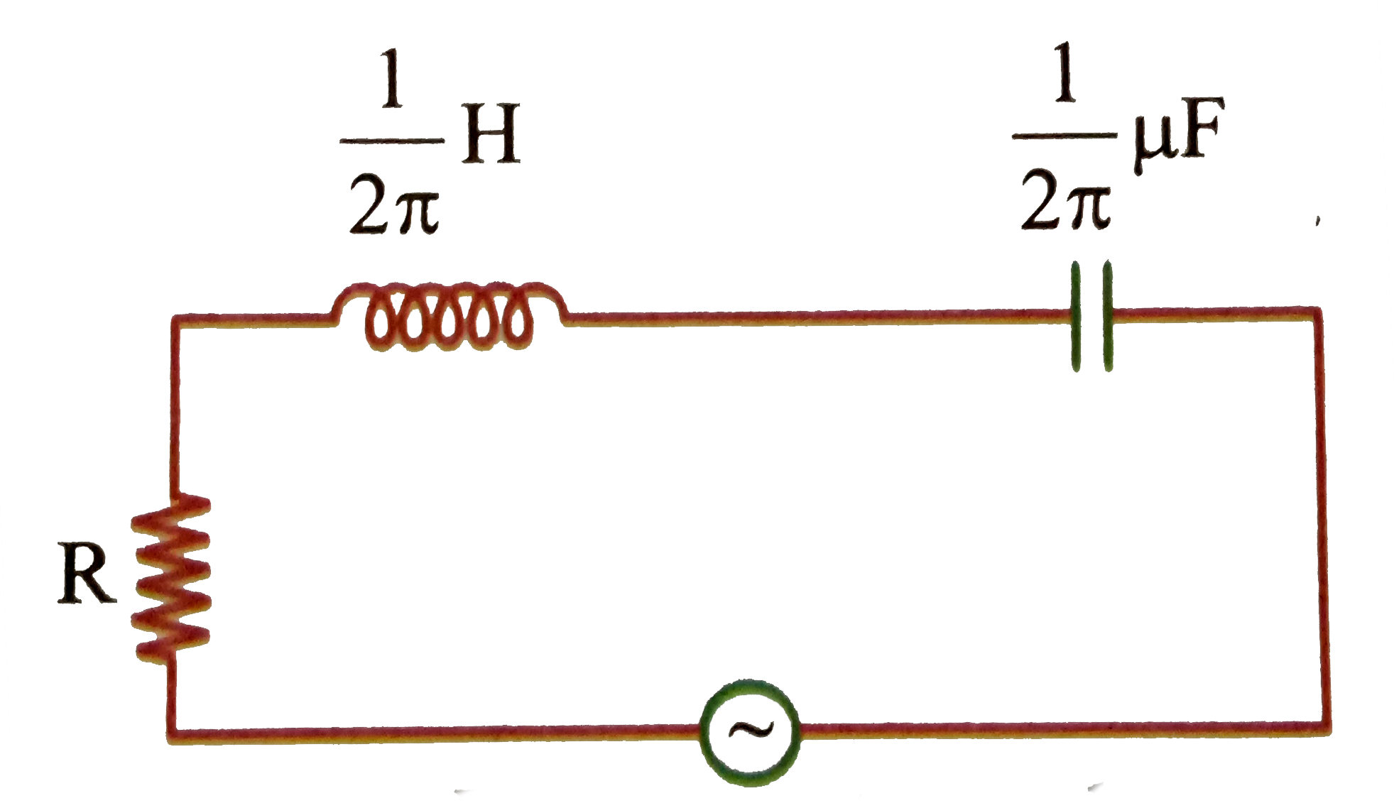
In an LCR series resonant circuit which one of the following cannot be the expression for the Q-factor
(ωr)LR
1ωCR
√LC1R
RLC
The correct Answer is:D
To determine which expression cannot be the Q-factor in an LCR series resonant circuit, we will analyze the Q-factor and its possible expressions step by step.
1. Understanding the Q-factor:
The Q-factor (Quality factor) of a resonant circuit is a dimensionless parameter that describes how underdamped the circuit is, and it is defined as the ratio of the reactive power to the resistive power in the circuit.
2. Basic Formula for Q-factor:
The Q-factor can be expressed in terms of the inductive reactance (XL) and the resistance (R) of the circuit:
Q=XLR
where XL=ωL (with ω being the angular frequency).
3. Resonance Condition:
At resonance in an LCR circuit, the inductive reactance equals the capacitive reactance:
XL=XC⇒ωL=1ωC
This leads to the resonant frequency:
ω0=1√LC
4. Alternative Expressions for Q-factor:
Using the resonance condition, we can express the Q-factor in different forms:
- Substituting XL into the Q-factor formula:
Q=ωLR
- Another form can be derived from the relationship between XC and R:
Q=XCR=1/ωCR=1ωCR
5. Evaluating Given Options:
Now, we will check the possible expressions for the Q-factor:
- Option 1: ωLR - This is valid.
- Option 2: 1ωCR - This is also valid.
- Option 3: 1ωCR - This can be rearranged to show it is valid.
- Option 4: RLC - This does not fit any derived expression for the Q-factor.
6. Conclusion:
The expression that cannot be the Q-factor in an LCR series resonant circuit is:
Option 4: RLC
The Q-factor (Quality factor) of a resonant circuit is a dimensionless parameter that describes how underdamped the circuit is, and it is defined as the ratio of the reactive power to the resistive power in the circuit.
The Q-factor can be expressed in terms of the inductive reactance (XL) and the resistance (R) of the circuit:
Q=XLR
where XL=ωL (with ω being the angular frequency).
At resonance in an LCR circuit, the inductive reactance equals the capacitive reactance:
XL=XC⇒ωL=1ωC
This leads to the resonant frequency:
ω0=1√LC
Using the resonance condition, we can express the Q-factor in different forms:
- Substituting XL into the Q-factor formula:
Q=ωLR
- Another form can be derived from the relationship between XC and R:
Q=XCR=1/ωCR=1ωCR
Now, we will check the possible expressions for the Q-factor:
- Option 1: ωLR - This is valid.
- Option 2: 1ωCR - This is also valid.
- Option 3: 1ωCR - This can be rearranged to show it is valid.
- Option 4: RLC - This does not fit any derived expression for the Q-factor.
The expression that cannot be the Q-factor in an LCR series resonant circuit is:
Option 4: RLC
Similar Questions
Knowledge Check
In an LCR series circuit the current is
Ain phase with applied emfBlags the applied voltageClead the applied voltageDmay lead or lag behind the applied voltageIn an LCR circuit, at resonance
Athe current is minimumBthe current and voltage are in phaseCthe current leads the voltage by π/2Dthe impedence is maximumIn a series resonant L-C-R circuit, the power factor is
A0B1C0.3D1.5
At resosnance in a series LCR circuit, which of the following statements is true:-
View SolutionIn a series LCR circuit, at resonance the
View SolutionIn series resonace, LCR circuit, below the resonant frequency, the circuit is
View SolutionIn LCR circuit during resonance
View SolutionIn series LCR circuit at resonance,
View Solution

