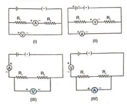
To verify Ohm's law, a student is provided with a test resistor RT, a high resistance R1, a small resistance R2, two identical galvanometer G1andG2, and a variable voltage source V. The correct circuit to carry out the experiment is


The correct Answer is:C
To verify Ohm.s law one galvanometer is used as ammeter and other galvanometer is used as voltmeter. Voltmeter should have high resistance and ammeter should have low resistance as voltmeter is used in parallel and ammeter in series that is in option (c).
Similar Questions
To verify Ohm's law, a student is provided with a test resistor RT, a high resistance R1 . a small resistance R2, two identical galvometers G1 and G2 and voltage source V. The correct circuit to carry out the experiment is.
View SolutionA cell and two resistors R_1 and R_2 are provided to you. Derive an expression for the effective resistance of the circuit in which current is the same in both resistors.
View SolutionA cell and two resistors R_1 and R_2 are provided to you. If R_1 = 4Ω and R_2 =6Ω . in which combination effective resistance is minimum? Find its value?
View SolutionTwo resistors of resistances R1 and R2 are connected in series and this group is connected across a voltage source of (V) volts. What are the voltages across R1andR2
View SolutionIn an experiment to determine equivalent resistance of two resistors R1 and R2 in series, which one of the following circuit diagrams shows the correct way of connecting the voltmetr in the circuit?

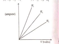
View SolutionA student carries out an experiment and plots of V-I graph of three samples of nichrome wire was resistance R1,R2 and R3 respectively. Which of the following is true?

View SolutionThe combined resistance of two resistors R1andR∘(R1,R2>0) is given by 1R=1R1+1R2. If R1+R2=C(a constant), show that maximum resistance R is obtained by choosing R1=R2
View SolutionTo verify Ohm's law, a student is provided with a test resistor R1 a high resistance R2 , a small resistance R two identical galvanometers G1 and G2, and a variable voltage source V. The correct circuit to carry out the experiment is:
View Solution
