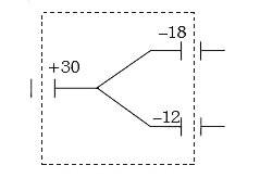
In the figure shown below, the charge on the left plate of the 10μF capacitor is −30μF. The change on the right plate of the 6μF capacitor is:

−12μC
+12μC
−18μC
+18μC
The correct Answer is:D
Applying the concept of charge conservation on isolated plates of 10μF,6μFand4μF and distributing the charge we get

=6(6+4)×30mC=+18μC.
Similar Questions
The capacity of a parallel plate air capacitor is 10muF and it is given a charge of 40muC . The electrical energy stored in the capacitor is
View SolutionIn the figure shown below, the charge on the left plate of the 10μF capacitor is −30μF. The change on the right plate of the 6μF capacitor is:

View Solutionदिखाए गए चित्र में 10 μF के संधारित्र की बाएँ प्लेट पर -30 μC आवेश है। 6 μF के संधारित्र की दाएँ प्लेट पर आवेश होगा

View SolutionIn the figure shown below ,the charge on the left plate of the 10mu F capacitor is -30 mu C. The charge on the right plate of the 6 muF capactior is :
View SolutionThe numerical value of the charge on either plates of capacitor 'C' as shown in the figure is

View Solutionदिए गए परिपथ के भाग में 5μF संधारित्र के बायीं प्लेट पर आवेश −20μC है, तो 3μF संधारित्र के दायी प्लेट पर आवेश होगा।

View SolutionAn air capacitor consists of two parallel plates B as shown in the figure. Plate A is given a change and plate B is given a charge 3Q. P is the median plane of the capacitor. If C_(0) is the capacitor capacitor, then
View SolutionThe expression for the capacity of the capacitor formed by compound dielectric placed between the plates of a parallel plate capacitor as shown in figure, will be (area of plate = A )
View Solution
