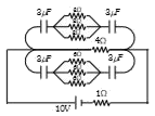
In the following figure, the charge on each condenser in the steady state will be

A
3μC
B
6μC
C
9μC
D
12μC
Video Solution
Text Solution
The correct Answer is:D
I=105=2A
V4Ω=2×4=8V
Potential difference across each capacitor is 4V
Q=3×4=12μC
|
Similar Questions
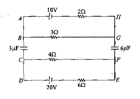
In the cirucit shown in figure-3.250, find the steady state charges on both the capacitors

View SolutionCalculate the charge on capacitor A in the circuit shown in figure-3.255 in steady state.
View SolutionIn the circuit shown in the figure, in steady state: The charge on 5 muF capacitor is
View SolutionThe magnitude of charge in steady state on either of the plates of condenser C in the adjoining circuit is
View SolutionIn the following figure, the charge on each condenser in the steady state will be -
View SolutionIn steady state, find the charge on the capacitor in (mu C) shown in figure.
View Solution
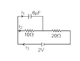
In steady state, find the charge on the capacitor shown in figure.
View SolutionIn the circuit shown in figure, find the steady state charges on oth the capacitors.
View Solution
