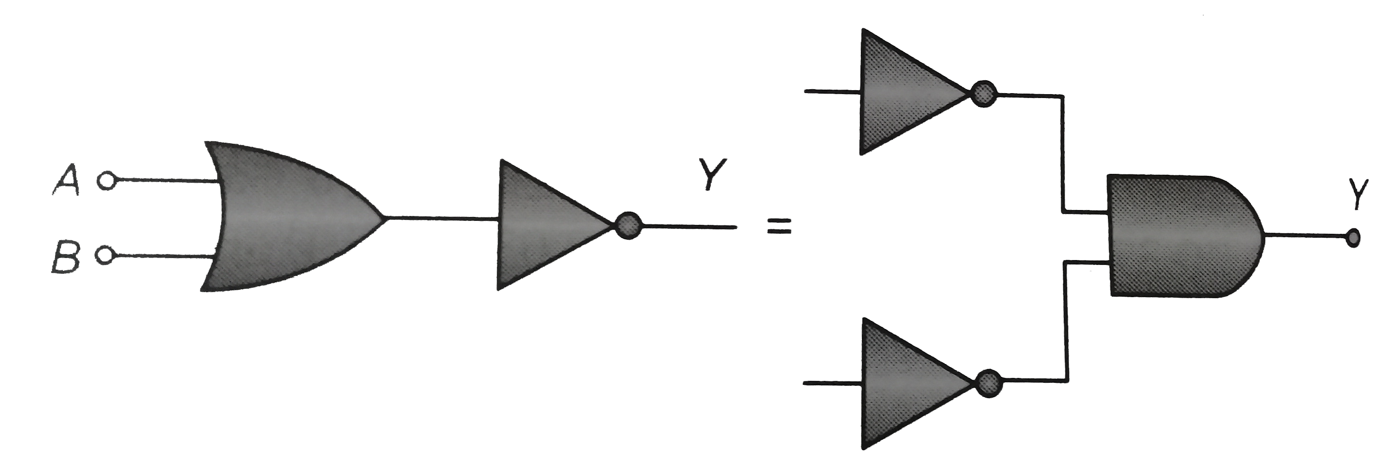
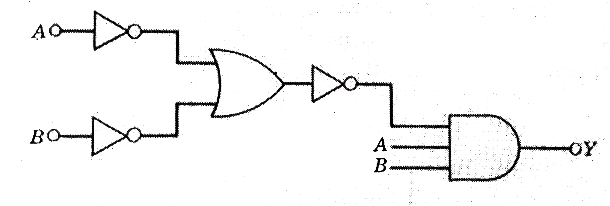
Assertion: De Morgan's theoram ¯¯¯¯¯¯¯¯¯¯¯A+B=¯¯¯A.¯¯¯B may be explained by the following circuit.
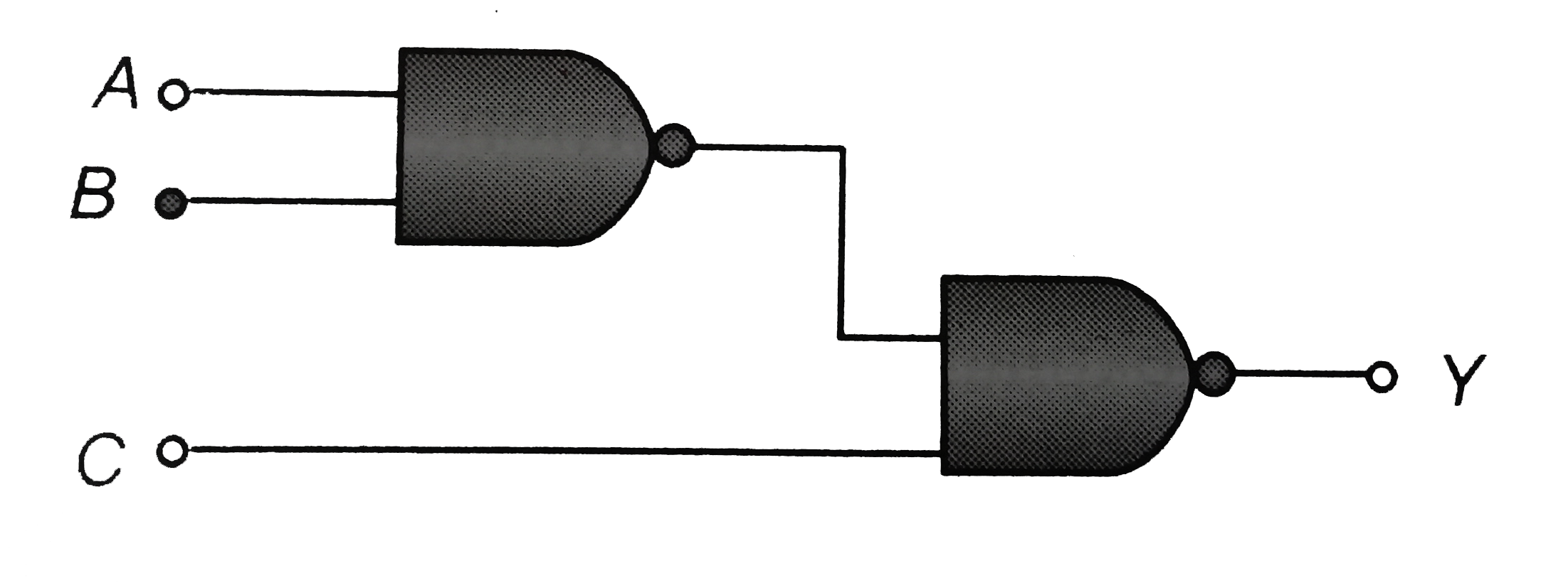
Reason: In the following circuit, for output, inputs ABC are 101.
If both assertion and reason are true and the reason is the correct explanation of the assertion.
If both assertion and reason are true but reason is not the correct explanation of the assertion.
If assertion is true but reason is false.
If the assertion and reason both are false.
The correct Answer is:C
Step by step video, text & image solution for Assertion: De Morgan's theoram bar(A+B)=bar(A).bar(B) may be explained by the following circuit. Reason: In the following circuit, for output, inputs ABC are 101. by Physics experts to help you in doubts & scoring excellent marks in Class 12 exams.
Updated on:21/07/2023Topper's Solved these Questions
- ELECTRONICSBOOK - ERRORLESSCHAPTER - ELECTRONICSEXERCISE - Past years questions
73 Videos
- ELECTRON, PHOTON, PHOTOELECTRIC EFFECT & X -RAYBOOK - ERRORLESSCHAPTER - ELECTRON, PHOTON, PHOTOELECTRIC EFFECT & X -RAYEXERCISE - ASSERTION & REASON
27 Videos
- ELECTROSTATICSBOOK - ERRORLESSCHAPTER - ELECTROSTATICSEXERCISE - ASSERTION & REASON
25 Videos
Similar Questions
Knowledge Check
In the following circuit the output Y becomes zero for the inputs
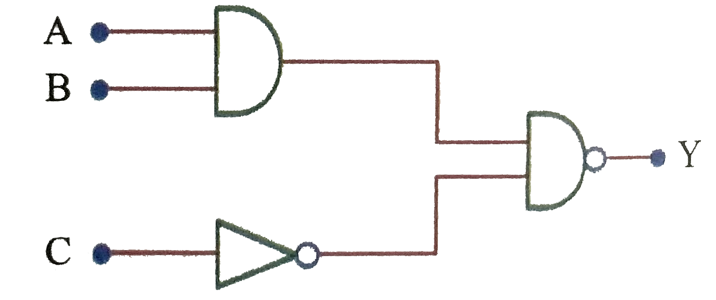 .AA=1,B=0,C=0BA=0,B=1,C=1CA=0,B=0,C=0DA=1,B=1,C=0
To get output 1 for the following circuit, the correct choice for the input is :
 AA=l,B=l,C=0A=1, B=1, C=0BA=1, B=0, C=1CA=0, B=1, C=0DA=1, B=0, C=0
To get output 1 for the following circuit, the correct choice for the input is:
 AA=0,B=1,C=0BA=1,B=0,C=0CA=1,B=1,C=0DA=1,B=0,C=1
Express by a truth table, the output Y for all possible input A and B in the following circuit Fig.
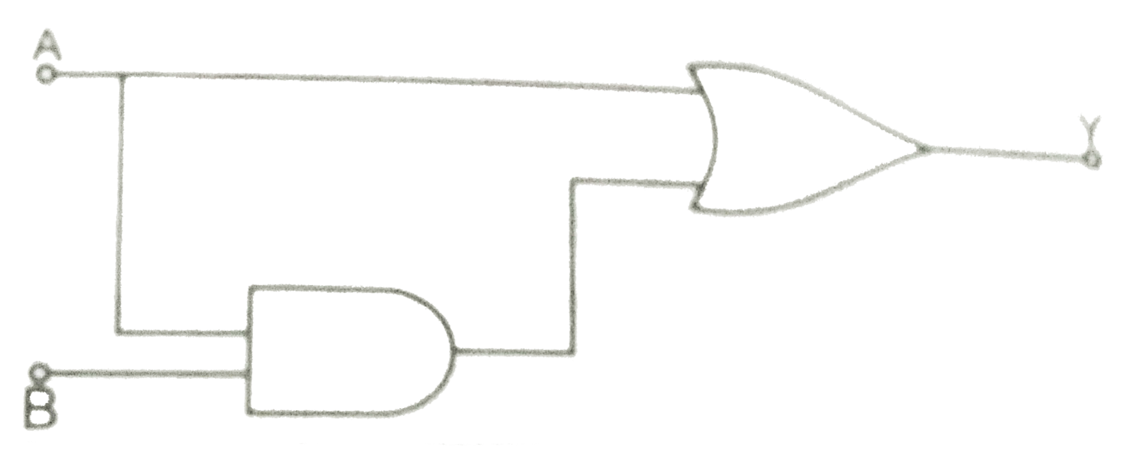
View SolutionFind the output Y of the following circuit if the inputs are: A=0,B=0,A=0,B=1,A=1,B=0,A=1,B=1
View SolutionWhat is the output Y in the following circuit, when all the three output A,B,C are first 0 and then 1?

View SolutionTo get output 1for the following circuit, the correct choice for the input is :

View SolutionTo get output 1 for the following circuit, the correct choice for the input is :

View Solution


