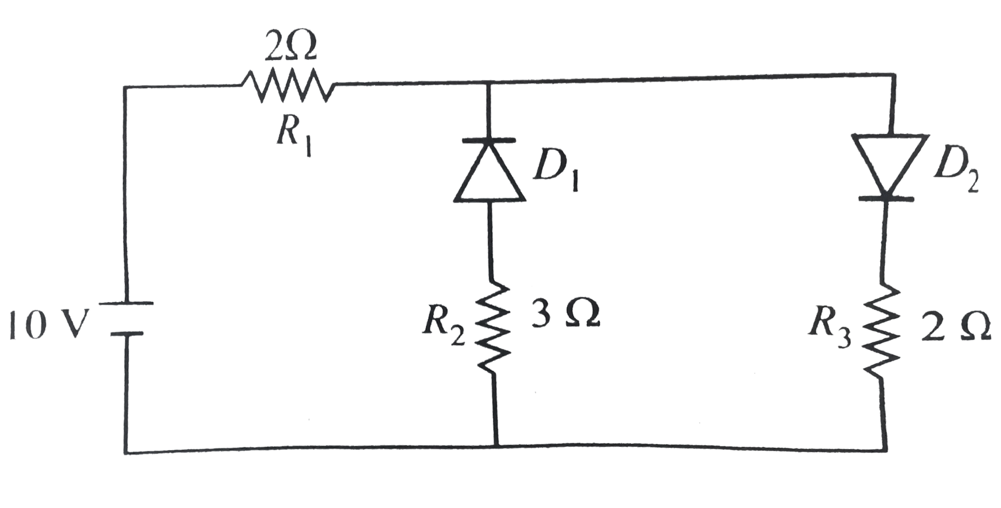
The given circuit has two ideal diodes connected as show in the figure. The current flowing through the resistance R1 will be
A
1.43A
B
3.13A
C
2.5A
D
10.0A
Video Solution
Text Solution
The correct Answer is:C
Current will not flow through D1 as it it reverse biased.
Current will flow through cell, R1,D2 and R3.
∴i=102+2=2.5A
|
Topper's Solved these Questions
- ELECTRONICSBOOK - ERRORLESSCHAPTER - ELECTRONICSEXERCISE - Assertion & Reason
26 Videos
- ELECTRONICSBOOK - ERRORLESSCHAPTER - ELECTRONICSEXERCISE - NCERT Based Questions (Digital Electronics)
23 Videos
- ELECTRON, PHOTON, PHOTOELECTRIC EFFECT & X -RAYBOOK - ERRORLESSCHAPTER - ELECTRON, PHOTON, PHOTOELECTRIC EFFECT & X -RAYEXERCISE - ASSERTION & REASON
27 Videos
- ELECTROSTATICSBOOK - ERRORLESSCHAPTER - ELECTROSTATICSEXERCISE - ASSERTION & REASON
25 Videos
Similar Questions
Knowledge Check
The given circuit has two ideal diodes connected as show in the figure. The current flowing through the resistance R1 will be
 A2.5 AB10.0 AC1.43 AD3.13 A
The given circuit has two ideal diodes connected as show in the figure. The current flowing through the resistance R1 will be
 A1.43AB3.13AC2.5AD10.0A
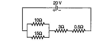
In the circuit, the current flowing through 10Ω resistance is
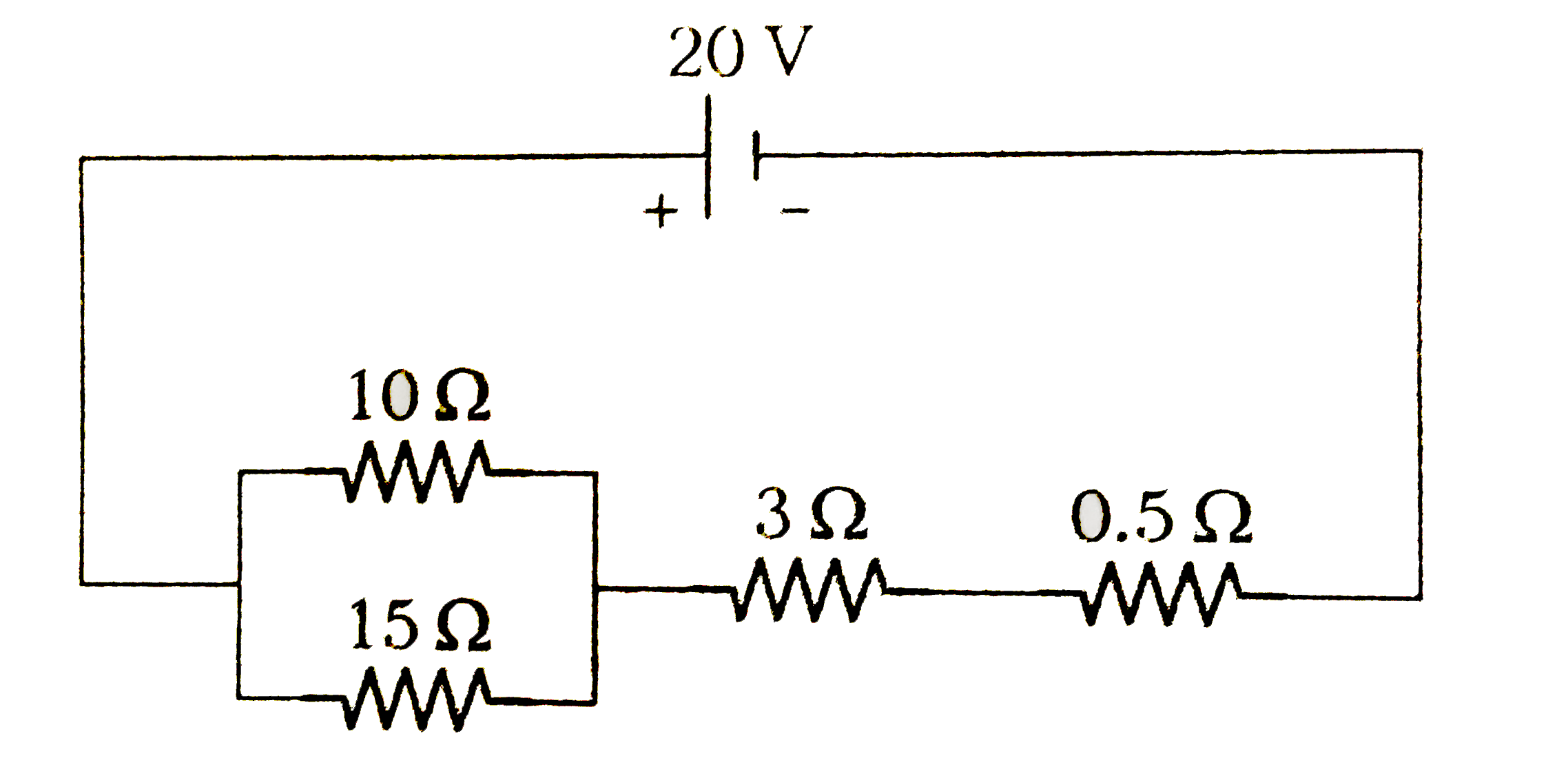 A12AB1.2AC0.8AD0.4A
4 ideal diodes are connected as shown in the circuit the current through 50Ω is.
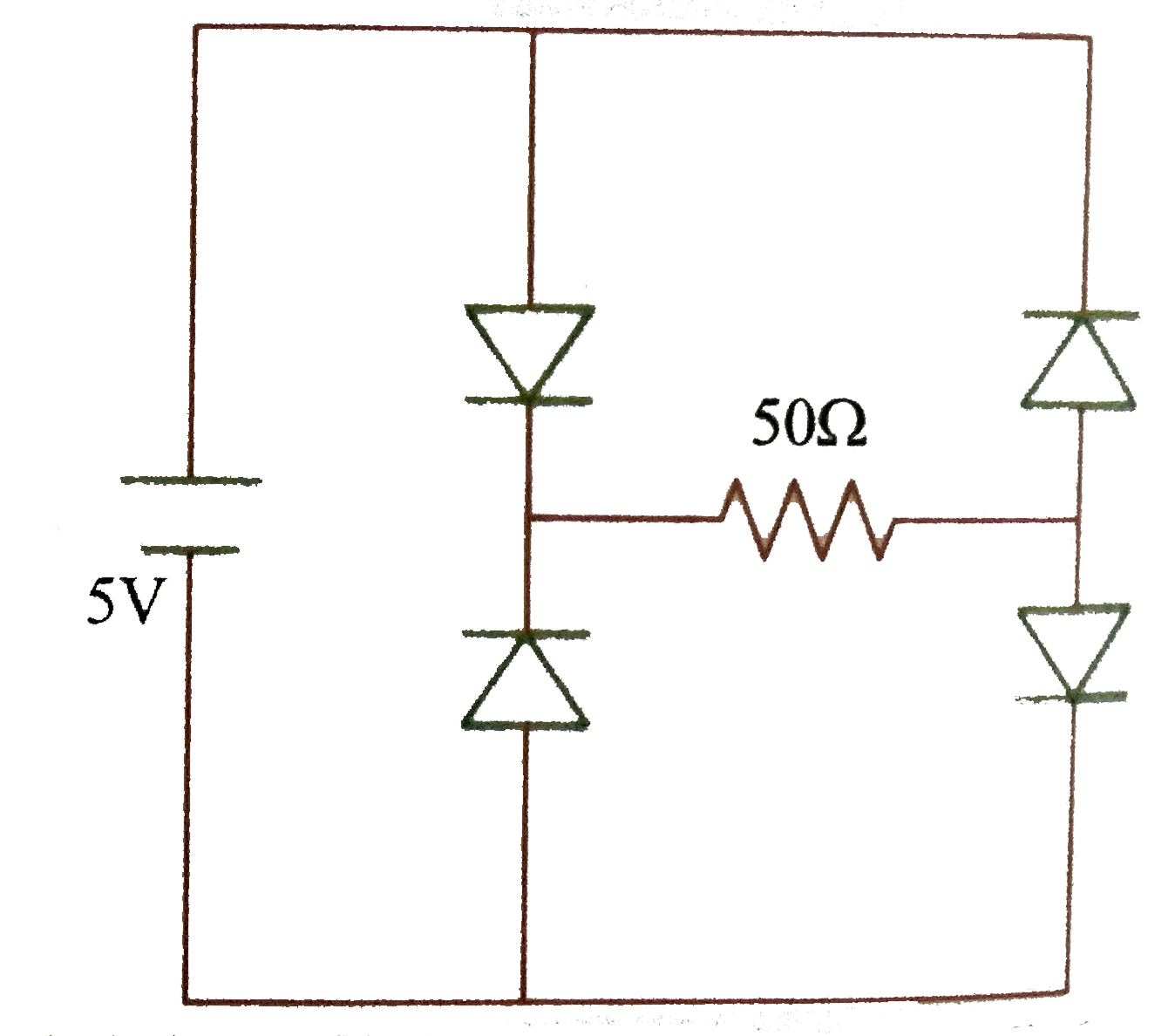 .
.
View SolutionIn the circuit, the current flowing through the zener diode is
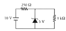
View SolutionThe current through the ideal diode as shown in the figure is

View SolutionThe current flowing through the zener diode in figure is -
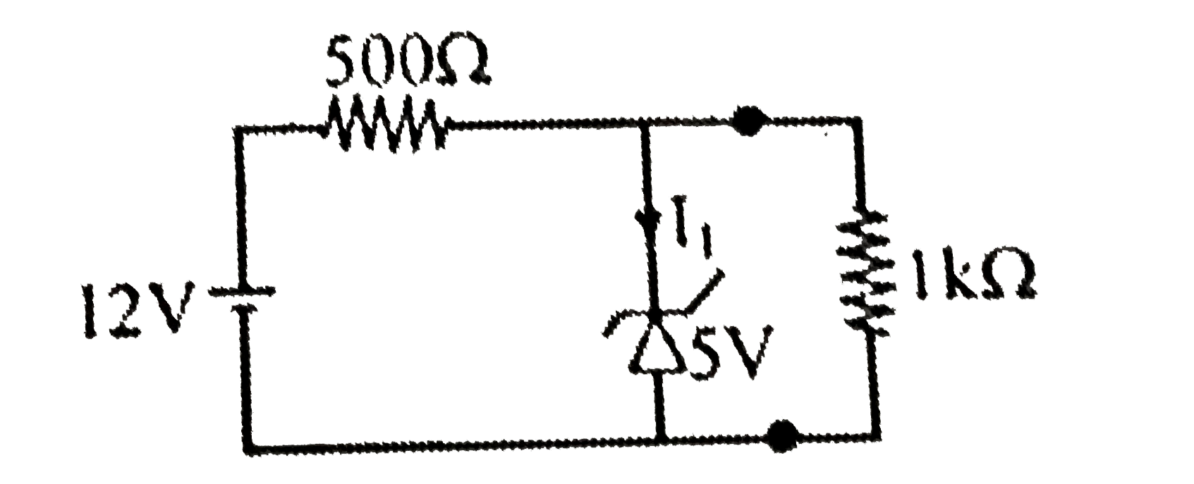
View SolutionIn the circuit in figure, the current flowing 5Ω resistance is :
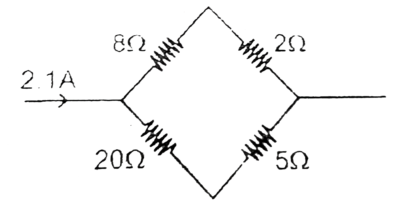
View Solution

