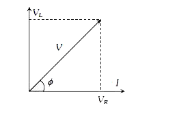
Assertion: An inductance and a resistance are connected in series with an AC circuit. In this circuit the current and the potential difference across the resistance lag behind potential difference across the inductance by an angle π/2.
Reason: In LR circuit voltage leads the current by phase angle which depends on the value of inductance and resistance both.
If both assertion and reason are true and the reason is the correct explanation of the assertion.
If both assertion and reason are true but reason is not the correct explanation of the assertion.
If assertion is true but reason is false.
If the assertion and reason both are false
The correct Answer is:B
As both the inductance and resistance are joined in series, hence current through both will be same. But in case of resistance, both the current and potential vary simultaneously, hence they are in same phase

In case of an inductance when current is zero, potential difference across it is maximum and when current reaches maximum (at ωt=π/2) potential difference across it becomes zero, i.e., potential difference leads the current by π/2 or current lags behind the potential difference by π/2 . Phase angle in case of LR circuit is given as ϕ=tan−1(ωLR)
Topper's Solved these Questions
Similar Questions
Knowledge Check
- Question 1 - Select One
An inductance and a resistance are connected in series with an AC potential . In this circuit
Athe current and the potential difference across the resistance lead the PD across the inductive by phase angle π/ 2Bthe current and the potential difference across the resistance lag behind PD across the inductance by an angle π/ 2Cthe current and the potential difference across the resistance lag behind in PD across the inductance by an anle πDthe PD across the resistance lags behind the PD across the inductance by an angle π/ 2 but the current in the resistance leads the PD across inductance by π/ 2 - Question 2 - Select One
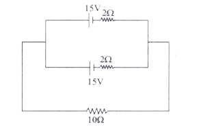
For the circuit shown in the figure what is the potential difference across the external resistance ?
 A10VB7.5 VC15 VD30V
 - Question 3 - Select One
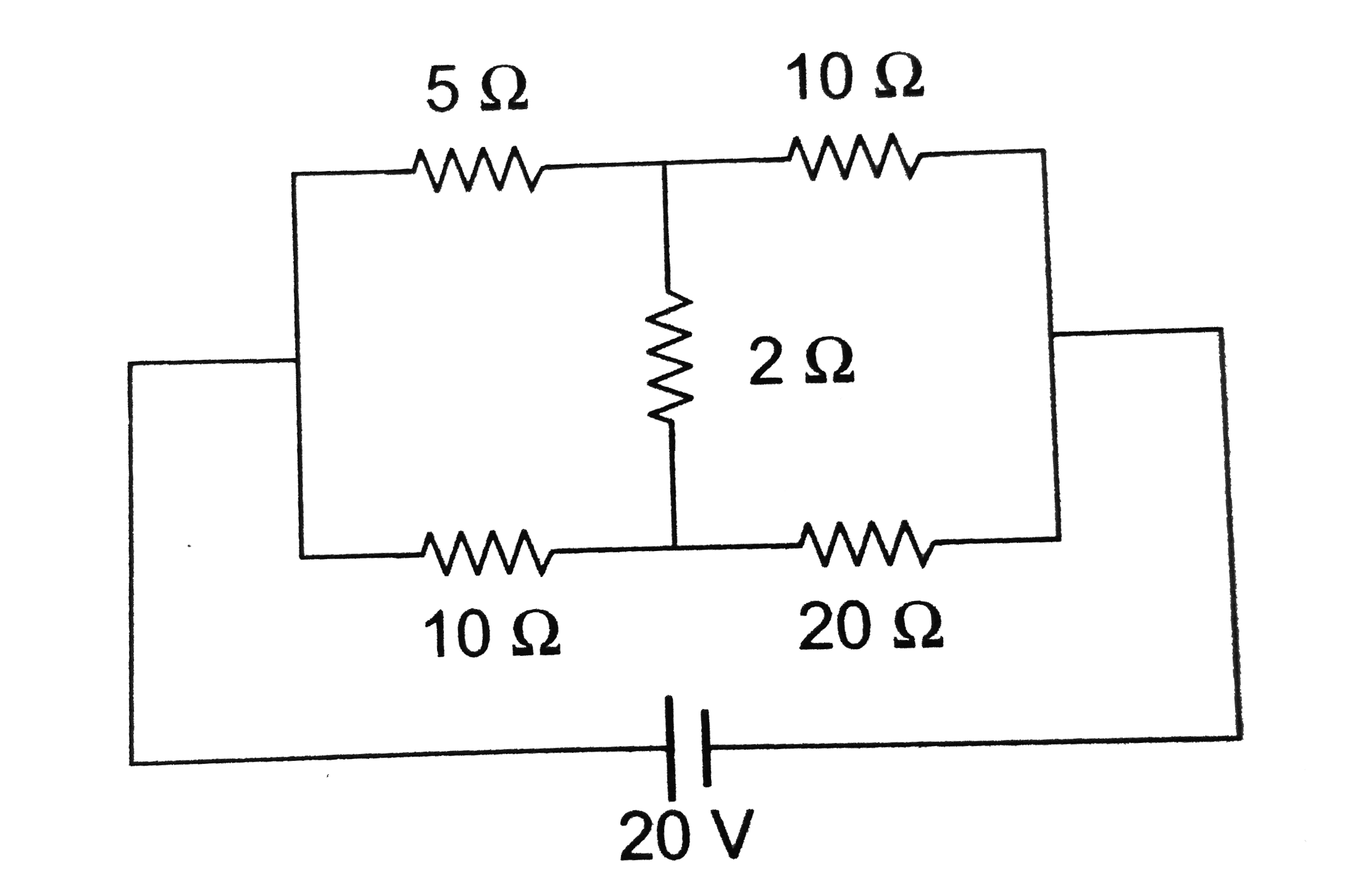
In the given circuit diagram, potential difference across 2Ω resistance is
 A4VB6VC20VDzero
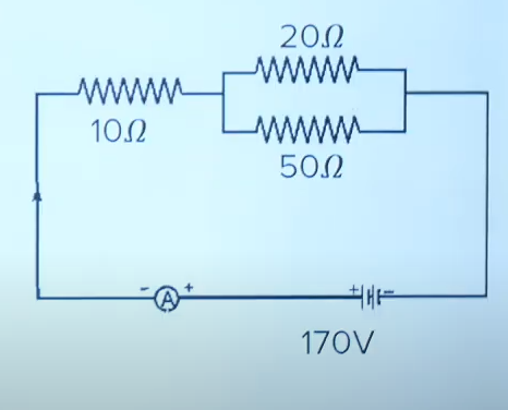
To measure the current and potential difference of the resistances connected in series in a circuit, we will use
View SolutionTo measure the current and potential difference of the resistances connected in series in a circuit, we will use
View SolutionAn alternating voltage is connected in series with a resistance R and inductance L if the potential drop across the resistance is 200V and across the inductance is 150V, then the applied voltage is
View SolutionAn alternating e.m.f. of 100V (rms) is applied to a series LCR circuit. At resonance, the potential difference across the inductance and across the capacitance is 400V each. The potential difference across the resistance will be
View SolutionThe potential differences across the resistance, capacitance and inductance are 80V, 40V and 100V respectively in an L-C-R circuit. The power factor of this circuit is
View Solution

