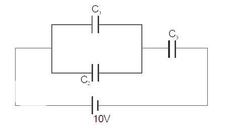
The combination of capacitors with C1=3μF,C2=4μFandC3=2μF is charged by connecting AB to a battery.
Consider the following statements
I. Energy stored in C1 = Energy stored in C2 + Energy stored in C3
II. Charge on C1= Charge on C2+ Charge on C3
III. Potential drop across C1= Potential drop across C2= Potential drop across C3
Which of these is/are correct

I and II
II only
I and III
III only
The correct Answer is:B

CAB=3×69=2μF
Q=CABV=2VμC
Q1=Q2+Q3→ correct → (II)
V1=69×V=2V3,V2=V3=V3→ incorrect (III)
U1=12C1V21=2V23,U2=12C2V22=2V29
U3=12C3V23=V29
∴U2+U3=V23≠U1→(I)→ incorrect.
Topper's Solved these Questions
- ELECTROSTATICSBOOK - ERRORLESSCHAPTER - ELECTROSTATICSEXERCISE - PAST YEARS QUESTIONS
56 Videos
- ELECTROSTATICSBOOK - ERRORLESSCHAPTER - ELECTROSTATICSEXERCISE - ASSERTION & REASON
25 Videos
- ELECTROSTATICSBOOK - ERRORLESSCHAPTER - ELECTROSTATICSEXERCISE - NCERT BASED QUESTIONS (Capacitance)
59 Videos
- ELECTRONICSBOOK - ERRORLESSCHAPTER - ELECTRONICSEXERCISE - Assertion & Reason
26 Videos
- MAGNETIC EFFECTS OF CURRENT BOOK - ERRORLESSCHAPTER - MAGNETIC EFFECTS OF CURRENT EXERCISE - ASSERTION & REASON
18 Videos
Similar Questions
Knowledge Check
Three capacitors C1=1μF,C2=2μFandC3=3μF are connected as shown in figure, then the equivalent capacitance between points A and B is
 A3μFB4μFC5μFD6μF
The ratio of energy stored in capacitors C1 and C2
 A98B89C56D65
A capacitor of capacitance 13μF is connected to a battery of 300volt and charged. Then the energy stored in capacitor is
A3×10−2 JouleB1.5×10−2 JouleC6×102 JouleD12×102 Joule
Three identical capacitors C1,C2 and C3 of capacitance 6μF each are connected to a 12 V battery as shown in Fig
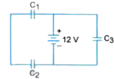
energy stored in the network of capacitors .
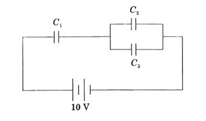
View SolutionThe figure shows a network of three capacitors C1=2μF,C2=6μFandC3=3μF connected across a battery of 10 V. calculate the charge acquired by C1.
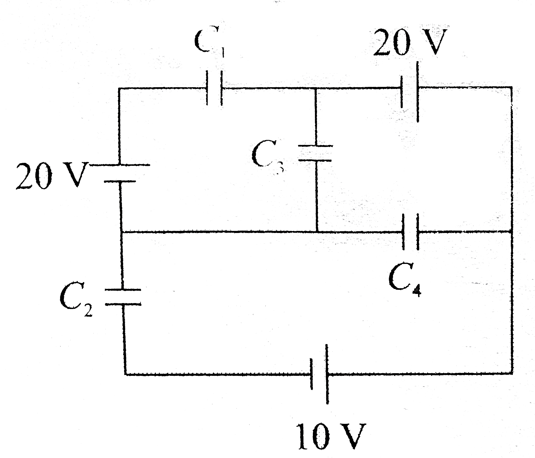
View SolutionFour capacitors C1=8μF,
C2=2μf,C3=6μF, and C4=6,μF are arranged as shown in. Find the charge on all the capacitors in the circuit.
 .
.
View SolutionTwo capacitorsC1=4μFandC2=2μF are charged to same potential V = 500 Volt, but with opposite polarity as shown in the figure. The switches S1andS2are closed.
View SolutionCapacitors C1=1μF and C2=2μF are separately charged from the same battery. They are allowed to discharge separately through equal resistors
View Solution

