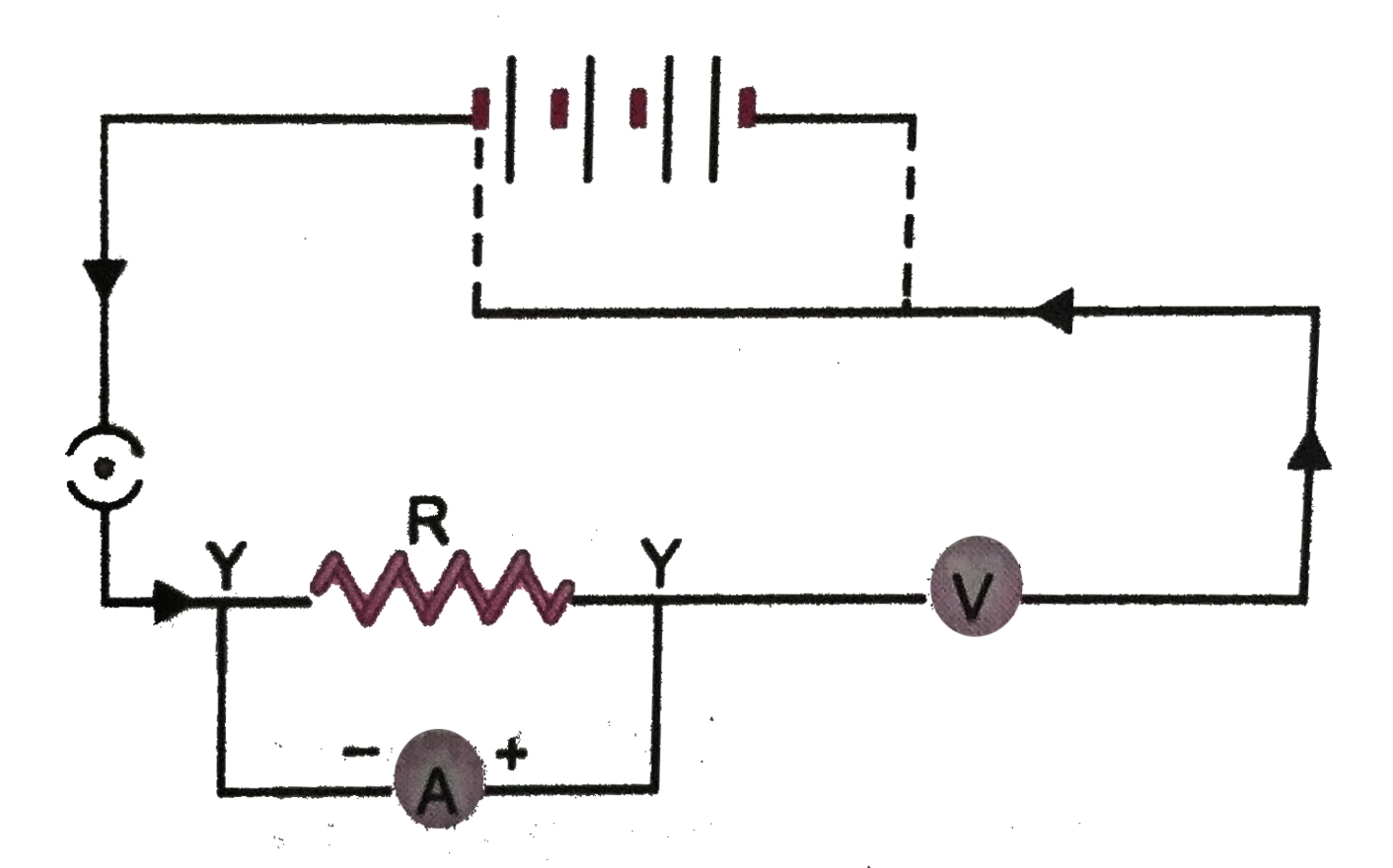
A child has drawn the electric circuit to study Ohm's law as shown in (Fig. 3.42). His teacher told him that the circuit diagram needs correction. Study the circuit diagram and redraw it after making all corrections.
 .
.
In electrical circuit, Voltmeter should be connected in parallel and ammeter should be connected in series. Because ammeter measures current through elements and voltmeter measures voltage across the element. From the circuit diagram we can see that sign convention of given diagram is wrong. That.s why we need to correct The correct circuit diagram is given below

Similar Questions
A student has drawn the electric circuit to study Ohm's law as shown in figure. His teacher told that the circuit diagram needs correction. Study the circuit diagram and redraw it after making all corrections.
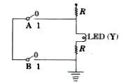
View SolutionThe correct booleon operation represented by the circuit diagram drawn is
View Solution
Knowledge Check
Study the following circuit diagram in fig. 5.320 and mark the correct options.
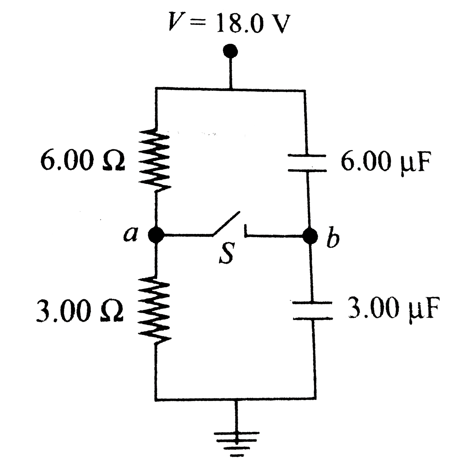 AThe potential of point a with respect to point b in the figure when swithc S is open is - 6V.BThe points a and b are at the same potential, when S is opened.CThe charge flowing through switch S when it is closed is 54μC.DThe final potential of b with respect to ground when switch S is closed is 8V.
The correct Boolean operation represented by the circuit diagram drawn is
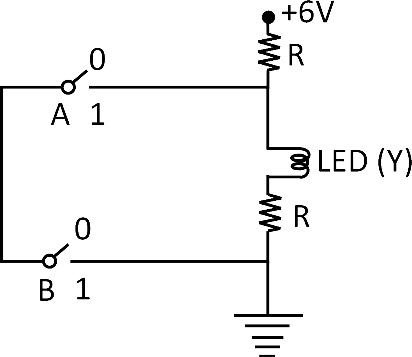 ANORBANDCORDNAND
The correct Boolean operation represented by the circuit diagram drawn is
 ANORBANDCORDNAND
To study the dependence of potential difference (V) on current I across Resistor (R), Four circuit diagrams are prepared.
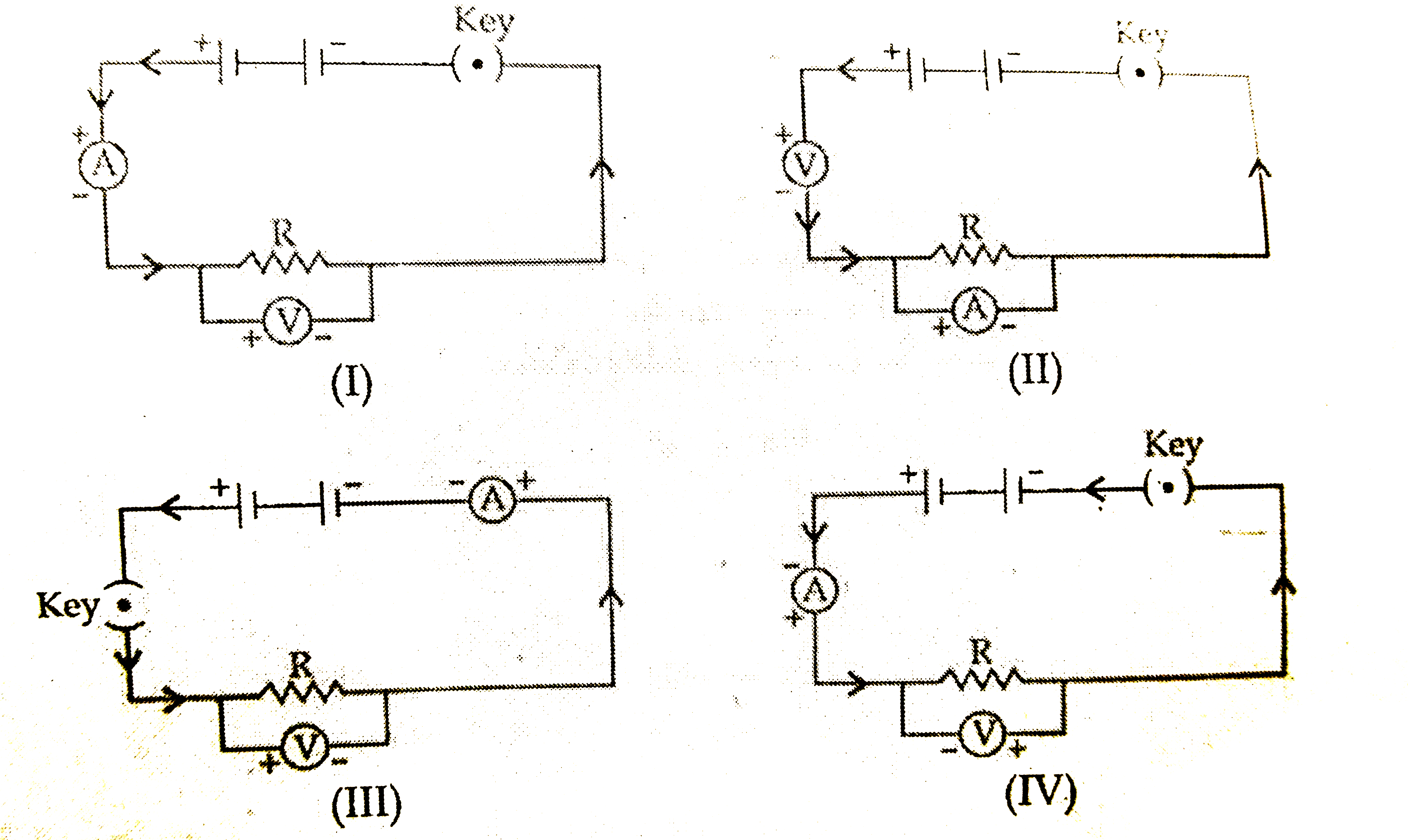
(i) Select the circuit diagrams which are correct.
(ii) Give reason for the circuit diagrams which are not correct.
View SolutionTo determine the equivalent resistance of two resistors when connected in series, a student arrnaged the circuit components as shown in (Fig. 3.63) But he did not succeed to achieve the objective. Which mistake has been committed by him in setting up the circuit ?
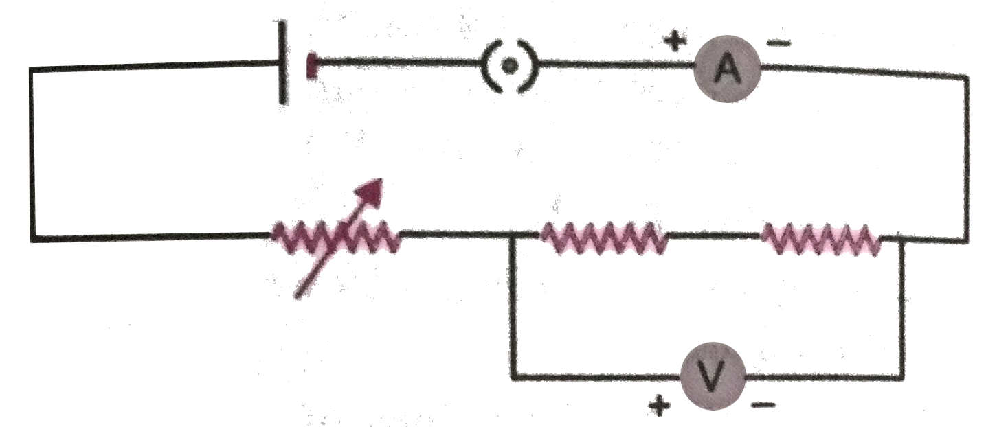 .
.
View Solution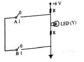
The correct boolean operation represented by the circuit diagram drawn is :
View SolutionCarefully study the circuit diagram shown and calculate the value of x.
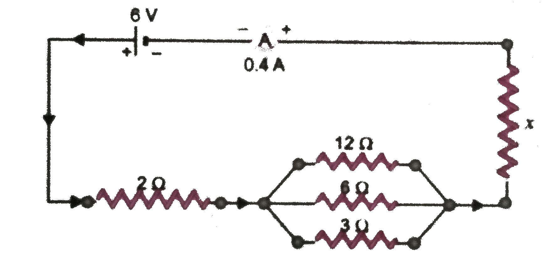 .
.
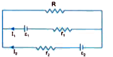
View SolutionSee the electrical circuit shown in Fig. Which of the following equations is a correct equation for it ?
View Solution
