In figure, assuming the diodes to be ideal, 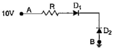
D1andD2 are both forward biased and hence current flows from A to B
D1andD2are both reverse biased and hence no current flows from A to B
D1 is forward biased and D2 is reverse biased and hence current flows from A to B
D2 is forward biased and D1 is reverse biased and hence no current flows from B to A
Step by step video solution for In figure, assuming the diodes to be ideal, by Physics experts to help you in doubts & scoring excellent marks in Class 12 exams.
Updated on:21/07/2023Topper's Solved these Questions
- SEMICONDUCTOR DEVICESBOOK - AAKASH SERIESCHAPTER - SEMICONDUCTOR DEVICESEXERCISE - EXERCISE - IB
7 Videos
- SEMICONDUCTOR DEVICESBOOK - AAKASH SERIESCHAPTER - SEMICONDUCTOR DEVICESEXERCISE - EXERCISE - II
17 Videos
- SEMICONDUCTOR DEVICESBOOK - AAKASH SERIESCHAPTER - SEMICONDUCTOR DEVICESEXERCISE - PROBLEMS
41 Videos
- RAY OPTICSBOOK - AAKASH SERIESCHAPTER - RAY OPTICSEXERCISE - PROBLEMS ( LEVEL-II)
60 Videos
- UNITS AND MEASUREMENTBOOK - AAKASH SERIESCHAPTER - UNITS AND MEASUREMENTEXERCISE - PRACTICE EXERCISE
45 Videos
Similar Questions
Knowledge Check
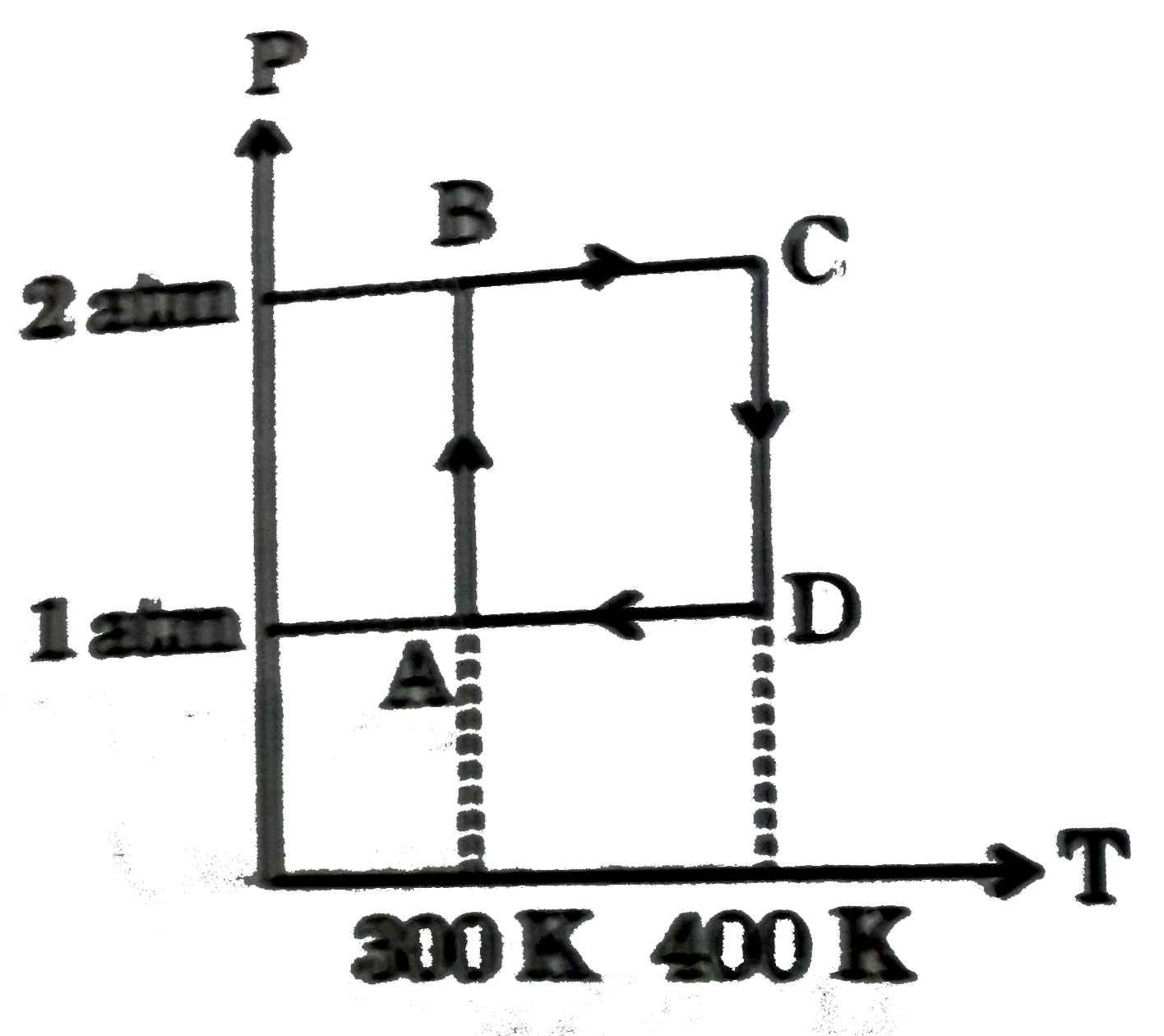
Two moles of Helium gas undergo a reversible cyclic process as shown in figure. Assuming gas to be ideal, what is the net work involved in the cyclic process ?
 A200R ln2B100R ln2C300R ln2D400R ln2
Two moles of Helium gas undergo a reversible cyclic process as shown in figure. Assuming gas to be ideal, what is the net work involved in the cyclic process ?
 A200 Rln2B100 Rln2C300 Rln2D400 Rln2
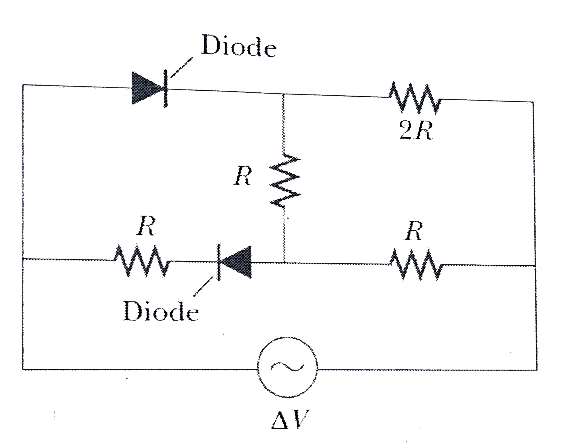
A diode is a device that allows current to be carried in only one direction (the direction indicated by the arrowhead in its circuit symbol). Find (approximately) in terms of ΔV and R the average power delivered to the diode circuit of the figure. Assume that the diodes are ideal and ΔV is the rms voltage applied to the circuit.
View Solution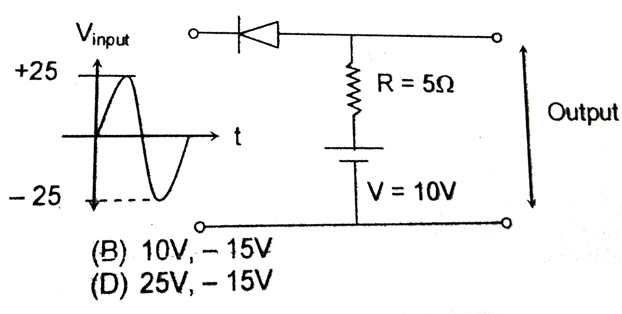
An ideal diode is connected in a circuit with resistance R=5Ω and V=10 volt as shown in figure maximum and minimum value of output voltage. When no load applied is (assume diode to be ideal)
View SolutionIn the circuit shown, the average power dissipated in the resistor is (assume diode to be ideal)
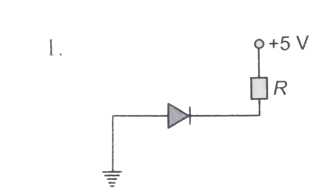
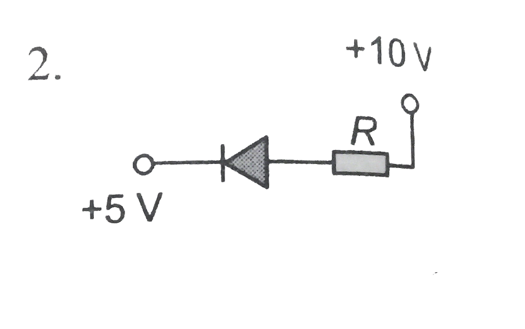
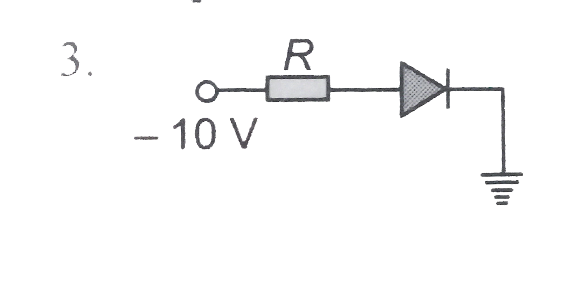
View SolutionIn the given figure, which of the diodes are forward biased?
View SolutionCalculate the current l in the following circuit, if all the diodes are ideal. All resistances are 200Ω
View SolutionA fullwave P.N diode rectifier used load resistor of 1500Ω. No filter is used. Assume each diode to have idealized characteristic with Rf=10Ω and Rr=ac. Since wave voltage applied to each diode has amplitude of 30 volts and frequency 50 Hz. Calculate.
(i) Peak, d.c rms load current
(ii) d.c power output
(iii) A.C power input
(iv) Rectifier efficiency.
View Solution

