Four identical capacitors each rates as 10μF−10V are supplied to you to obtain capacitor of 10μF−20V, we should connect them in
two rows each containing 2 condensers
four rows each containing 1 condenser
one row containing four condensers
all the above
The correct Answer is:A
To solve the problem of obtaining a capacitor of 10 µF - 20 V using four identical capacitors rated at 10 µF - 10 V, we need to determine the correct configuration to achieve the desired capacitance and voltage rating.
1. Understanding the Capacitor Ratings:
Each capacitor has a capacitance of 10 µF and a voltage rating of 10 V. We want to achieve a total capacitance of 10 µF and a voltage rating of 20 V.
2. Voltage Requirement:
To achieve a voltage rating of 20 V, we can connect capacitors in series. When capacitors are connected in series, the total voltage rating is the sum of the individual voltage ratings.
3. Capacitance in Series:
When capacitors are connected in series, the equivalent capacitance (C_eq) is given by the formula:
1Ceq=1C1+1C2+…+1Cn
For two capacitors in series, this simplifies to:
Ceq=Cn
where n is the number of capacitors in series.
4. Connecting Two Capacitors in Series:
If we connect two capacitors in series, the equivalent capacitance will be:
Ceq=10μF2=5μF
The voltage rating will be:
Vtotal=10V+10V=20V
5. Creating Two Sets of Series Capacitors:
Now we can create two sets of these series capacitors. Each set will have an equivalent capacitance of 5 µF and a voltage rating of 20 V.
6. Connecting the Two Sets in Parallel:
If we connect these two sets of 5 µF capacitors in parallel, the equivalent capacitance will be:
Ceq=5μF+5μF=10μF
The voltage rating remains at 20 V.
7. Final Configuration:
Therefore, the final configuration to achieve a capacitor of 10 µF - 20 V is to connect two rows, each containing two capacitors in series, and then connect these two rows in parallel.
Conclusion:
The correct answer is to connect the capacitors in two rows, each containing two capacitors in series.
Each capacitor has a capacitance of 10 µF and a voltage rating of 10 V. We want to achieve a total capacitance of 10 µF and a voltage rating of 20 V.
To achieve a voltage rating of 20 V, we can connect capacitors in series. When capacitors are connected in series, the total voltage rating is the sum of the individual voltage ratings.
When capacitors are connected in series, the equivalent capacitance (C_eq) is given by the formula:
1Ceq=1C1+1C2+…+1Cn
For two capacitors in series, this simplifies to:
Ceq=Cn
where n is the number of capacitors in series.
If we connect two capacitors in series, the equivalent capacitance will be:
Ceq=10μF2=5μF
The voltage rating will be:
Vtotal=10V+10V=20V
Now we can create two sets of these series capacitors. Each set will have an equivalent capacitance of 5 µF and a voltage rating of 20 V.
If we connect these two sets of 5 µF capacitors in parallel, the equivalent capacitance will be:
Ceq=5μF+5μF=10μF
The voltage rating remains at 20 V.
Therefore, the final configuration to achieve a capacitor of 10 µF - 20 V is to connect two rows, each containing two capacitors in series, and then connect these two rows in parallel.
The correct answer is to connect the capacitors in two rows, each containing two capacitors in series.
Topper's Solved these Questions
- APPENDICES ( REVISION EXERCISE )BOOK - AAKASH SERIESCHAPTER - APPENDICES ( REVISION EXERCISE )EXERCISE - REVISION EXERCISE (CUTTENT ELECTRICITY )
108 Videos
- APPENDICES ( REVISION EXERCISE )BOOK - AAKASH SERIESCHAPTER - APPENDICES ( REVISION EXERCISE )EXERCISE - REVISION EXERCISE (MOVING CHANGES & MEGNETISM)
95 Videos
- APPENDICES ( REVISION EXERCISE )BOOK - AAKASH SERIESCHAPTER - APPENDICES ( REVISION EXERCISE )EXERCISE - REVISION EXERCISE (MAGNETISM AND MATTER )
52 Videos
- ALTERNATING CURRENTBOOK - AAKASH SERIESCHAPTER - ALTERNATING CURRENTEXERCISE - EXERCISE - III
24 Videos
- APPENDICES (REVISION EXERCISE)BOOK - AAKASH SERIESCHAPTER - APPENDICES (REVISION EXERCISE)EXERCISE - LAW OF MOTION
128 Videos
Similar Questions
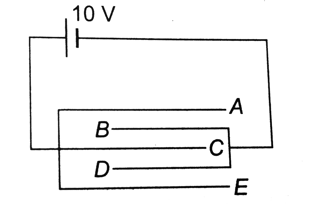
Five identical capacitor plates are arranged such that they make four capacitors each of 2μF. The plates are connected to a source of emf 10V. The charge on plate C is

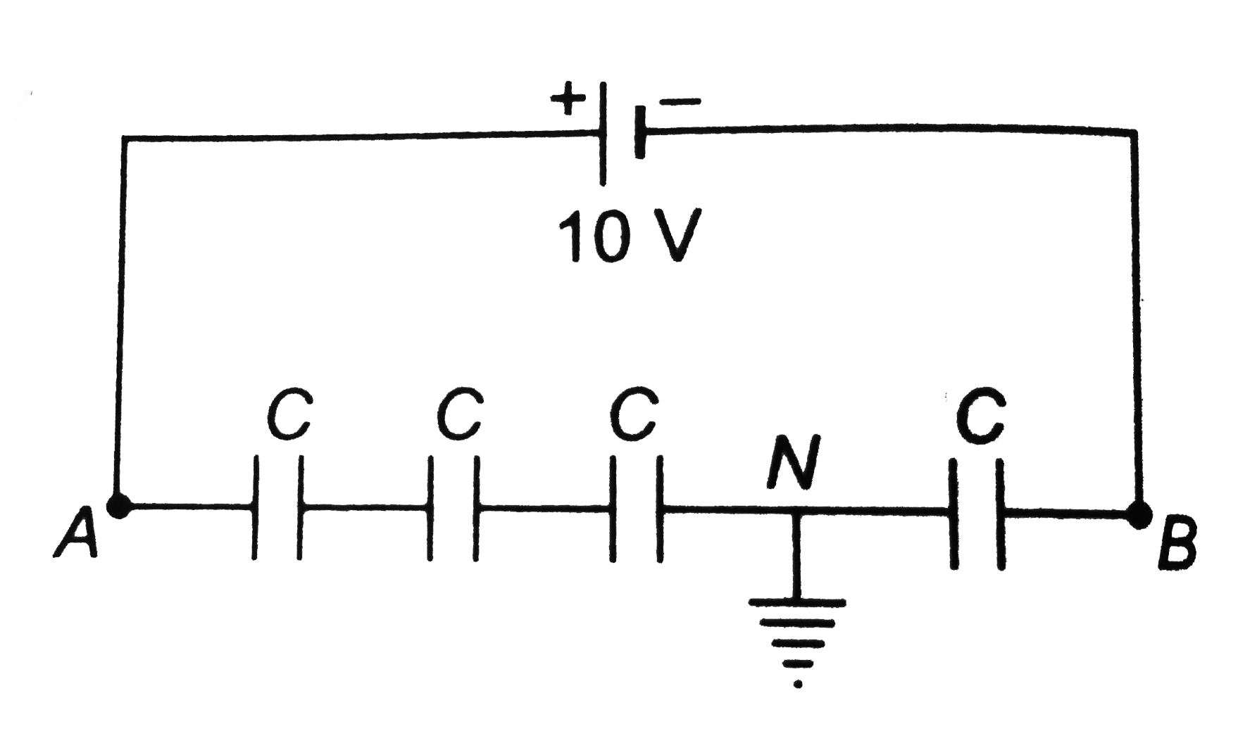
View SolutionFour identical capacitors are connected in series with a 10V battery as shown in the figure. The point N is earthed. The potentials of points A and B are

View Solution
Knowledge Check
Two capacitrors of 2μFand4μF are connected in parallel. A third capacitor of 6μF is connected in series. The combaination is connected across a 12 V battery. The voltage across 2μF capacitor is
A2 VB8 VC6 VD1 VA 30μF capacitor is connected to a 150 V, 60 Hz ac supply. The rms value of current in the circuit is
A17 AB1.7AC1.7mAD2.7A
Minimum number of capacitors each of 8μF and 250 V used to make a composite capacitor of 16μF and 1000 V are
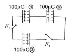
View SolutionThree identical charged capacitors each of capacitance 5 μF are connected as shown in figure. Potential difference across capacitor (3), long time after the swithces K1andK2 are closed , is

View SolutionA 10μF capacitor and a 20μF capacitor are connected in series across a 200V supply line. The chraged capacitors are then disconnected from the line and reconnected with their positive plates together and negative plates together and no external voltage is applied. what is the potential difference across each capacitor ?
View SolutionA 10μF capacitor and a 20μF capacitor are connected in series across a 200V supply line. The chraged capacitors are then disconnected from the line and reconnected with their positive plates together and negative plates together and no external voltage is applied. what is the potential difference across each capacitor ?
View SolutionA 100μF capacitor is charged to a potential difference of 24V. It is connected to an uncharged capacitor of capacitance 20μF What will be the new potential difference across the 100μF capacitor?
View SolutionA capacitor of capacitance 2.0μF is charged to a potential difference of 12 V. It is then connected to an uncharged capacitor of capacitance 4.0μF. Find (a) the charge flow through connecting wire upto study strate on each of the two capacitors after the connection in μC (b) The total electrostatic energy stored in both capacitors in μJ (c) the heat produced during the charge transfer from one capacitor to the other in μJ.
View Solution

