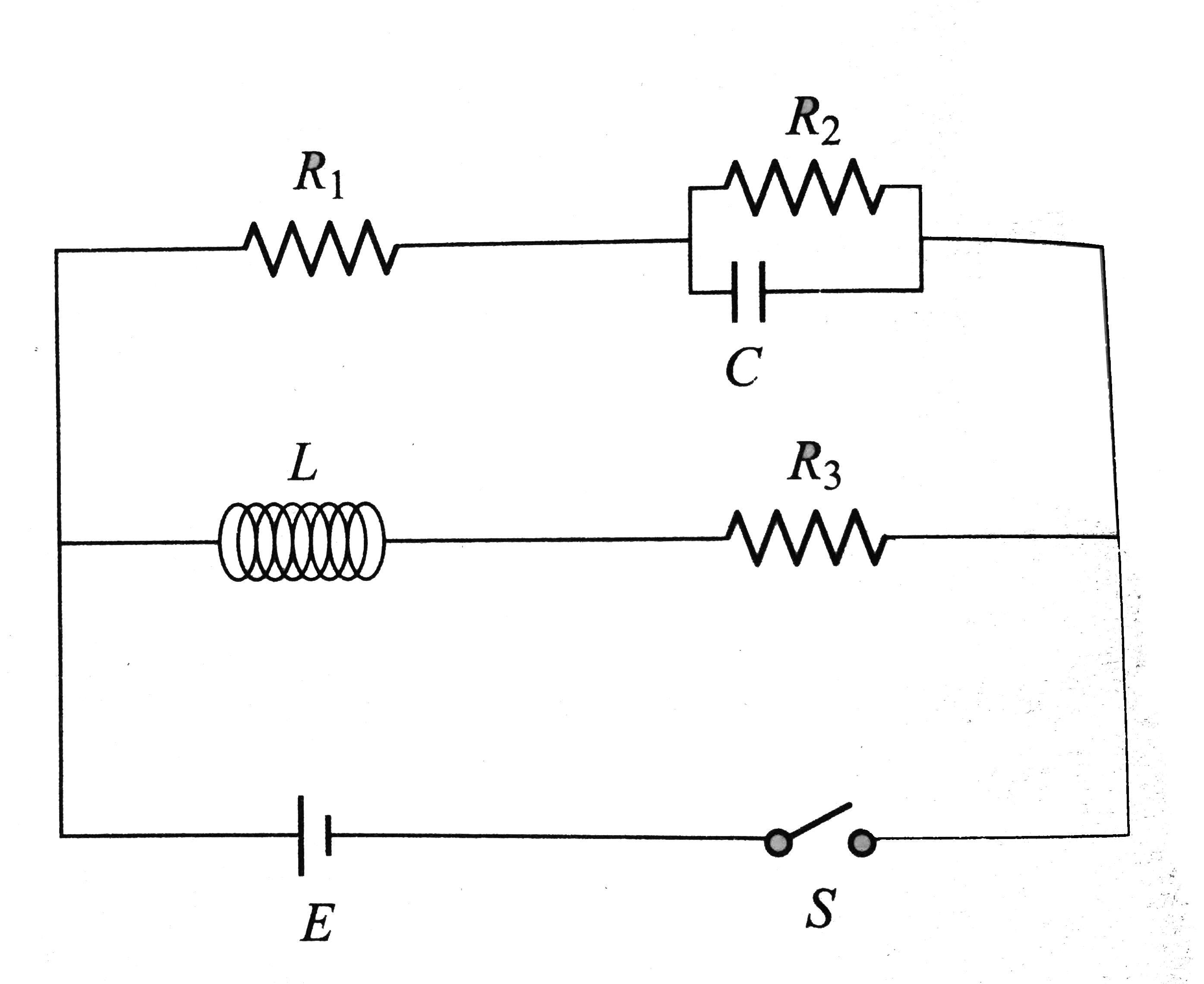
In the circuit shownin figure switch S is closed at time t=0. Find the current through different wire and charge stored on the capacitor at any time t.
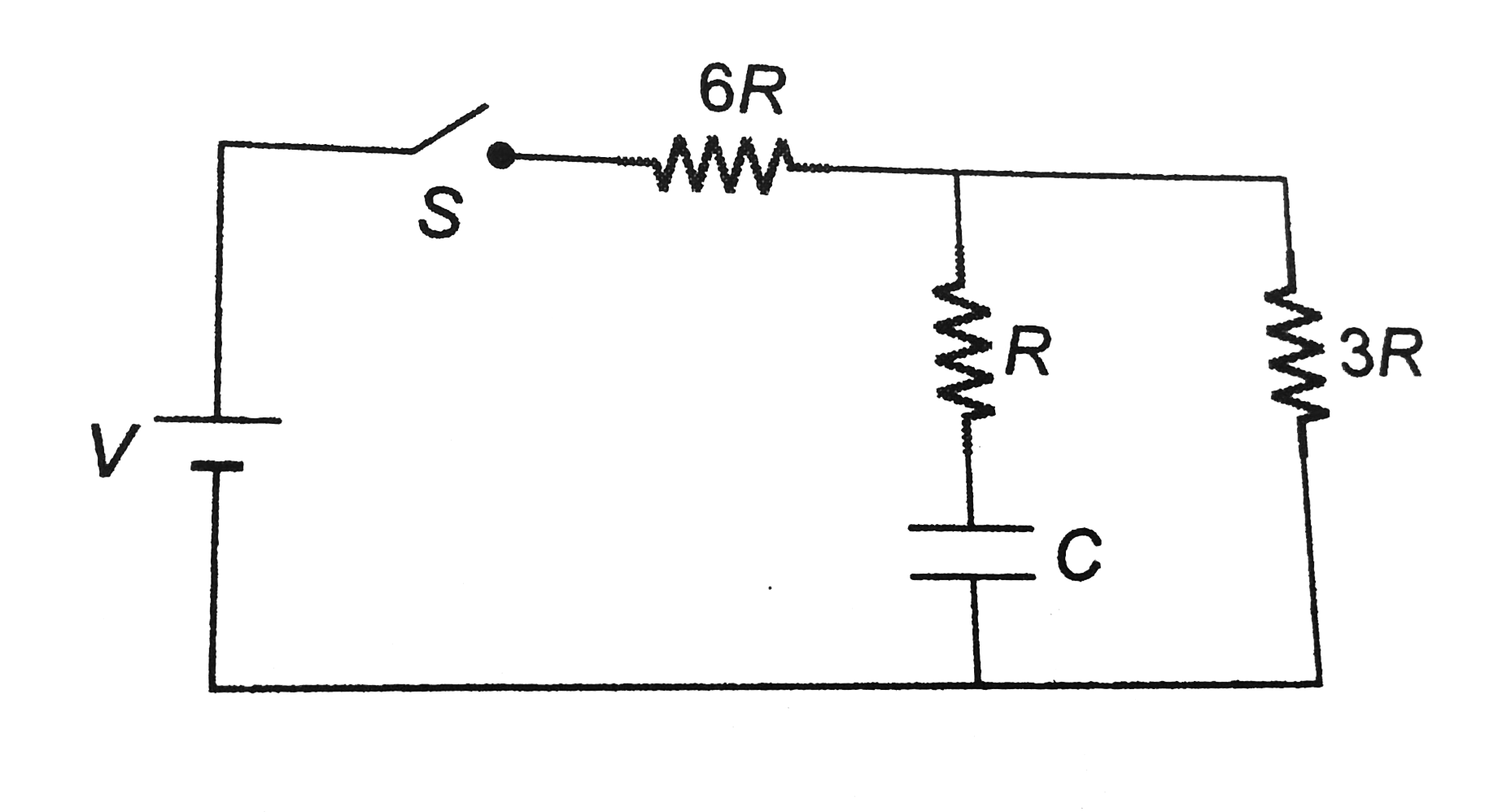
Calculation of equivalent time constant

In the circuit shown in figure, after short circuiting the battery 3R and OR are parallel, so their combined resistance is (6R)(3R)6R+3R=2R . Now this 2R is in series with the remain.
Hence ,Rnet=2R+R=3R
τ=(RnetC=3RC
Topper's Solved these Questions
- ELECTROMAGNETIC INDUCTIONBOOK - AAKASH SERIESCHAPTER - ELECTROMAGNETIC INDUCTIONEXERCISE - EXERCISE-IA
58 Videos
- ELECTROMAGNETIC INDUCTIONBOOK - AAKASH SERIESCHAPTER - ELECTROMAGNETIC INDUCTIONEXERCISE - EXERCISE-IB
18 Videos
- ELECTRIC FIELD AND POTENTIALBOOK - AAKASH SERIESCHAPTER - ELECTRIC FIELD AND POTENTIALEXERCISE - PROBLEMS (LEVEL-II)
26 Videos
- ELECTROMAGNETIC WAVESBOOK - AAKASH SERIESCHAPTER - ELECTROMAGNETIC WAVESEXERCISE - EXERCISE -II
22 Videos
Similar Questions
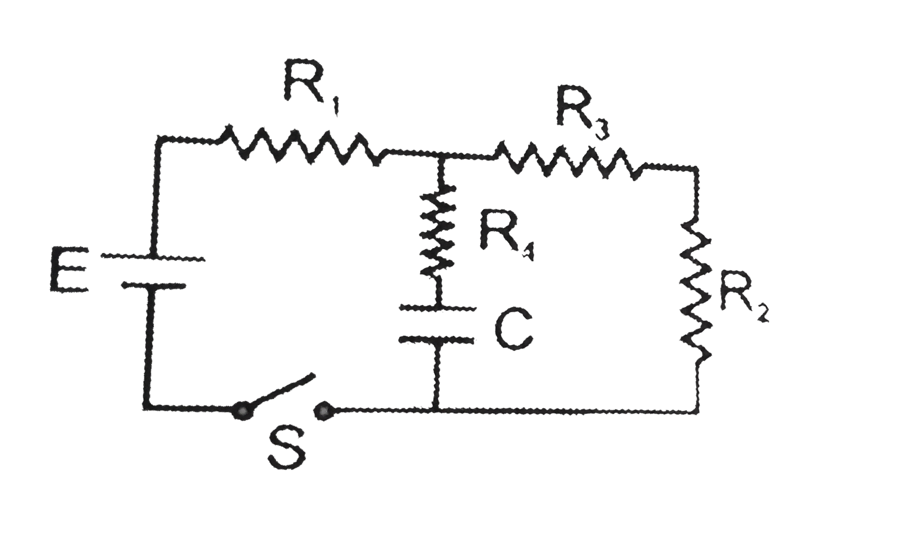
In the circuit shown in figure-3.240 switch S is closed at time t=0. find the current through different wires and charge stored on the capacitor at any time t.
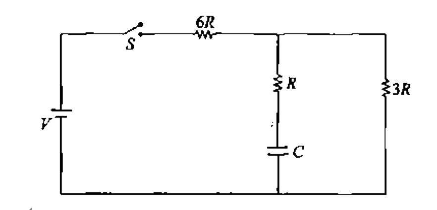
View SolutionIn the circuit shown in the figure, switch S is closed at time t=0. Select the correct statements.
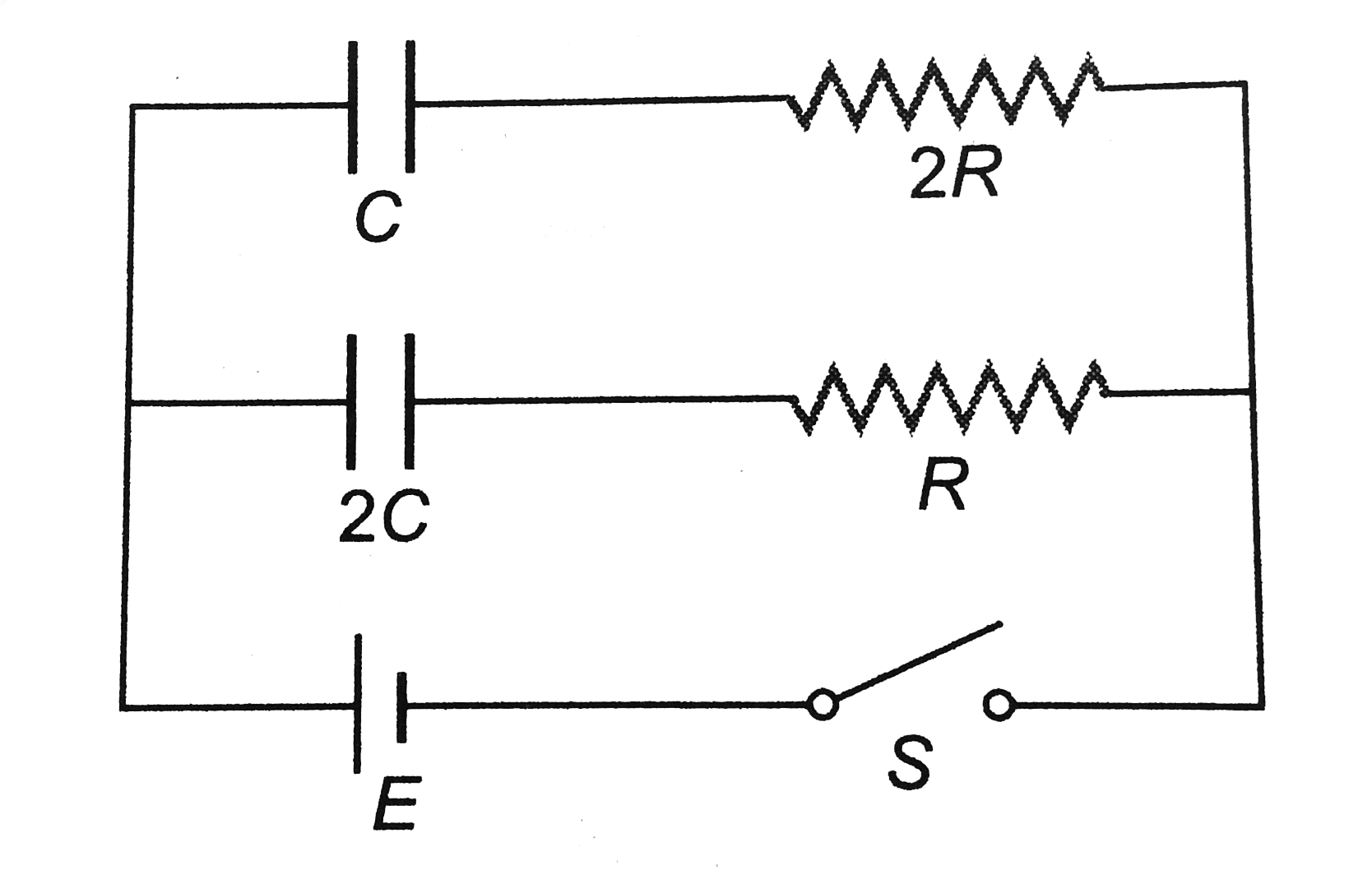
View SolutionIn the circuit shown in the figure, switch S is closed at time t=0. Select the correct statements.

View SolutionIn the circuit shown, switch S is closed at time t=0. Find the current through the inductor as a function of time t.
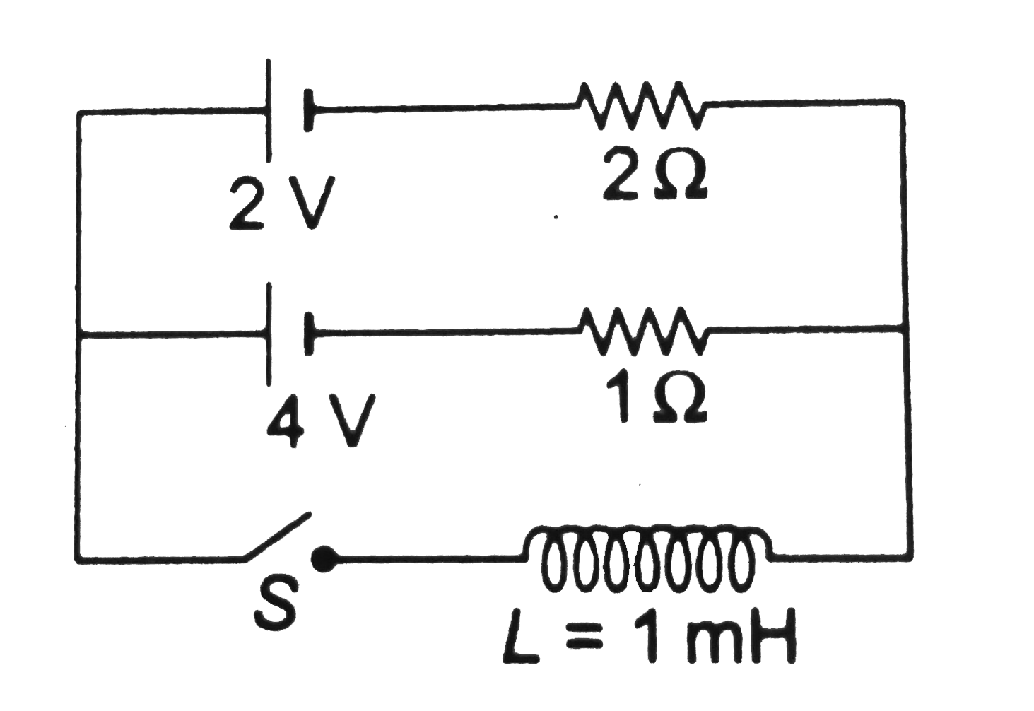
View SolutionIn the circuit shown in figure switch S is closed at time t=0
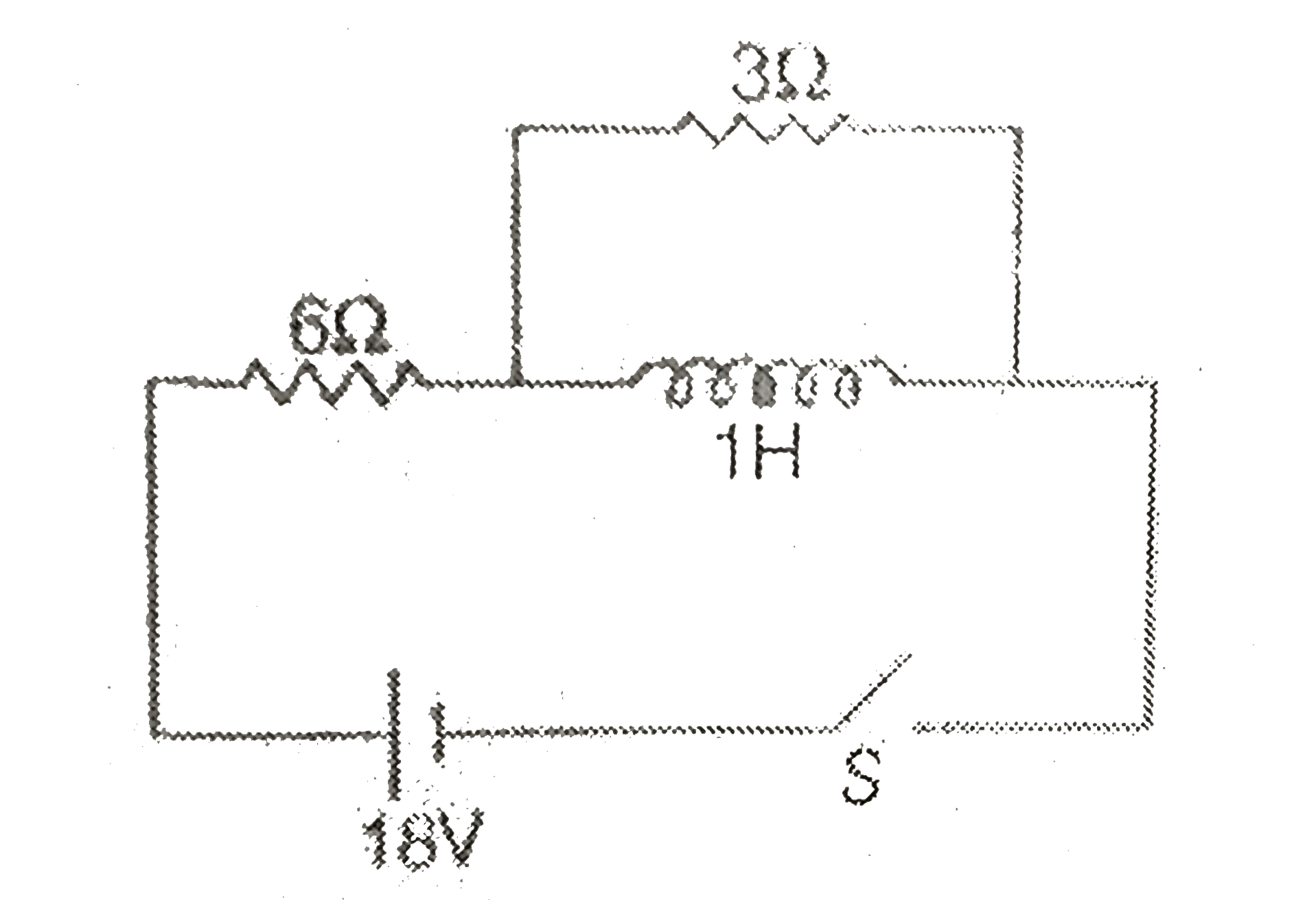
Current I from the battery at time t is given by
View SolutionIn the circuit shown in figure switch S is closed at time t=0
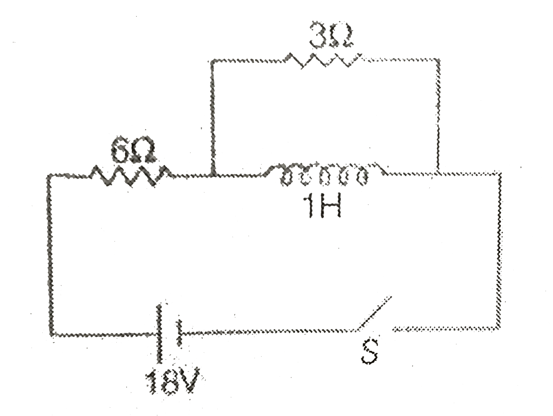
At what time current through 3Ω resistance and 1H inductor are equal?
View Solution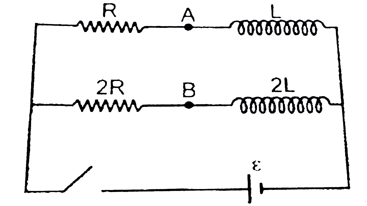
In given LR circuit the switch S is closed at time t=0 then
View SolutionIn the circuit shown, the switch 'S' is closed at t=0. Then the current through the battery steady state reached is
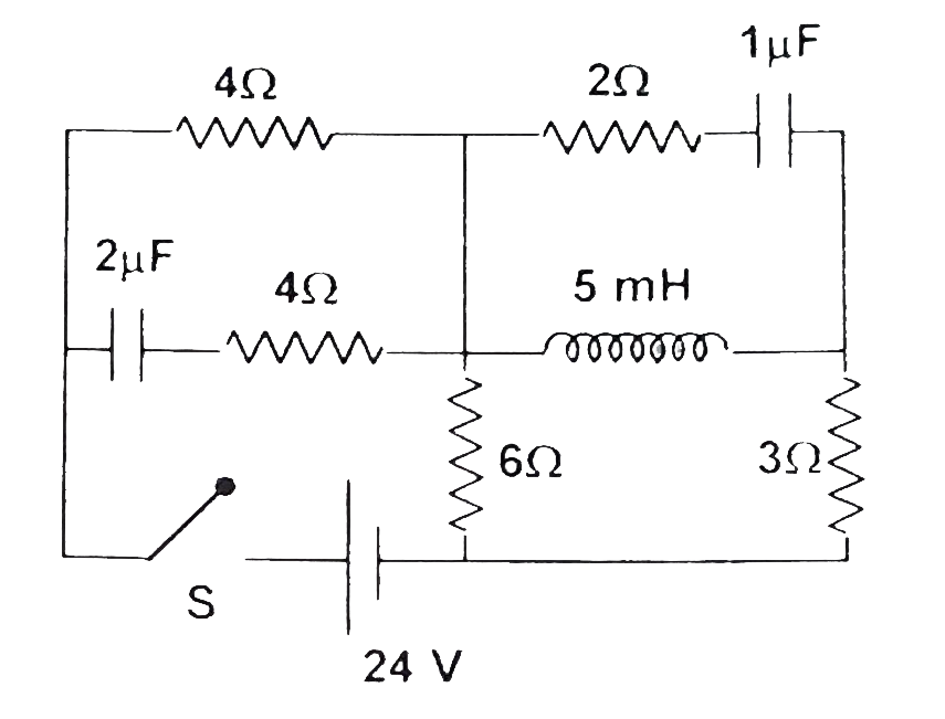
View SolutionSwitch S is cloesd in the circuit at time t=0. Find the current through the capacitor and the inductor at any time t
View SolutionIn the circuit shown in figure the switch S is closed at t = 0. A long time after closing the switch
View Solution
