In the accompanying diagram , if C1=3μF,C2=6μF,C3=9μF,C4=12μF,C5=15μFandC6=18μF , then the equivalent capacitor between the ends A and B is

1.22μF
5.16μF
2.25μF
2.51μF
The correct Answer is:D
Step by step video & image solution for In the accompanying diagram , if C_(1)=3muF,C_(2)=6muF,C_(3)=9muF,C_(4)=12muF,C_(5)=15muF and C_(6)=18muF , then the equivalent capacitor between the ends A and B is by Physics experts to help you in doubts & scoring excellent marks in Class 12 exams.
Updated on:21/07/2023Topper's Solved these Questions
- CAPACITORS BOOK - AAKASH SERIESCHAPTER - CAPACITORS EXERCISE - ADDITIONAL PRACTICE EXERCISE (LEVEL - II LECTURE SHEET (ADVANCED))(Straight Objective Type Questions)
9 Videos
- CAPACITORS BOOK - AAKASH SERIESCHAPTER - CAPACITORS EXERCISE - ADDITIONAL PRACTICE EXERCISE (LEVEL - II LECTURE SHEET (ADVANCED))(Matrix Matching Type Questions)
1 Videos
- CAPACITORS BOOK - AAKASH SERIESCHAPTER - CAPACITORS EXERCISE - PRACTICE SHEET (EXERCISE - IV) (LEVEL - II (ADVANCED) (More than one correct answer Type Questions)
4 Videos
- ATOMSBOOK - AAKASH SERIESCHAPTER - ATOMSEXERCISE - PRACTICE EXERCISE
21 Videos
- COMMUNICATION SYSTEM BOOK - AAKASH SERIESCHAPTER - COMMUNICATION SYSTEM EXERCISE - LECTURE SHEET (LEVEL - I) (MAIN) (EXERCISE - IV) (Straight Objective & More than one Correct Answer Type Questions)
20 Videos
Similar Questions
In, given C1=3μF,C2=5μF,C3=9μF, and C4=13μF. What is the potential differnce between points A and B?
 .
.
View SolutionIn the circuit shown C1=15μF,C2==30μF,C3=30μF,C4=30μF and C5=60μF. At steady state, the potential difference between points P and Q is 50 V. Calculate the potential difference across capacitor with capacitance C5
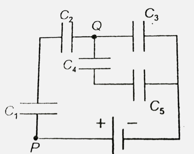
View SolutionThe equivalent capacity between A and B in the given circuit is (C1=4μF,C2=12μF,C3=8μF,C4=4μF,C5=8μF)

View SolutionIn the given network capacitance, C1=10μF,C2=5μF and C3=4μF. What is the resultant capacitance between A and B?
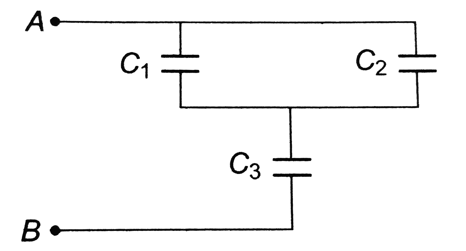
View SolutionIn the given network capacitance, C1=10μF,C2=5μF and C3=4μF. What is the resultant capacitance between A and B?

View SolutionIn the circuit shown in fig. R1=10Ω,R2=5Ω,C1=1μF,C2=2μF, and E =6V. Calculate the charge on each capactor in the stedy state.
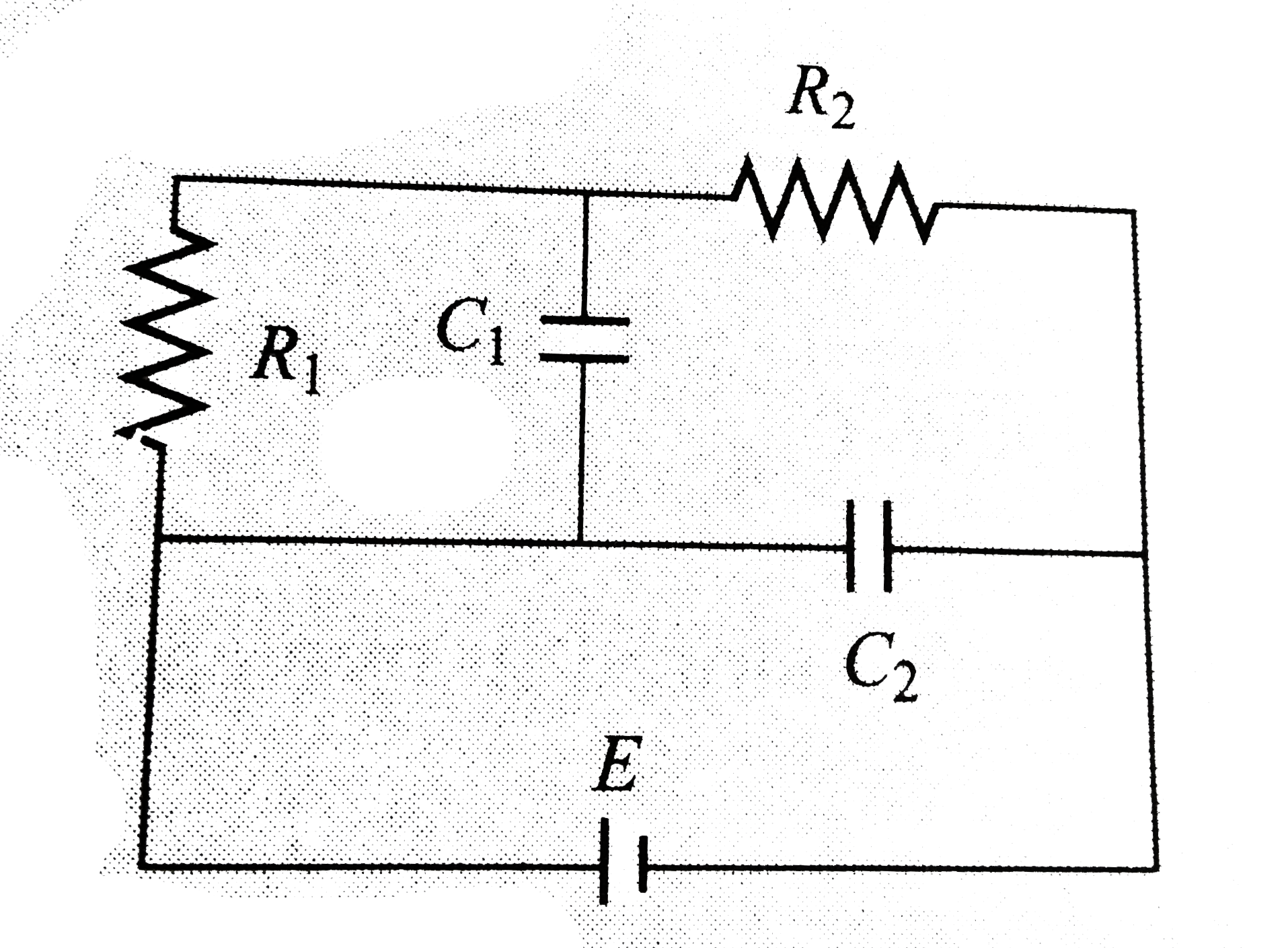
View SolutionIn the circuit shown in figure, R(1)=1Ω,R2=2Ω,C1=1μF,C2=2μF and E=6V. Calculate charge on each capacitor in steady state
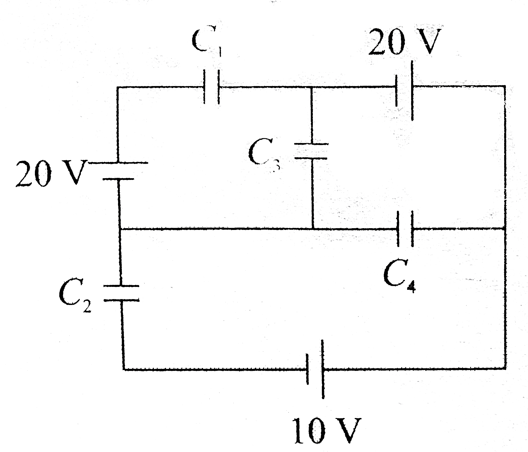
View SolutionFour capacitors C1=8μF,
C2=2μf,C3=6μF, and C4=6,μF are arranged as shown in. Find the charge on all the capacitors in the circuit.
 .
.
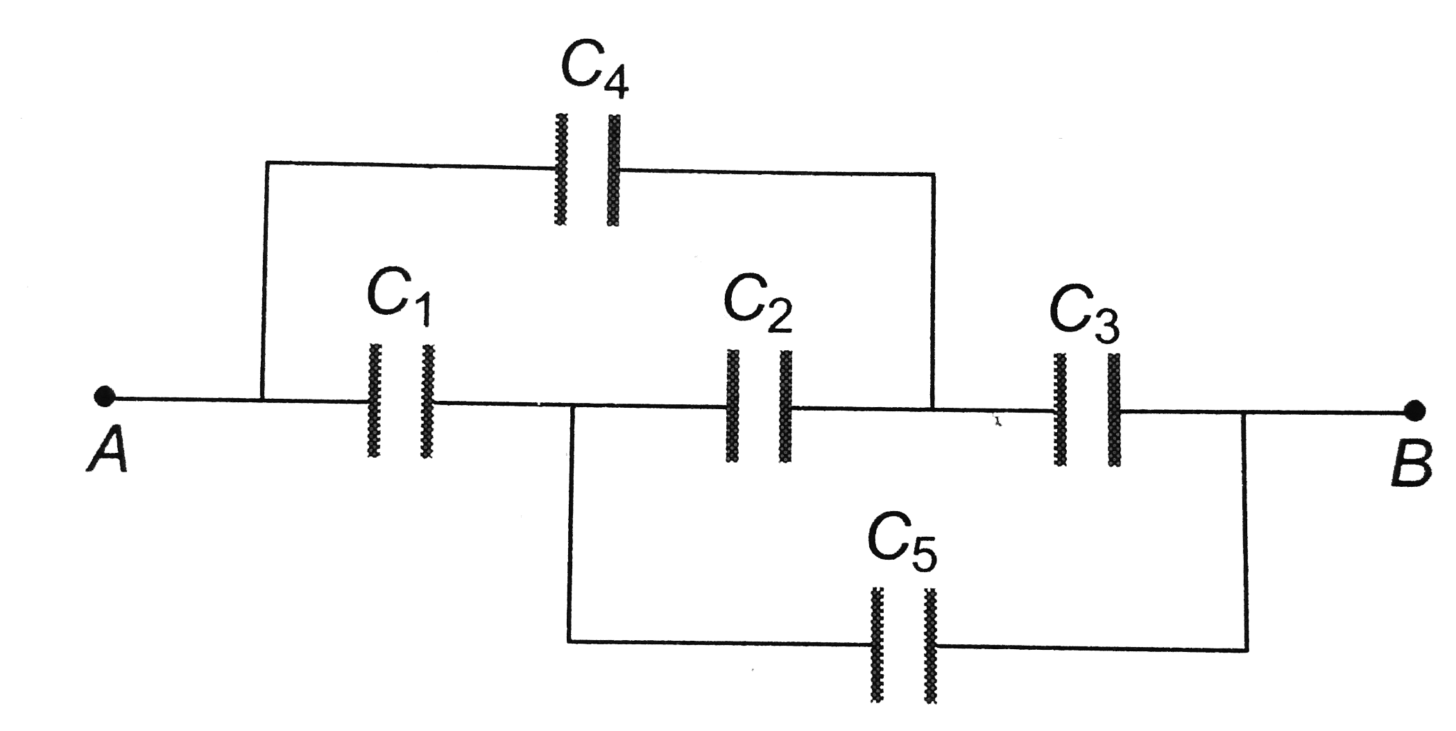
View SolutionIn the given figure the capacitors C1,C3,C4,C5 have a capaciance 4μF each if the capaitor C2 has a capacitance 10μF, then effective capacitance between A and B will be
View SolutionIn figure C1=C5=8.4μF and C2=C3=C4=4.2μF.The applied potential is Vab=220V
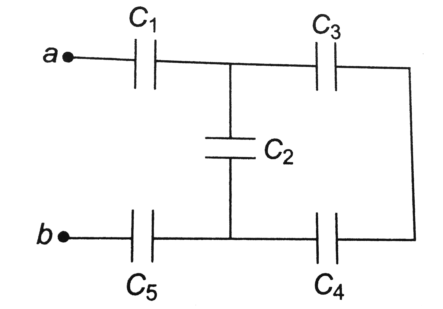
(a) What is the equivalent capacitance of the network between points a and b?
(b) Calculate the charge on each capacitor and the potential difference across each capacitor.
View Solution
