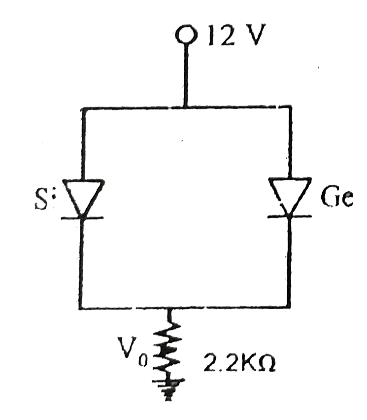
A circuit is arranged as shown in figure. The output voltage V0 is equal to ____________V.
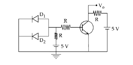
Step by step video & image solution for A circuit is arranged as shown in figure. The output voltage V_(0) is equal to ____________V. by Physics experts to help you in doubts & scoring excellent marks in Class 12 exams.
Updated on:21/07/2023Topper's Solved these Questions
- JEE MAINS 2021Book:JEE MAINS PREVIOUS YEARChapter:JEE MAINS 2021Exercise:Physics (Section A )
Explore 20 Videos
- JEE MAINS 2021Book:JEE MAINS PREVIOUS YEARChapter:JEE MAINS 2021Exercise:Physics (Section B )
Explore 10 Videos
- JEE MAINS 2021Book:JEE MAINS PREVIOUS YEARChapter:JEE MAINS 2021Exercise:Physics (Section A)
Explore 81 Videos
- JEE MAINS 2020Book:JEE MAINS PREVIOUS YEARChapter:JEE MAINS 2020Exercise:PHYSICS
Explore 246 Videos
- JEE MAINS 2022Book:JEE MAINS PREVIOUS YEARChapter:JEE MAINS 2022Exercise:PHYSICS (SECTION -B)
Explore 10 Videos
Similar Questions
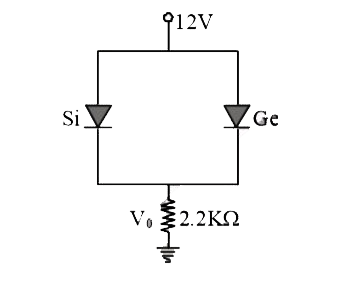
In the circuit shown in figure, Voltage V0 is–
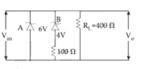
View SolutionTwo Zener diodes (A and B ) having breakdown voltage of 6 V and 4 V respecitvely , are connected as shown in the circuit below . The output voltage V0 variation with input voltage linearly increasing with time is given by :
(Vimput=0Vatt=0) ( figure are qualitative )
View Solution
Knowledge Check
In the circuit shown in figure the maximum output voltage V0 is
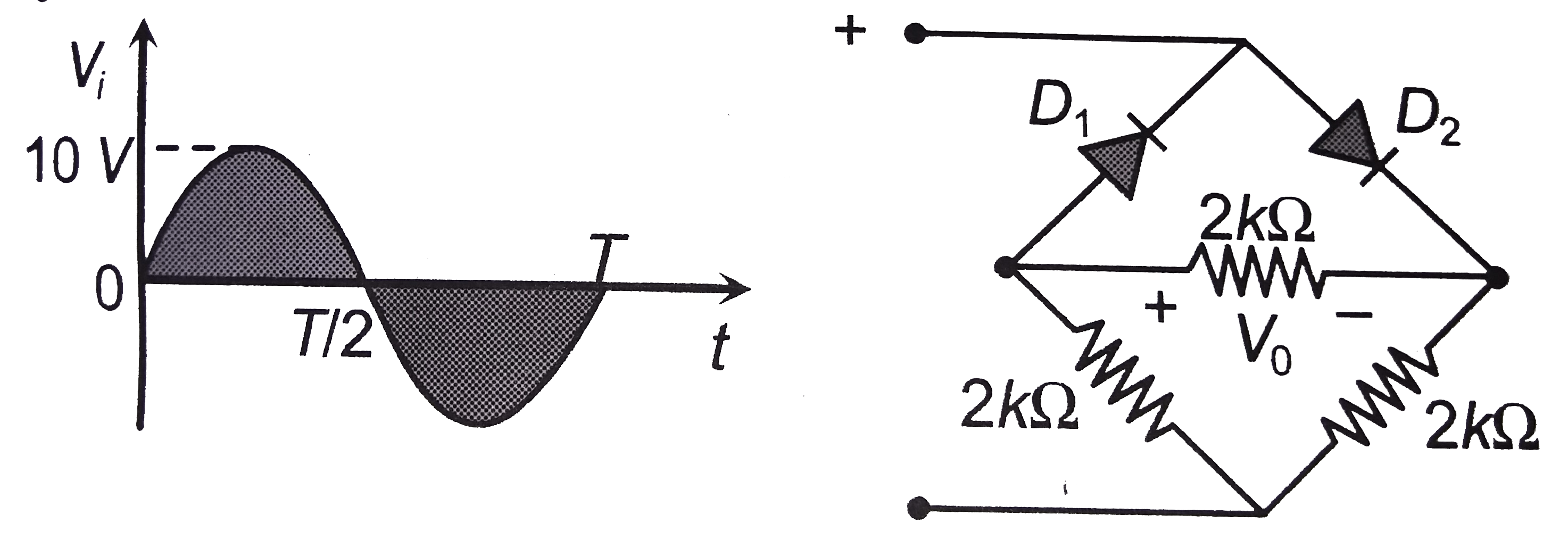 A0VB5VC10VD5√2V
In the circuit shown in figure, Voltage V0 is
 A11.7 voltB11.3 voltC0DNone
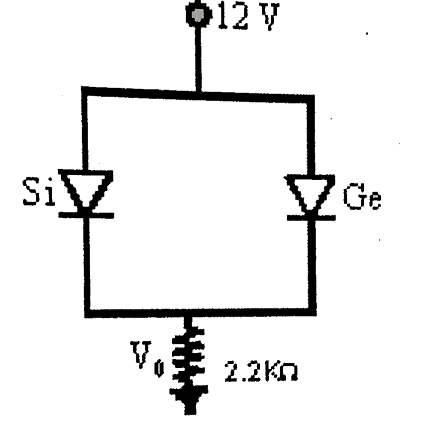
In the circuit shown infigure, voltage V0 is,A11.7 voltB11.3 voltC0DNone of these
In the circuit diagram of zener diode as shown in figure, when the value of V0 is 8 volt, the current through zener diode is i1 and when V0 is 16 volt, the corresponding current is i2. Find the value of (i2−i1). (Zener breakdown voltage V2=6V)
_2019_CBT6_E01_049_Q01.png)
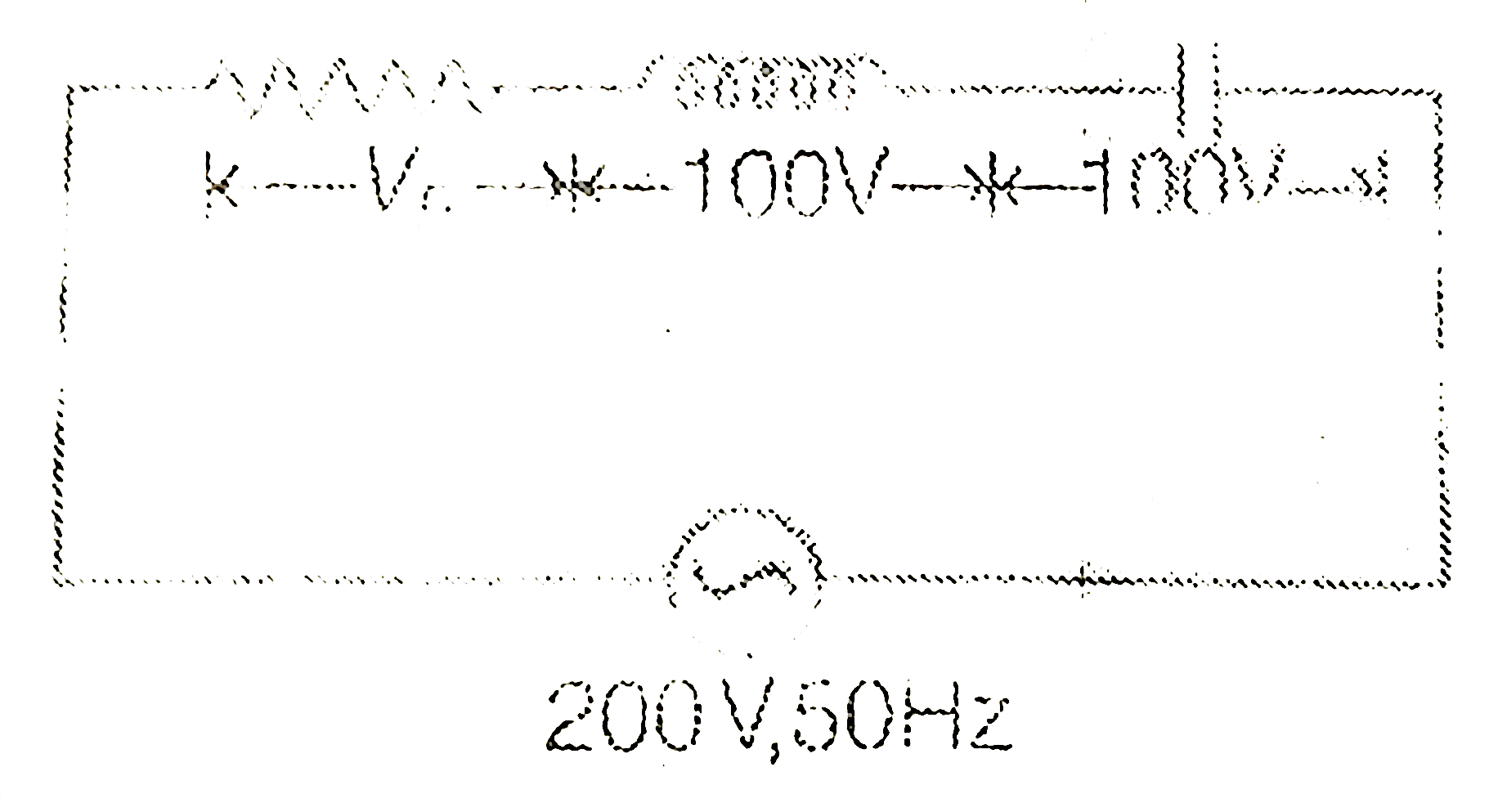
View SolutionIn the circuit shown in figure value of VR is
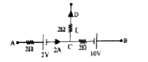
View SolutionA part of a circuit is shown in figure VR−VC is equal to 12 V. I1 is equal to
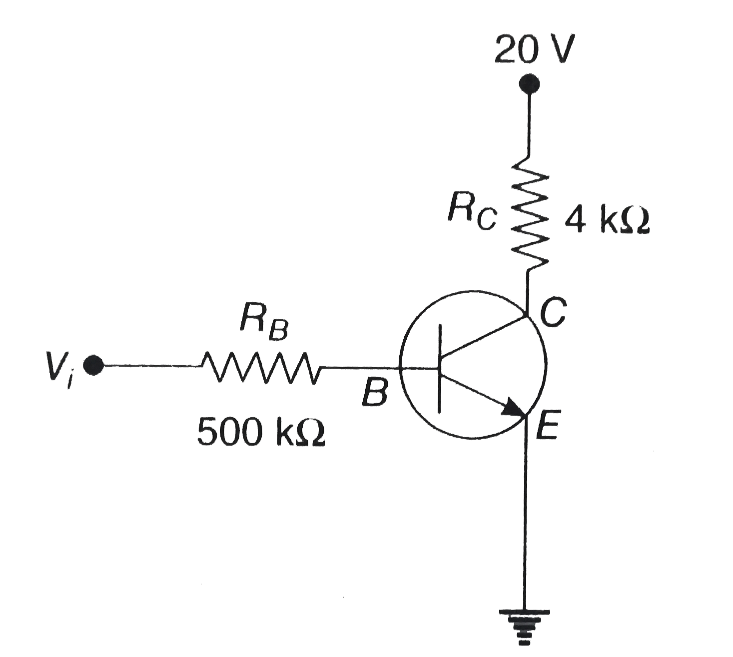
View SolutionIn the circuit shown in the figure, the input voltage Vi is 20V,VBE=0 and VCE=0. The values of IB,IC and β are given by:
View SolutionIn the circuit shown in figure , V must be
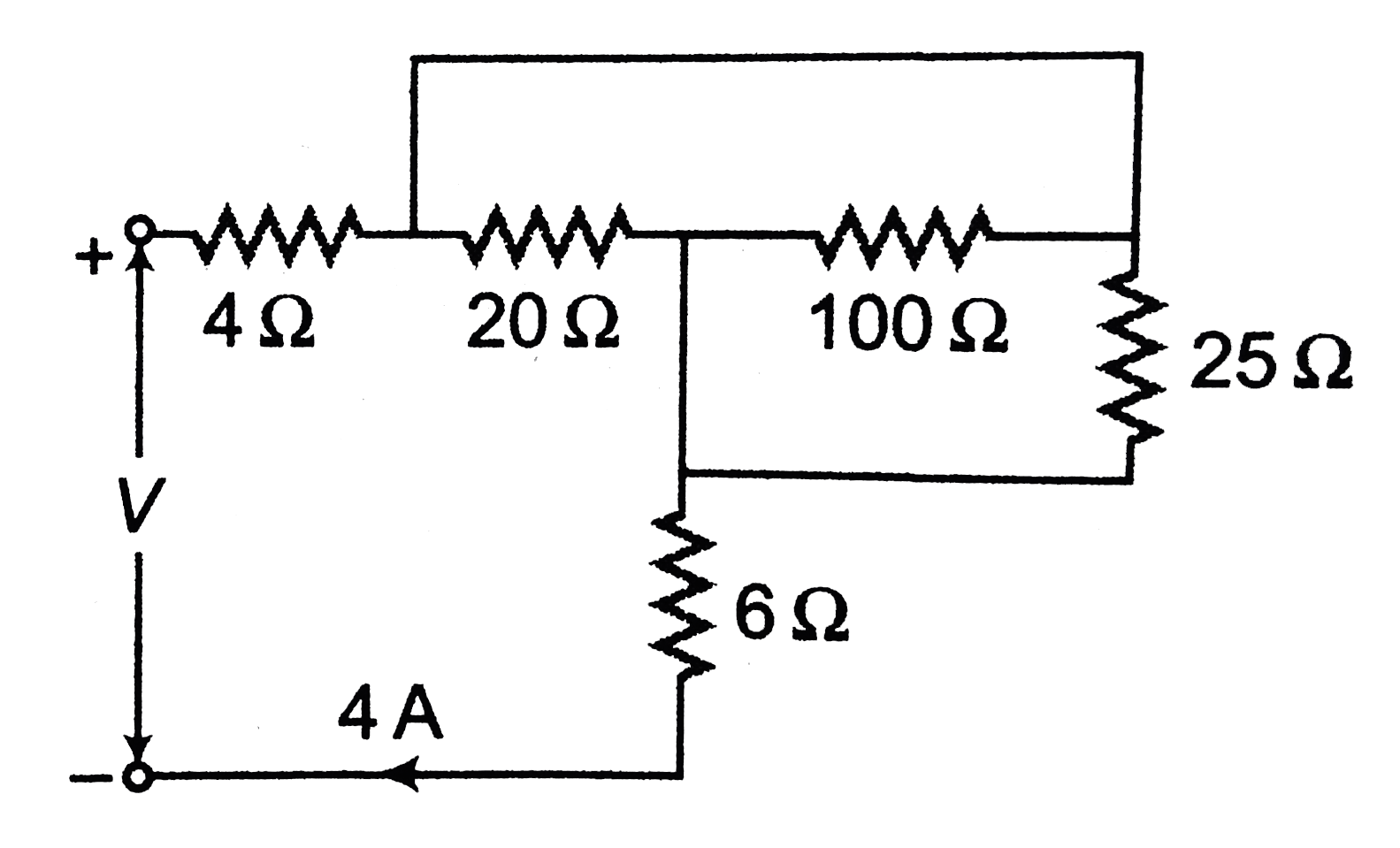
View Solution

