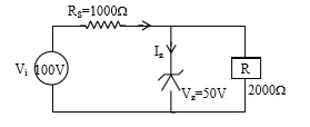
For the circuit shown below, calculate the value of Iz :
A
25 mA
B
0.15 A
C
0.1 A
D
0.05 A
Video Solution
|
Answer
Step by step video & image solution for For the circuit shown below, calculate the value of I_(z) : by Physics experts to help you in doubts & scoring excellent marks in Class 12 exams.
Updated on:21/07/2023
Related Playlists
- BOOK - JEE MAINS PREVIOUS YEARCHAPTER - JEE MAINS 2021EXERCISE - PHYSICS (SECTION-B)40videos
JEE MAINS 2021
- BOOK - JEE MAINS PREVIOUS YEARCHAPTER - JEE MAINS 2021EXERCISE - PHYSICS (SECTION - A)40videos
JEE MAINS 2021
- BOOK - JEE MAINS PREVIOUS YEARCHAPTER - JEE MAINS 2020EXERCISE - PHYSICS246videos
JEE MAINS 2020
- BOOK - JEE MAINS PREVIOUS YEARCHAPTER - JEE MAINS 2022EXERCISE - PHYSICS (SECTION -B)10videos
JEE MAINS 2022
Similar Practice Problems
- Question 1 - Select One
The circuit shown below acts as
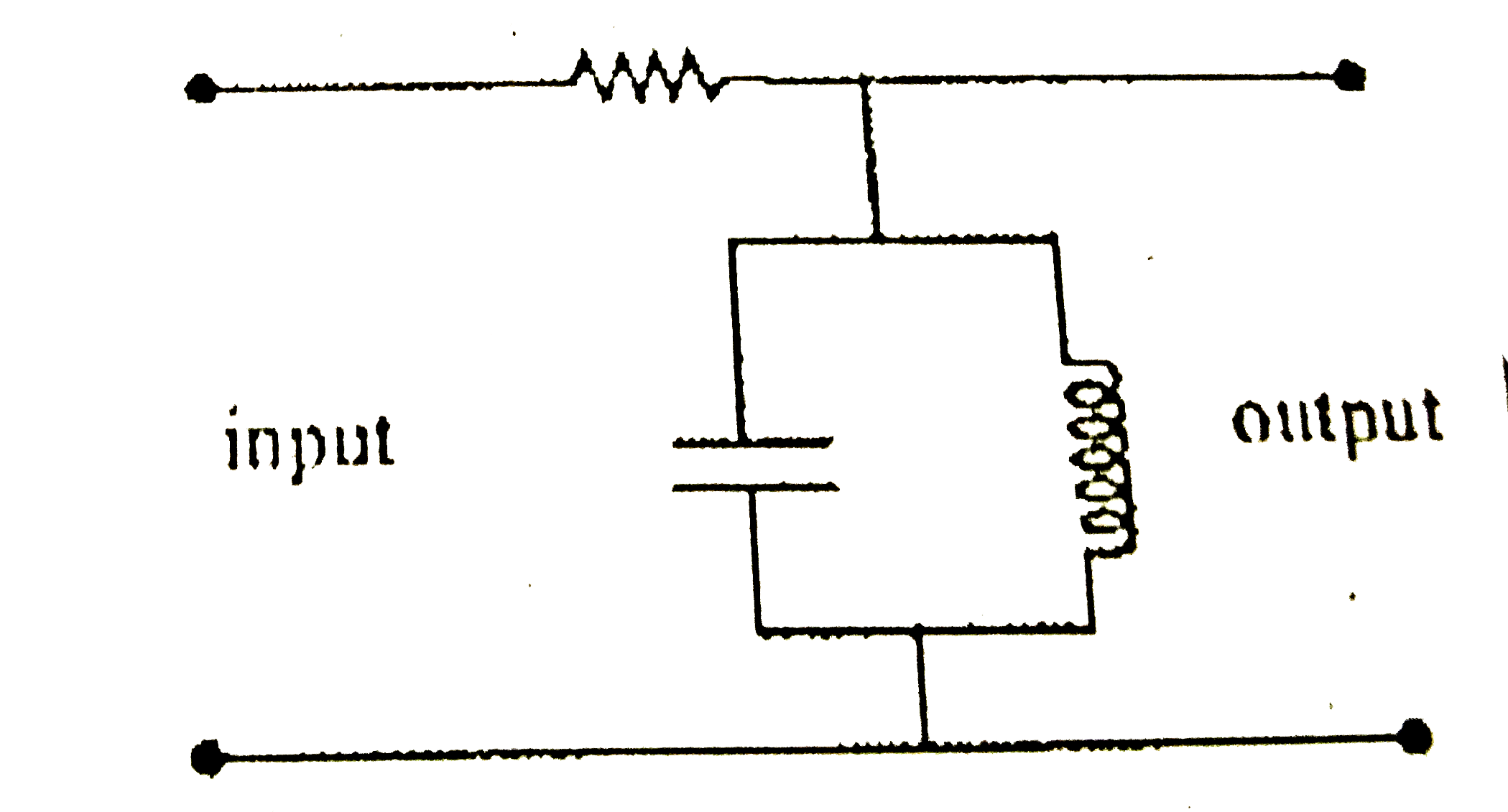 Atuned filterBlow pass filterChigh pass filterDrectifier
 - Question 1 - Select One
The circuit shown below acts as
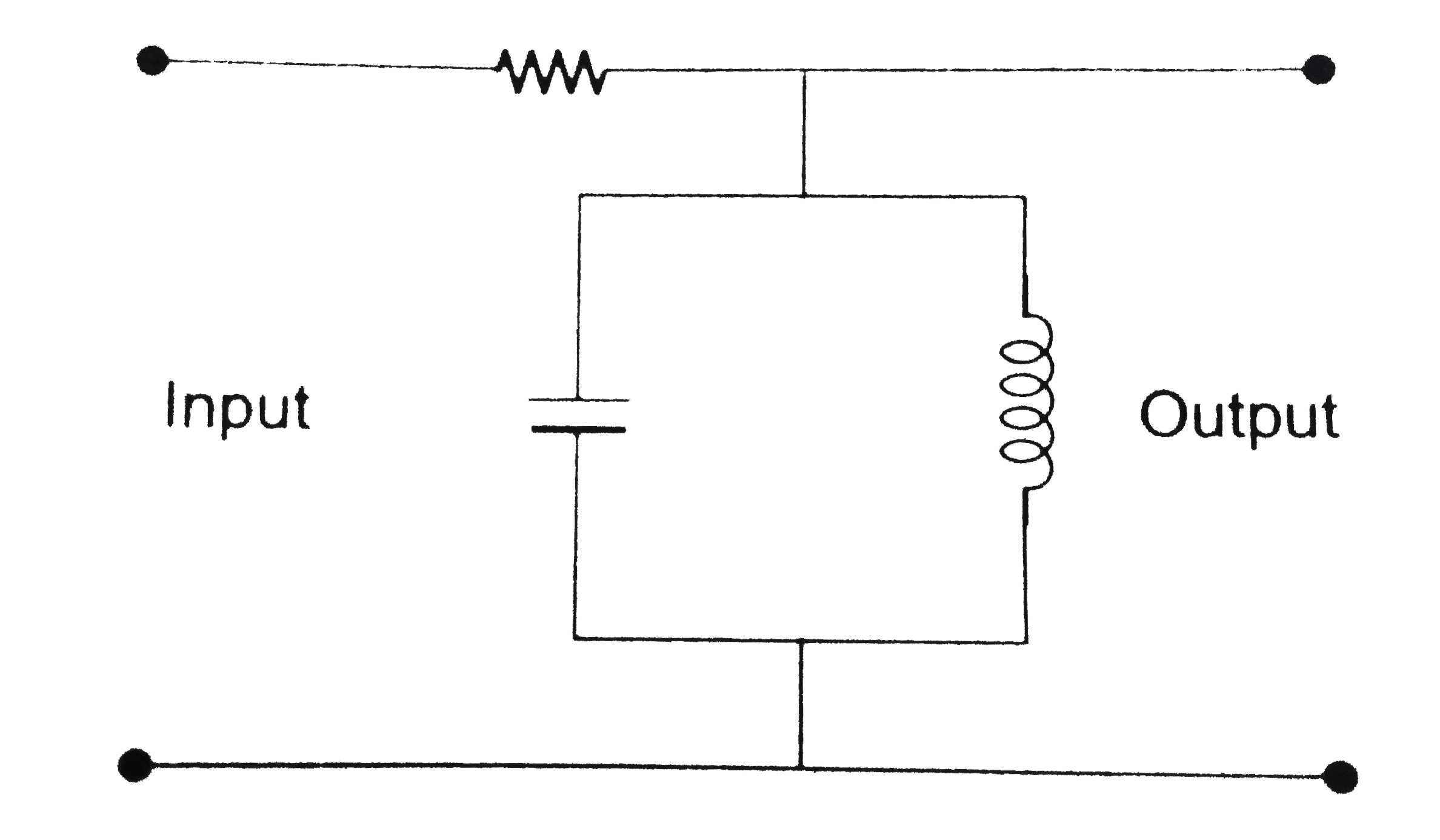 Ahigh pass filterBlow pass filterCtuned filterDrectifier
 - Question 1 - Select One
The circuit shown below will act as
 AAND gateBOR gateCNAND gateDXOR gate
 - Question 1 - Select One or More
A circuit is shown below.
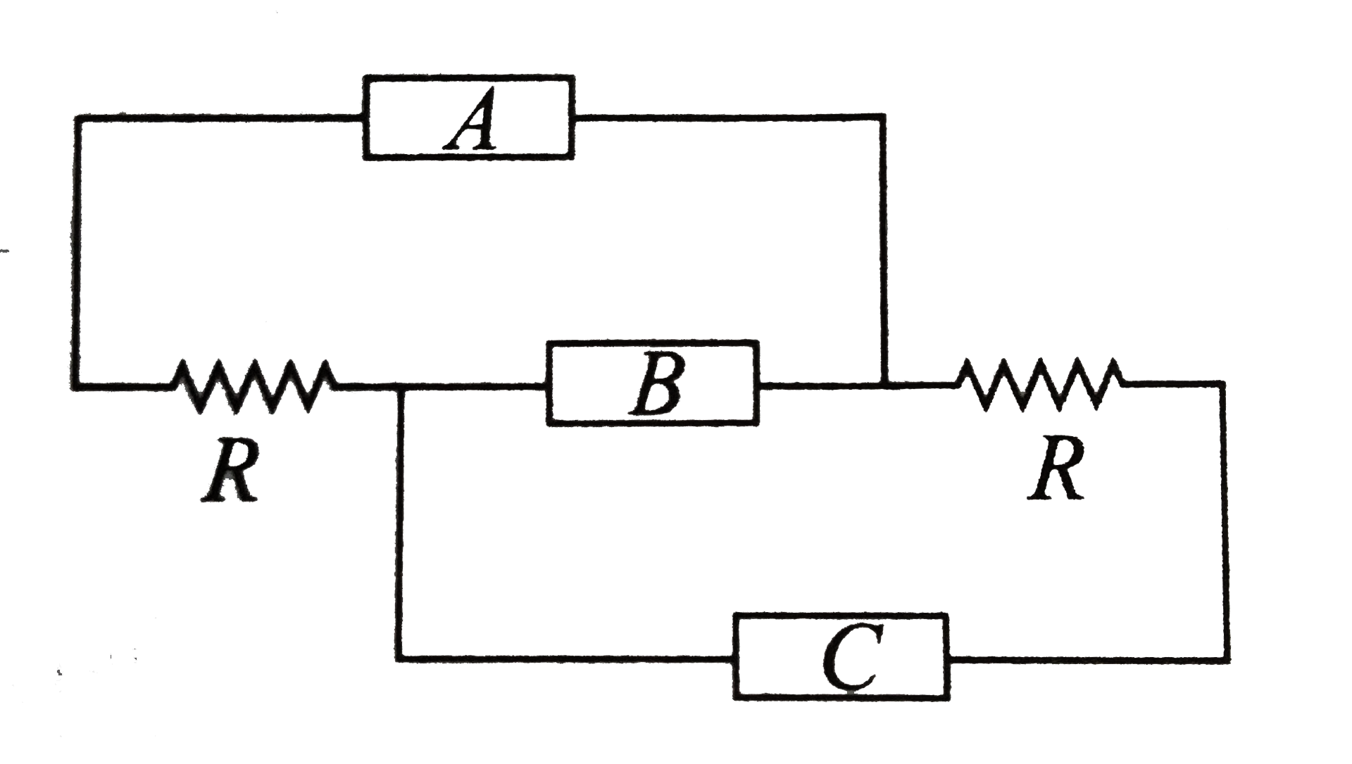 AIf A is an ideal ammeter, B an ideal battery of voltage V, and C an ideal voltmeter, the ratio reading of C/ reading of A is R.BIf A is a capacitor, B an ideal ammeter and C an ideal battery of voltage V, the potential difference across the capacitor is zero.CIf A is an ideal ammeter, B an ideal battery of voltage of V, and C an ideal voltmeter, the ratio reading of C/reading of A isR/2DIf A is a capacitor, B an ideal ammeter, and C an ideal battery of voltage V, the potential difference across the capacitor is 2 V.
 - Question 1 - Select One
Output of the circuit shown below will be
 Azero all the timesBlike half wave rectifier with positive cycles in outputClike half wave rectifier with nagative cycles in outputDlike that of a full wave rectifler
 - Question 1 - Select One
Carefully study the circuit diagram shown and calculate the value of x.
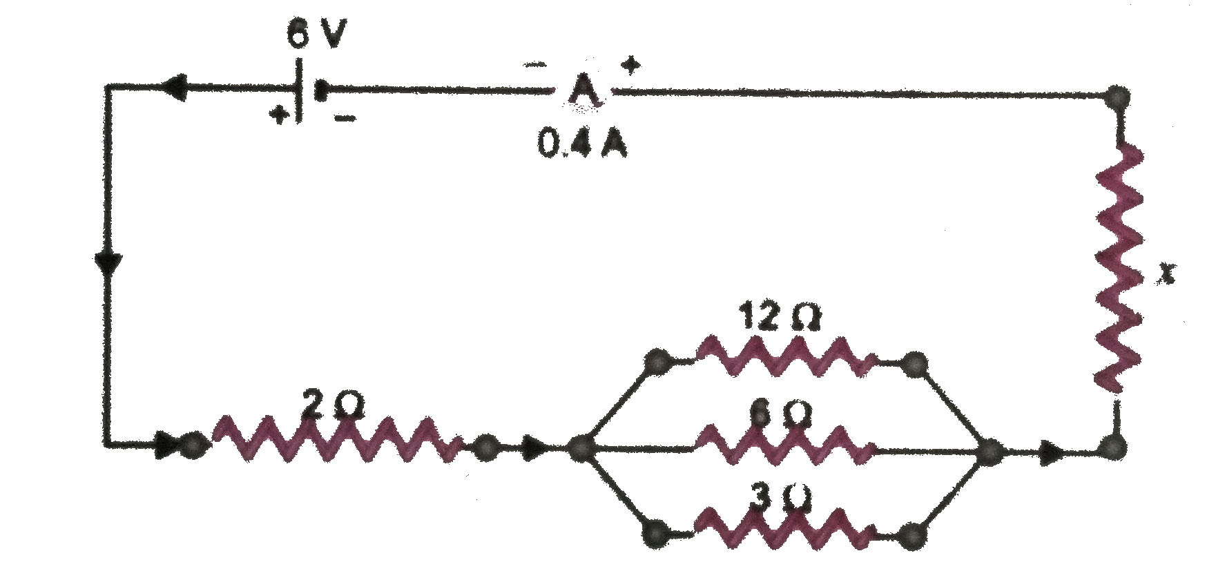 .A14.3 ohmB11.3 ohmC12 ohmD23.4 ohm
 - Question 1 - Select One
In the circuit shown below, V should be:
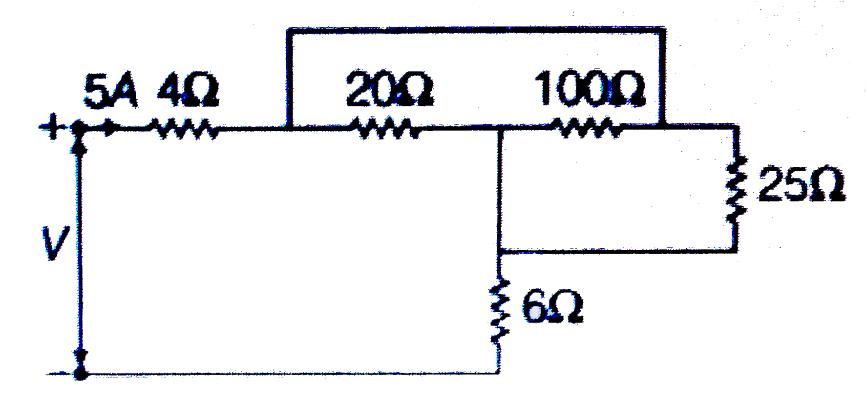 A50VB100VC75VD25V


