Is correct. In the circuit shown in the figure, the voltmeter reading would be.
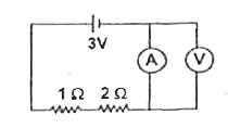
A
O volt.
B
0.5 volt.
C
1 volt.
D
2 volt.
Video Solution
Text Solution
The correct Answer is:A
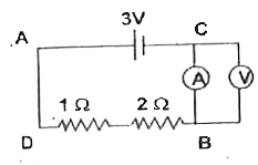
Current in the circuit I=33=1amp
potential drop across ABVAB=3×1=3V Hence no potential drop across voltmeter. Hence, (A) is correct
|
Updated on:21/07/2023
Similar Questions
Knowledge Check
- Question 1 - Select One
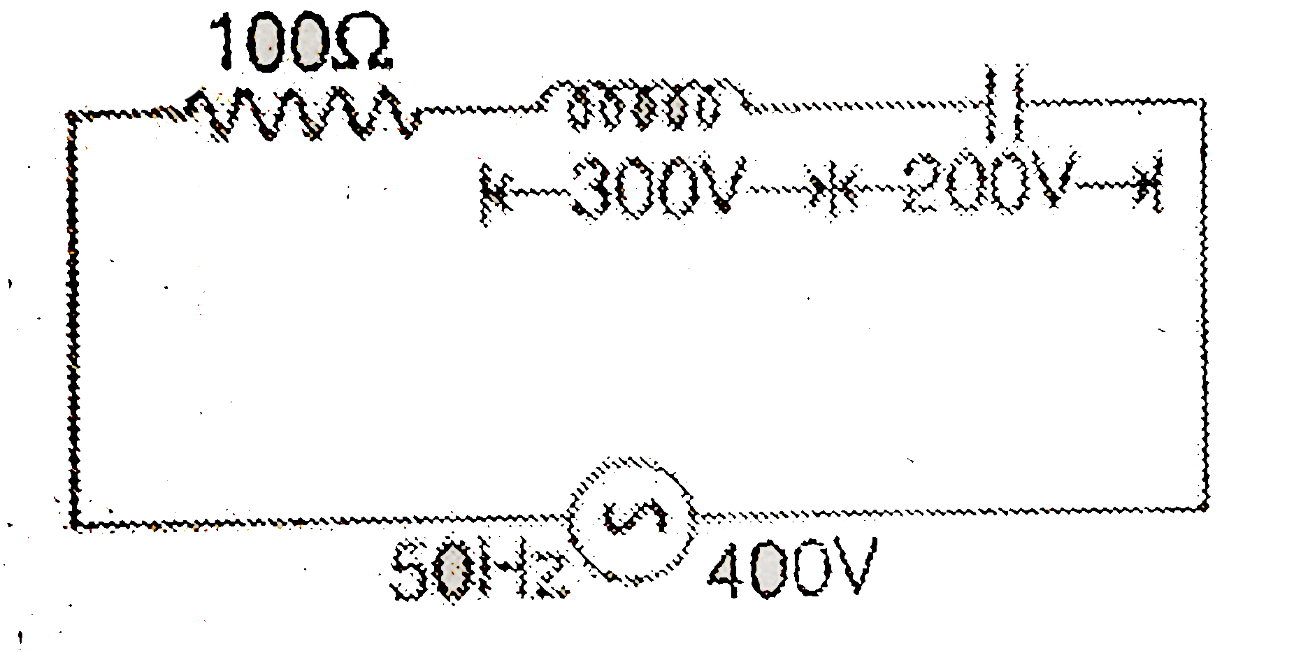
In the circuit shown in figure, what will be the reading of the voltmeter ?
 A300 VB900 VC200 VD400 V
 - Question 2 - Select One
State ohm's law.
In the circuit shown in figure, a voltmeter reads 30 volts when it is connected across 400 ohm resistance. Calculate what the same voltmeter will read when it is connected across the 300 ohm resistance.
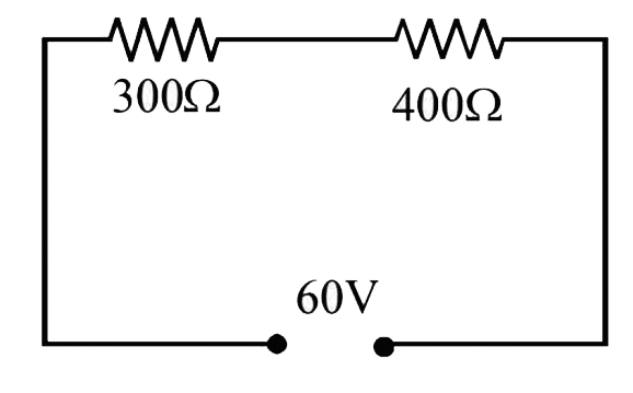 A30VB12.5VC15VD22.5V
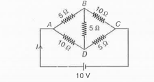
In the circuit shown in figure, the current / in circuit is
 View Solution
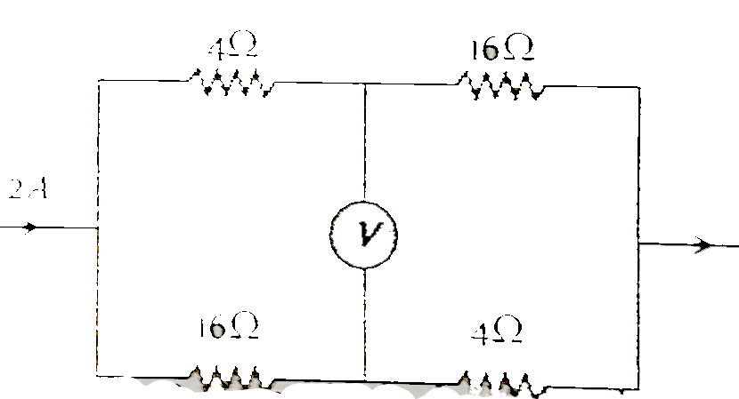
In the circuit shown below. The reading of the voltmeter V is
 View Solution
On closing the switch S in the circuit as shown in the figure, the reading of the galvanometer G
 View Solution
Consider the circuit shown in the figure, the cell is ideal. The readings of the ideal voltmeters V1 and V2 in volts are respectively.
 View Solution
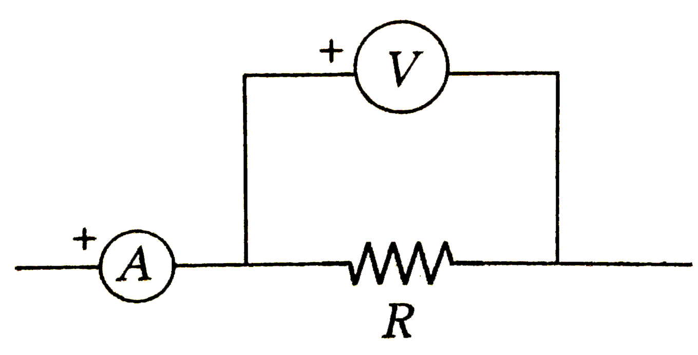
An ammeter A, a voltmeter V and a resistance R are connected as shown in the figure. If the voltmeter reading is 1.6V and the ammeter reading is 0.4A, then R is
 View Solution
In the circuit shown in figure current in the circuit is
 View Solution

