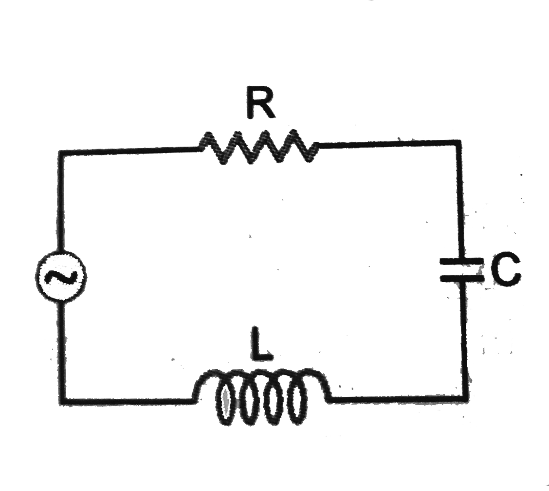
An LCR circuit has L = 10 mH, R=3Ω and C=1μF connected in series to a source of 15cosωt.volt. Calculate the current ampliuted and the average power dissipated per cycle at a frequency 10% lower than the resonance frequency.
To solve the problem step by step, we need to calculate the current amplitude and the average power dissipated per cycle in an LCR circuit.
Given Data:
- Inductance, L=10mH=10×10−3H
- Resistance, R=3Ω
- Capacitance, C=1μF=1×10⁻⁶F
- Voltage source, V(t)=15cos(ωt)V
- Frequency is 10% lower than the resonance frequency.
Step 1: Calculate the Resonant Frequency
The resonant frequency ωr for an LCR circuit is given by:
ωr=1√LC
Substituting the values:
ωr=1√10×10−3×1×10−6=1√10−9=104rad/s
Step 2: Calculate the Frequency 10% Lower than Resonance
The frequency ω′ that is 10% lower than the resonant frequency is:
ω′=0.9×ωr=0.9×104=9×10³rad/s
Step 3: Calculate Inductive Reactance XL
The inductive reactance XL is given by:
XL=ω′L
Substituting the values:
XL=9×103×10×10−3=90Ω
Step 4: Calculate Capacitive Reactance XC
The capacitive reactance XC is given by:
XC=1ω′C
Substituting the values:
XC=19×103×1×10−6=19×10−3≈111.11Ω
Step 5: Calculate the Impedance Z
The total impedance Z in the circuit is given by:
Z=√R2+(XL−XC)2
Substituting the values:
Z=√32+(90−111.11)2=√9+(−21.11)2=√9+445.6321≈√454.6321≈21.31Ω
Step 6: Calculate the Current Amplitude I0
The current amplitude I0 can be calculated using Ohm's law:
I0=V0Z
Where V0=15V:
I0=1521.31≈0.704A
Step 7: Calculate the Average Power Dissipated Pavg
The average power dissipated in the circuit is given by:
Pavg=VrmsIrmscosϕ
Where:
- Vrms=V0√2
- Irms=I0√2
- cosϕ=RZ
Calculating each component:
Vrms=15√2≈10.61V
Irms=0.704√2≈0.497A
cosϕ=321.31≈0.141
Now substituting into the power formula:
Pavg=10.61×0.497×0.141≈0.74W
Final Answers:
- Current Amplitude I0≈0.704A
- Average Power Dissipated Pavg≈0.74W
- Inductance, L=10mH=10×10−3H
- Resistance, R=3Ω
- Capacitance, C=1μF=1×10⁻⁶F
- Voltage source, V(t)=15cos(ωt)V
- Frequency is 10% lower than the resonance frequency.
The resonant frequency ωr for an LCR circuit is given by:
ωr=1√LC
Substituting the values:
ωr=1√10×10−3×1×10−6=1√10−9=104rad/s
The frequency ω′ that is 10% lower than the resonant frequency is:
ω′=0.9×ωr=0.9×104=9×10³rad/s
The inductive reactance XL is given by:
XL=ω′L
Substituting the values:
XL=9×103×10×10−3=90Ω
The capacitive reactance XC is given by:
XC=1ω′C
Substituting the values:
XC=19×103×1×10−6=19×10−3≈111.11Ω
The total impedance Z in the circuit is given by:
Z=√R2+(XL−XC)2
Substituting the values:
Z=√32+(90−111.11)2=√9+(−21.11)2=√9+445.6321≈√454.6321≈21.31Ω
The current amplitude I0 can be calculated using Ohm's law:
I0=V0Z
Where V0=15V:
I0=1521.31≈0.704A
The average power dissipated in the circuit is given by:
Pavg=VrmsIrmscosϕ
Where:
- Vrms=V0√2
- Irms=I0√2
- cosϕ=RZ
Vrms=15√2≈10.61V
Irms=0.704√2≈0.497A
cosϕ=321.31≈0.141
Pavg=10.61×0.497×0.141≈0.74W
- Current Amplitude I0≈0.704A
- Average Power Dissipated Pavg≈0.74W
Similar Questions
An LCR circuit has L=10mH,R=150Ω and C=1μF connacted in series to a source of 150√2cosωt volt. At a frequency that is 50% of the resonant frequency.calculate the average power (in watt) dissipated per cycle.
View SolutionAn AC circuit has R= 100Ω , C= 2μ and L= 80 mH, connected in series. The quality factor of the circuit is :
View Solution
Knowledge Check
A series LCR circuit has R=5Ω,L=40mH and C=1μF, the bandwidth of the circuit is
A10 HzB20 HzC30 HzD40 Hz
In an L C R circuit having L = 8 H, C = 0 5μF and R=100Ω in series, the resonance frequency in rad/s is
View SolutionA series LCR circuit with L=4.0H,C=100μF and R=60Ω is connected to a variable frequency 240 V source. Calculate
(i) angular frequency of the source which drives the circuit in resonance,
(ii) current at the resonating frequency,
(iii) rms potential drop across the inductance at resonance.
View SolutionFig. shows series LCR circuit with L=5.0H,C=80μF,R=40Ω connected to a variable frequency 240 V source. Calculate
(i) the angular frequency of the source which drives the circuit at resonance.
(ii) Current at the resonating frequency.
(iii) the rms pot. drop across the capacitor at resonance.

View SolutionIn a series RC circuit with an AC source, R=300Ω,C=25μF,ε0=50V and v=50πHz. Find the peak current and the average power dissipated in the circuit.
View SolutionIf resistance R =10Ω, inductance L = 2 mH and capacitance C=5μF are connected in series to an AC source of frequency 50 Hz, then at resonance the impedance of circuit is
View SolutionIf L=25mH,C=1mF and R=10Ω then R.M.S current across source is

View SolutionAn LCR series circuit with L=100mH,C=100μF,R=120Ω is connected to an AC source of emfε=(30V)sin(100s−1)t. Find the impedane, the peak current and the resonant frequency of the circuit.
View Solution

