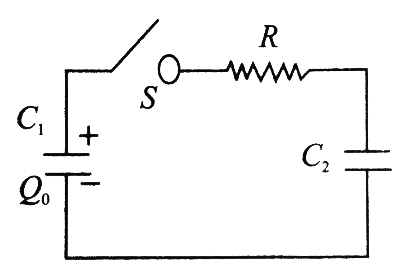
The capacitor C1 in the figure initially carries a charge q0. When the switch S1 and S2 are shut, capacitor C1 is connected in series to a resistor R and a second capacitor C2, which initially does not carry any charge.
If the heat lost in the resistor after a long time of closing the switch is q20C2kC1(C1+C2), then Find the value of k.
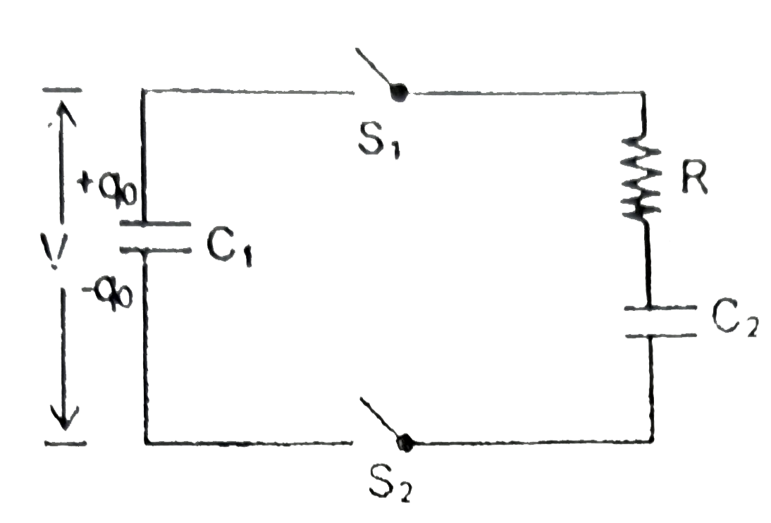
Electrostatic energy at t=0 is
U(0)=q202C1
Final energy =U(∞)=q202(C1+C2)
ΔU=U(0)−U(∞)=q20C22C1(C1+C2)
Similar Questions
The capacitor C1 in the flgure shown initially carries a charge q0. When the switches S1 and S2 are closed,capacitor C1 is connected in series to a resistor R and a second capacitor C2 which is initially uncharged.
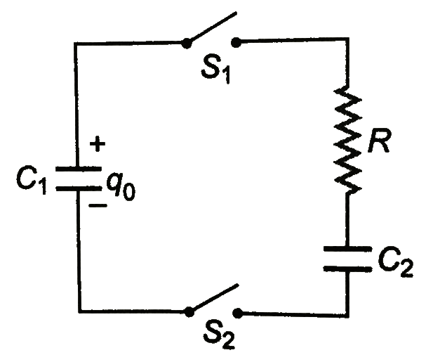
the total heat dissipated in the circuit during the discharging process of C1 is
View SolutionThe capacitor C1 in the figure shown initially carries a charge q0. When the switches S1 and S2 are closed,capacitor C1 is connected in series to a resistor R and a second capacitor C2 which is initially uncharged.
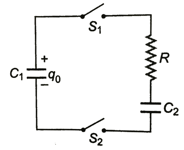
find the charge flown through wires as a function of time is
where C=C1C2C1+C2
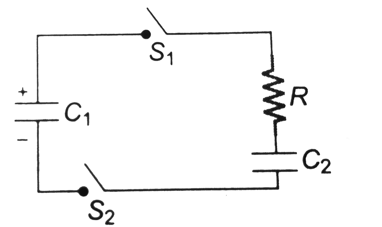
View SolutionThe capactor C1 in the figure initially carries a charge q0. When the i switch S1 and S2 are closed, capacitor C1 is connected to a resistor R and a second capacitor C2, which initially does not carry any charge.
(a) Find the charges deposited on the capacitors in steady state and the current through R as a function of time.
(b) What is heat lost in the resistor after a long time of closing the switch?
View SolutionIn the given figure switch is open initially and capacitor C2 is unchanged
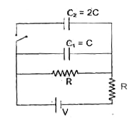
Charge on C2 just after closing the switch is
View SolutionFind the electric charge Q1 on plates of capacitor C_(1), shown in figure below :
View SolutionIn the circuit shown, the capacitor C1 is initially charged with charge q0. The switch S is closed at time t = 0 . The charge on C2 after time t is
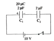
View SolutionWhen switch is closed , charges on C1andC2 are
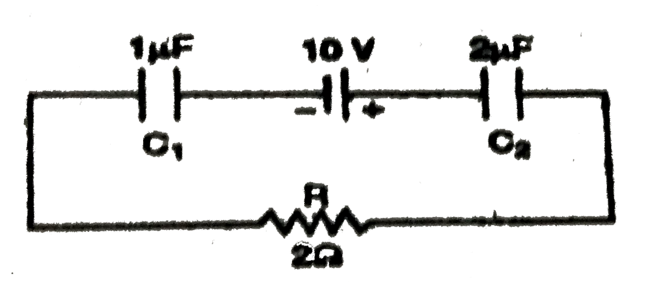
View SolutionA 10V battery is connected to two capacitors C1 and C2 and a resistor R. When the capacitors are fully charged, then the potential difference across the resistor will be
View SolutionIn the given figure switch is open initially and capacitor C2 is unchanged
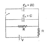
Potential difference on C1just after closing the switch is
View Solution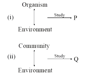
then P and Q are respectively called as.
View Solution