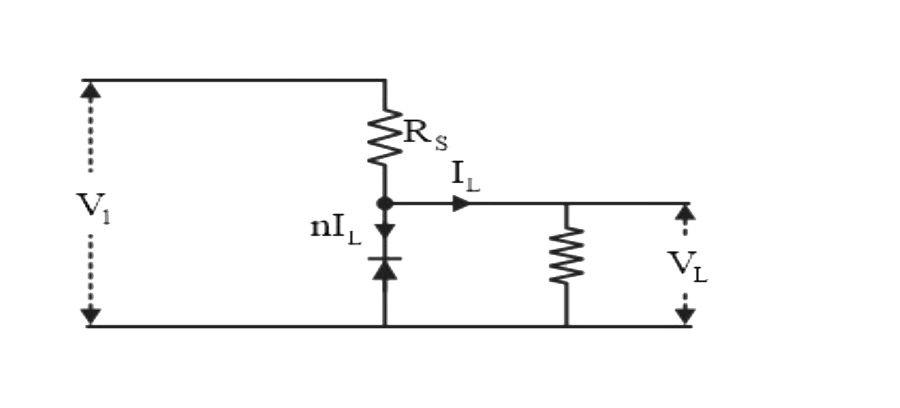
The value of the resistor , Rs needed in the DC voltage regulator circuit shown here equals :
(Vo−VL)/nIL
(Vi+V)/nIL
(V1+VL)/(n+1)IL
(Vi−VL)/(n+1)IL
The correct Answer is:D
_E01_502_S01.png)
Vi−VL=IRS
Vi−VL=(nIL+IL)RS
RS=V1=VL(n+1)IL
Topper's Solved these Questions
- SEMICONDUCTORSBook:ALLENChapter:SEMICONDUCTORSExercise:Part-3(Exercise-3)
Explore 27 Videos
- PHYSICAL WORLD, UNITS AND DIMENSIONS & ERRORS IN MEASUREMENT Book:ALLENChapter:PHYSICAL WORLD, UNITS AND DIMENSIONS & ERRORS IN MEASUREMENT Exercise:EXERCISE-IV
Explore 8 Videos
- WAVES AND OSCILLATIONSBook:ALLENChapter:WAVES AND OSCILLATIONSExercise:Part-1(Exercise-05)[B]
Explore 42 Videos
Similar Questions
Power factor of the circuit shown here is

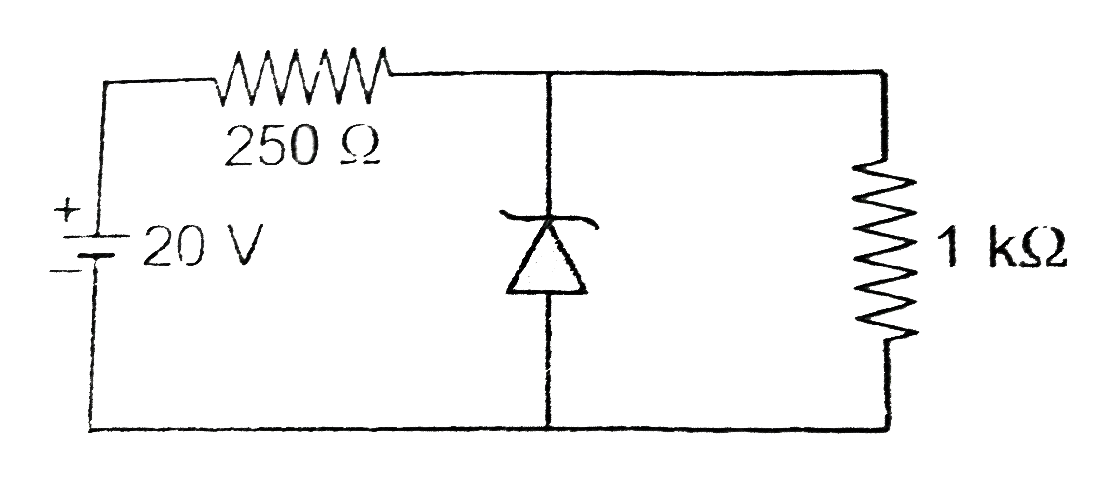
View SolutionA zener diode having breakdown voltage equal to 15V, is used in a voltage regulator circuit shown in figure. Find the current through the diode.
View SolutionIn the circuit shown here, what is the value of the unknown resistor R so that the total resistance of the circuit between points P and Q is also equal to R

View SolutionThe value of resistor R as shown in the given circuit is such that the power developed in the resistor R is maximum at steady state. The maximum charge stored on the capacitor is 100KμC. Find K.

View SolutionThe current in the resistor R3 in the circuit as shown in the figure is

View SolutionIn the figure there is a DC voltage regulator circuit, with a Zener breakdown voltage = 6V.If the unregulated input voltage varies between 10V to 16V,then what is the maximum Zener current?
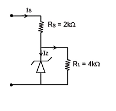
View SolutionIn the figure there is a DC voltage regulator circuit, with a Zener breakdown voltage = 6V.If the unregulated input voltage varies between 10V to 16V,then what is the maximum Zener current?

View SolutionThe circuit shown here is logically equivalent to :-
_E01_424_Q01.png)
View SolutionThe total power dissipated in watts in the circuit shown here is
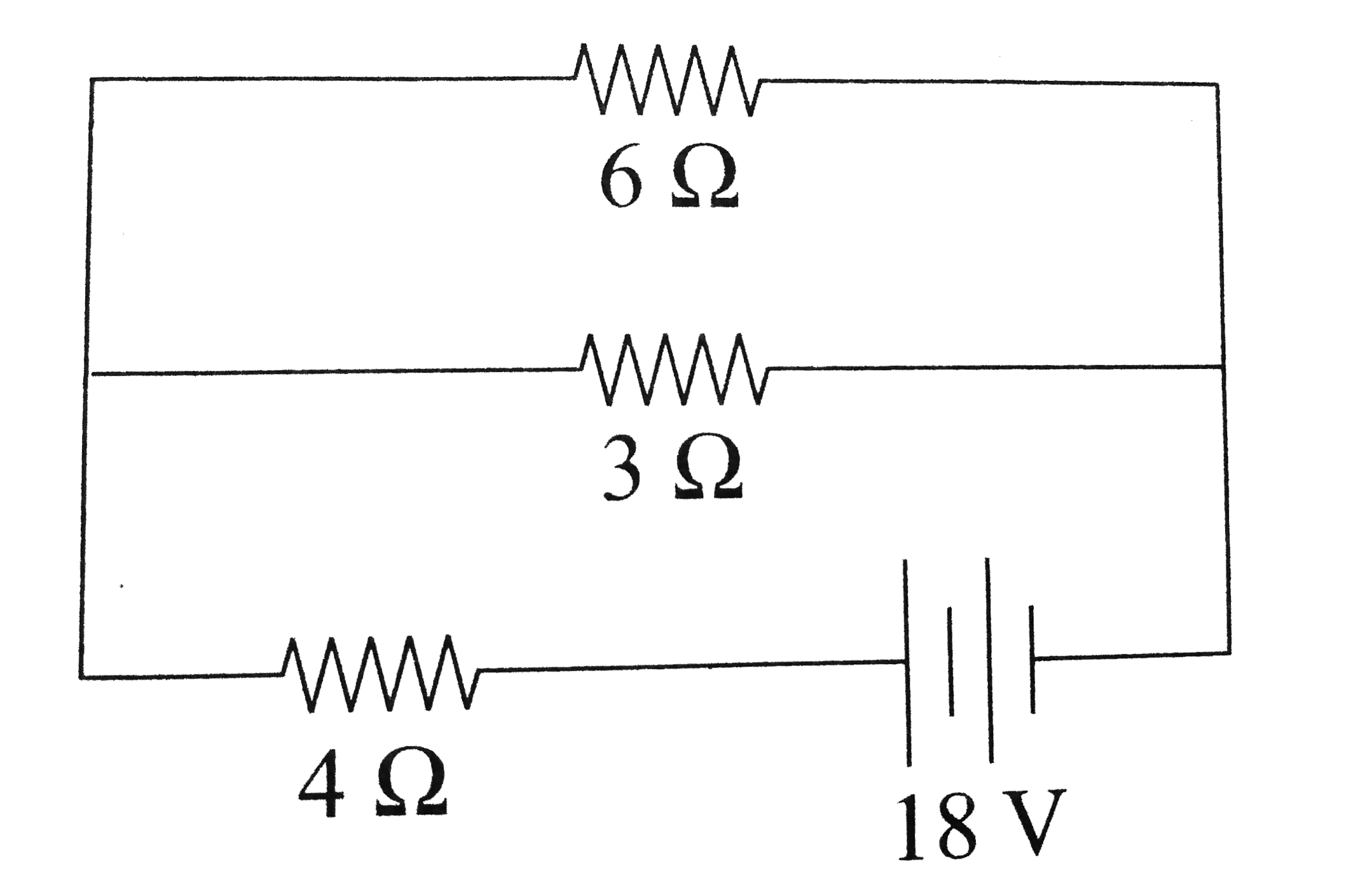
View SolutionIn the circuit shown in figure value of VR is
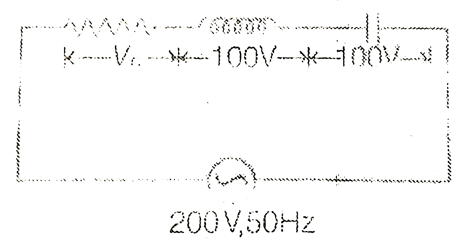
View Solution