Draw the logic symbol of OR gate. Write its truth table. Explain how this gate can be realized in actual practice by using junction diodes.Solution in Punjabi
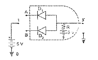
In practice , the AND gate is realised with the help of the electrons circuit using two diodes and as show in Fig. The two diodes play the roles of the switches A and B as explained below .

(a) A = 0 and B = 0 . Both the diodes and get forward biased and hence condcut . The output y will be the voltage drop acrooss or . Since diodes are ideal , no voltage drop occurs across the diodes . Hence , the output y is 0.
(b) A =1 and B = 0 . The diode will conduct and diode will remain idle . Now , output y is voltage across and hence it is 0.
(c) A = 0 and B = I . The diode will conduct , while will not conduct . Now , output y is voltage across , which is 0.
(d) A =1 and B =1 . Both the diodes will not conduct . The output y will equal battery voltage 5 V i.e., equal to 1.
These result in the four case are same as listed in Table 3.03 in the form of truth table of the AND gate .
Topper's Solved these Questions
- DIGITAL ELECTRONICS Book:BETTER CHOICE PUBLICATIONChapter:DIGITAL ELECTRONICS Exercise:SHORT ANSWER TYPE QUESTIONS
Explore 24 Videos
- DIFFRACTION OF LIGHTBook:BETTER CHOICE PUBLICATIONChapter:DIFFRACTION OF LIGHTExercise:Numberical Problem
Explore 1 Video
- DIPERSION OF LIGHTBook:BETTER CHOICE PUBLICATIONChapter:DIPERSION OF LIGHTExercise:MOST EXPECTED QUESTIONS
Explore 5 Videos
Similar Questions
Draw the logic symbol for 'OR' logic gate and write its truth tale .
View SolutionA concave lens of focal length 15cm forms an image 10 cm from the lens. How far is the object placed from the lens? Draw ray diagram.
View SolutionWhat do you mean by dispersion of light?
View SolutionAND गेट के लिये लॉजिक प्रतीक , सत्यता सारणी बनाइए तथा बूलियन व्यंजक लीखिए एवं बताइये कि इसे व्यवहार में दो p-n सन्धि डायोडो को प्रयुक्त करके किस प्रकार प्राप्त किया जा सकता है ?
View SolutionNOT गेट के लिये लॉजिक प्रतीक , सत्यता सारणी बनाइए तथा बूलियन व्यंजक दीजिए । परिपथ आरेख के साथ समझाइए कि यह गेट किस प्रकार प्राप्त किया जा सकता है ?
View SolutionNOT गेट के लिये लॉजिक प्रतीक , सत्यता सारणी बनाइए तथा बूलियन व्यंजक लीखिए तथा बताइये कि व्यवहार में यह गेट किस प्रकार प्रयुक्त होता है ?
View SolutionDraw an OR gate using two diode and explain its operation. Write the truth table and logic symbol of OR gate.
View SolutionOR गेट के लिए लॉजिक प्रतिक और सत्यमान सारणी लिखिए | व्याख्या कीजिए की दो डायोडों का उपयोग करते हुए यह व्यवहार में किस प्रकार प्राप्त किया जाता है ?
View SolutionWrite down the truth table of AND gate and also draw its logic symbol.
View SolutionHow ‘NAND’logic gate is obtained from basic gates ? Draw its logic symbol and write its truth table.
View SolutionDraw the logic symbol of AND gate.Write its truthtable also. How can one realise such a gate in actual practice by using junctions diodes ?
View SolutionDraw the logic symbol of NOT gate. Write. its truth table. Explain, how this gate can be realized in actual practice by using transistor
View SolutionDraw the logic symbol of OR gate. Write its truth table. Explain how this gate can be realized in actual practice by using junction diodes.
View Solution