Complete the drawing shown in Fig 12.14 to indicate where the free ends of the two wires should be joined to make the bulb glow.
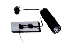
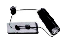
Earlier, the connection is not complete as one of the end of the cell is not connected to the switch and hence the bulb. Thus, there will be no flow of current in the circuit.
To complete the circuit, one of the end of the cell must be connected to the switch and then to the bulb. After this, bulb will start glowing as shown in the figure
Topper's Solved these Questions
Similar Questions
Complete the drawing shown in Fig 12.14 to indicate where the free ends of the two wires should be joined to make the bulb glow.

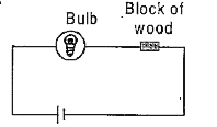
View SolutionLook at the circuit shown here
What should be done to make the bulb glow?
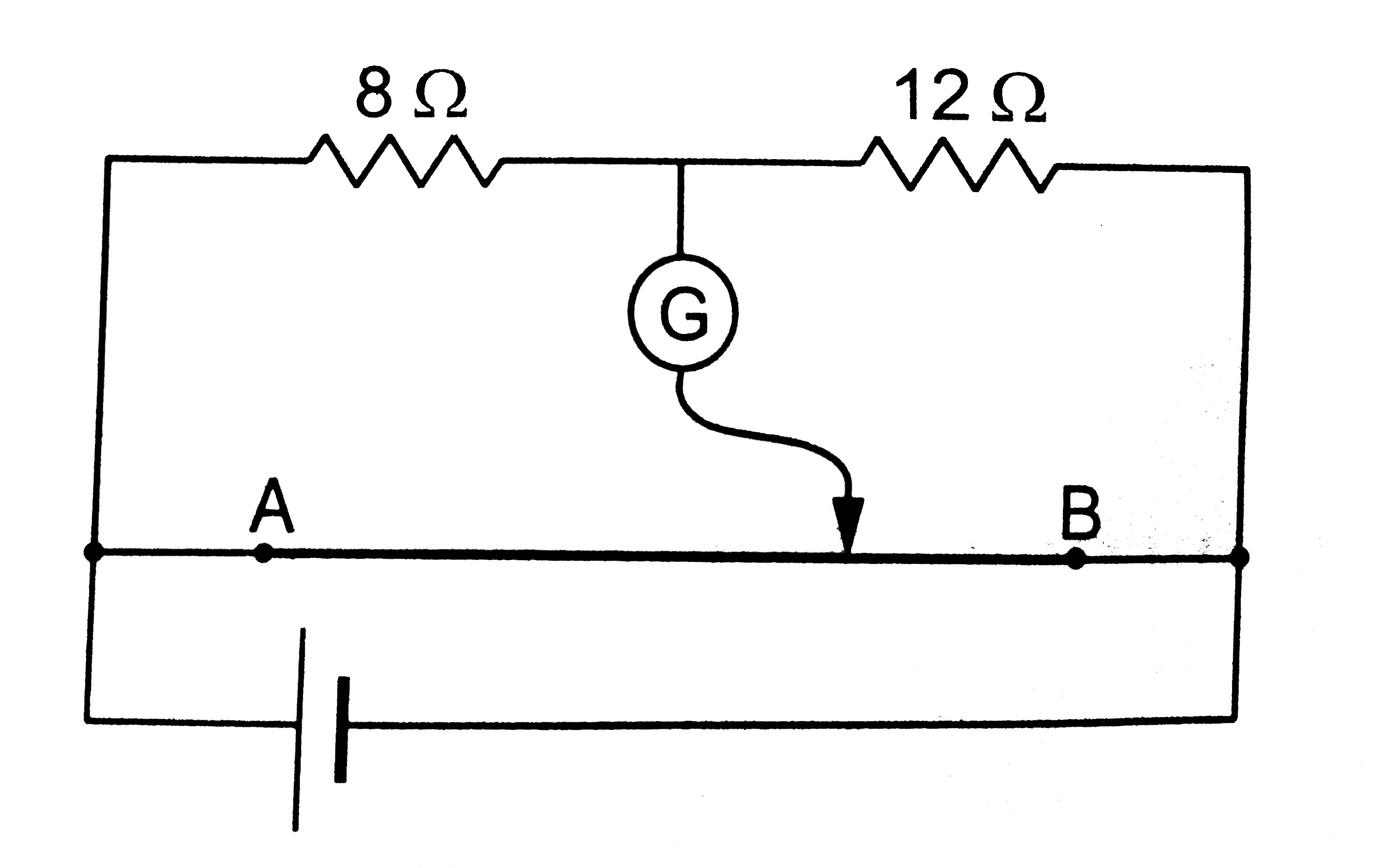
View SolutionThe potentiometer wire AB shown in figure is 40cm long. Where the free end of the galvanometer should be connected on AB so that the galvanometer may show zero deflection?
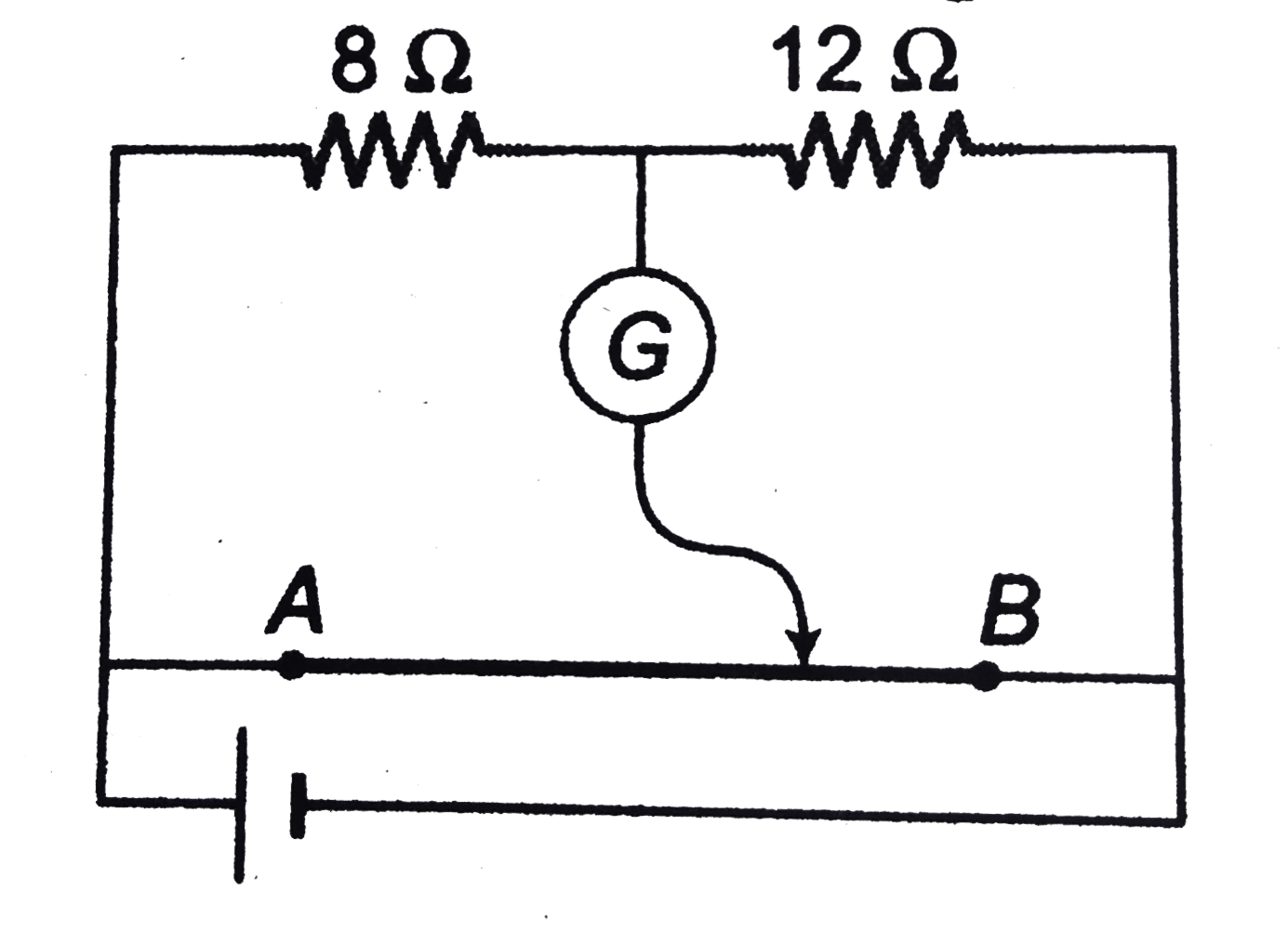
View SolutionThe potentiometer wire AB shown in figure is 40 cm long. Where should the free end of the galvanometer be connected on AB so that the galvanometer may show zero deflection?
View Solution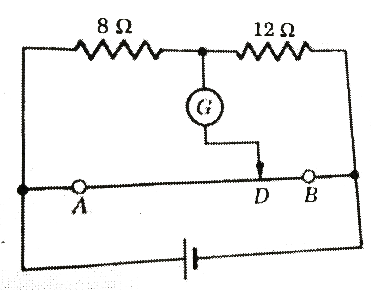
The potentiometer wire AB shown in figure. Is 40 cm long. Where should the free end of the galvanometer be connected on AB so that the galvanometer may show zero deflection?
View SolutionVarious parts on the outer surface of an electric cells are labelled as I, II, III and IV respectively in figure (a). In figure (b), an incomplete circuit is shown. M and N are the free ends of this circuit.
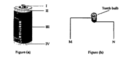
To make the bulb glow, free ends M and N of the circuit should be respectively connected to
View SolutionVarious parts on the outer surface of an electric cell are labelled as I, II, III, and IV respectively in figure (a). In figure (b), an incomplete circuit is shown. M and N are the free ends of this circuit.
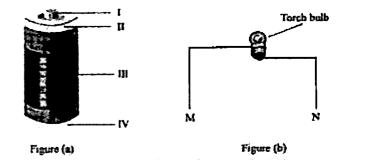
To make the bulb glow, free ends M and N of the circuit should be respectively connected to
View SolutionThe schematic diagram of an open circuit is shown in the given figure.
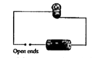
Opa ends Which of the following objects is inserted tightly in the gap to make the bulb glow?
View SolutionIn a potentiometer circuit, two wires of same matirial resistivity ρ, one of coross-section 'a' and other of radius of cross-section '2a' are joined in series. They are of length l and 2 l respectively. This combination acts as the potentiomter wire of length 3l. The emf of the primary circuit is ε and internal resistance is ρl2πa2 This cell is conneted to the potentiometer wire by a conducting wire of negligible resistance wire positive terninal of the cell conneted to one end (call it A) of longer wire. The negative terminal of the cell is conneted to one end of the samller wire. The remaining ends of the two wires are joined together. Find :
(i) The maximum voltage which can be balanced on the potentiometer wire.
(ii) The length, measured from point A, where cell of emd ε2 will balance.
(iii) if positive terminal of cell of emf ε2 and internal resistance pl2πa2 is connetcted to point A and other terminal is joined to the junction of the two wires, then find the current through this cell.
terminal is joined to the junction of the two wires, then find the current through this cell.
View SolutionBoojho has a cell and a single piece of connecting wire. Without cutting the wire in two, will he be able to make the bulb glow? Explain with the help of a circuit diagram.
View Solution

