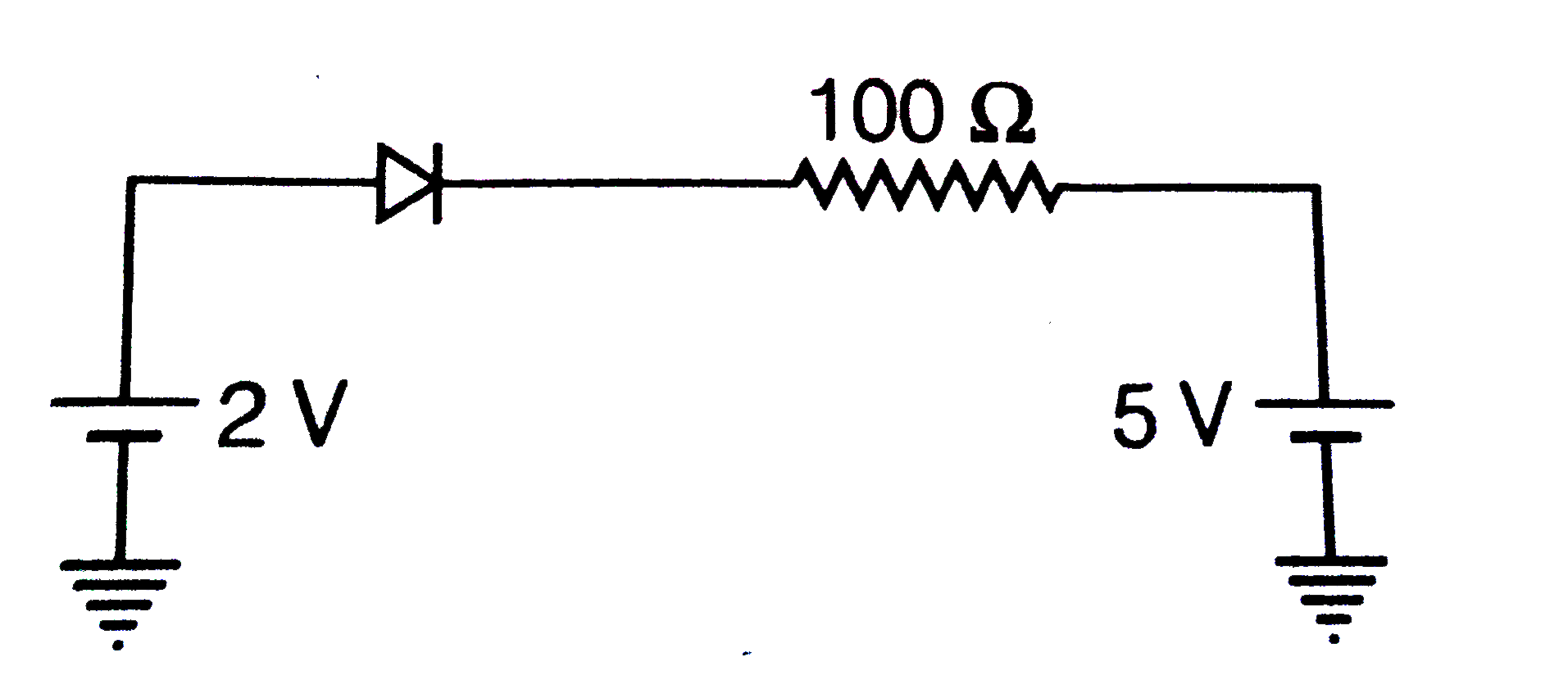
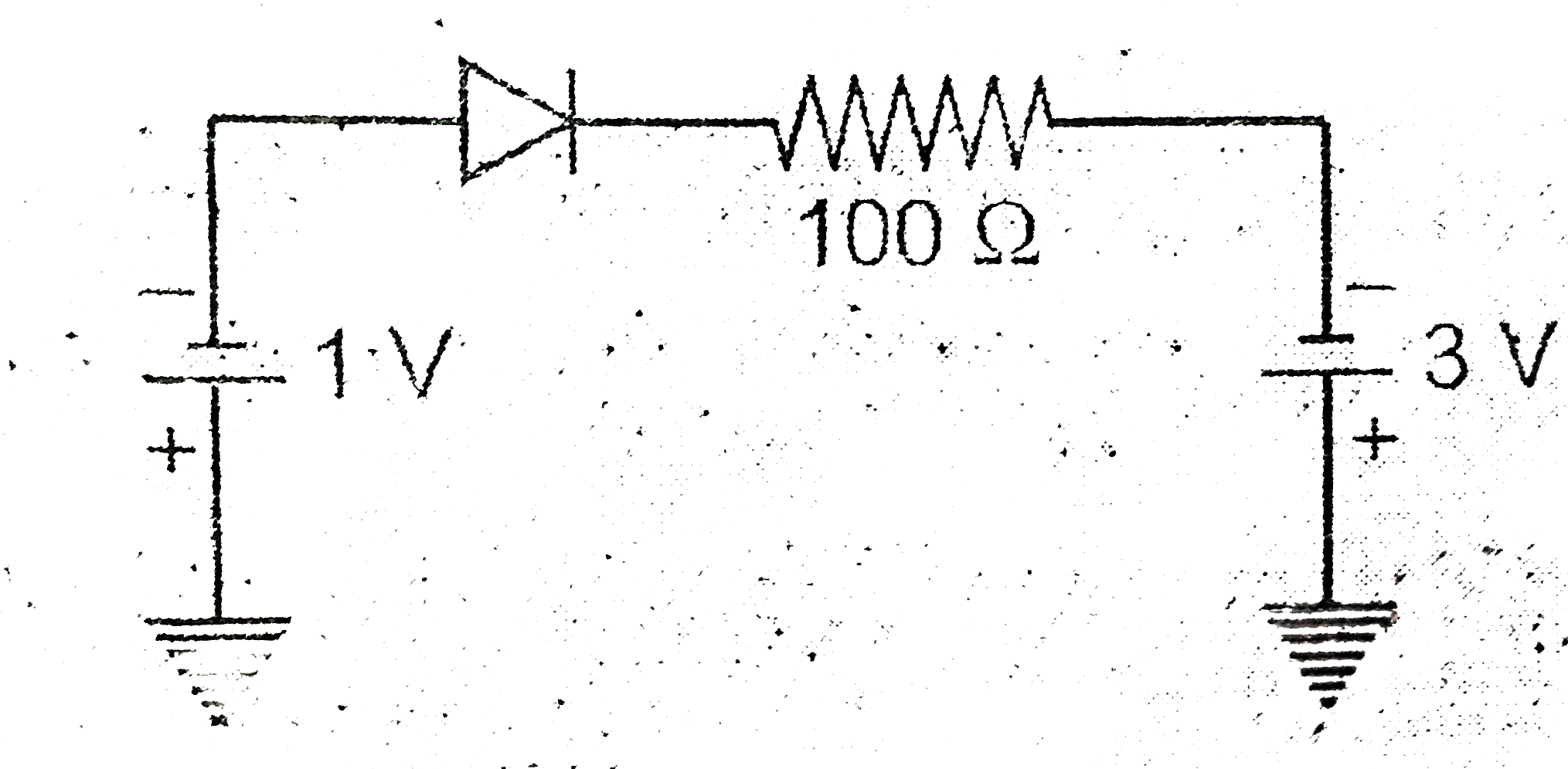
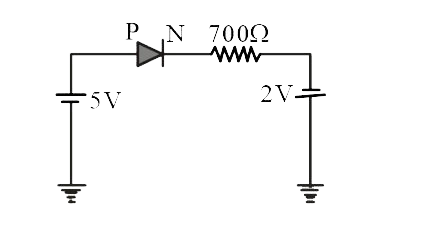
The current through an ideal PN junction shown in the following circuit diagram will be -
A
zero
B
1mA
C
10mA
D
30mA
Video Solution
Text Solution
The correct Answer is:A
The diode is in reverse biasing so current through zero.
|
Topper's Solved these Questions
- SEMICONDUCTOR ELECTRONICS BOOK - PHYSICS WALLAHCHAPTER - SEMICONDUCTOR ELECTRONICS EXERCISE - NEET PAST 5 YEAR QUESTION
23 Videos
- SEMICONDUCTOR ELECTRONICS BOOK - PHYSICS WALLAHCHAPTER - SEMICONDUCTOR ELECTRONICS EXERCISE - NEET PAST 5 YEAR QUESTION
23 Videos
- RAY OPTICS AND OPTICAL INSTRUMENTS BOOK - PHYSICS WALLAHCHAPTER - RAY OPTICS AND OPTICAL INSTRUMENTS EXERCISE - NEET PAST 5 YEARS QUESTIONS
16 Videos
- SYSTEM OF PARTICLES AND ROTATIONAL MOTION BOOK - PHYSICS WALLAHCHAPTER - SYSTEM OF PARTICLES AND ROTATIONAL MOTION EXERCISE - NEET PAST 5 YEARS QUESTIONS
22 Videos
Similar Questions
Knowledge Check
The current through and ideal p-n junction shown in the following circuit diagram will be
 AzeroB1 mAC10 mAD30 mA
In a PN-junction
AHigh potential at N side and low potential at P sideBHigh potential P side and low potential at N sideCP and N both are at smae potentialDUndeterminedThe current through the ideal diode as shown in the is
 A0AB0.02AC0.04AD0.06A
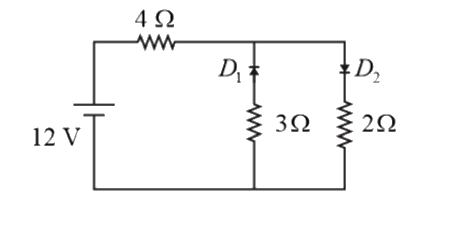
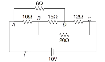
The current through the battery shown in the circuit is
View SolutionIn a PN-junction
View SolutionThe current through the ideal diode as shown in the figure is

View SolutionCurrent through the ideal diode as shown in figure is

View SolutionThe value of current I as shown in the given circuit diagram is
View Solution

