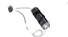
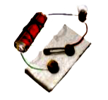
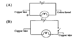
Observing that the bulb does not glow in the circuit shown in Fig. 14.11 A, Boojho changed the circuit as shown in Fig 14.11 B. He observed deflection in the magnetic compass.
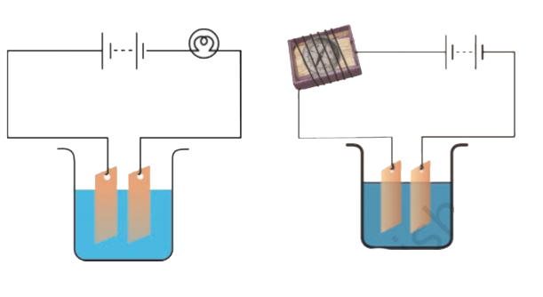
(i) What does the deflection in magnetic compass indicate?
(ii) Why did the bulb not glow in Fig.14.11 A?
(iii) What would be the effect of increase in the number of turns in the coil wound around the magnetic compass in Fig. 14.11B?
(iv) What will be observed if the number of cells are increased in the circuit shown in Fig. 14.11B?
Video Solution
Text Solution
(i) It indicates the presence of current in the circuit. (ii) The bulb did not glow because the current was not sufficient to make it glow. (iii) Deflection in the magnetic compass will increase. (iv) Deflection in the compass will increase further.
|
Topper's Solved these Questions
Similar Questions
Knowledge Check
In the circuit shown in Fig. 7.45,
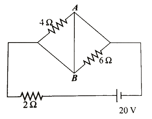 APower supplied by the battery is 200WBcurrent flowing in the circuit is 5ACPotential difference across the 4Ω resistance is equal to the potential difference across the 6Ω resistanceDcurrent in wire AB is zero
What is the current I in the circuit shown in adjoining Fig. ?
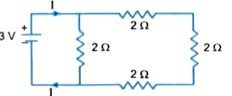 A2AB1.2AC1AD0.5A
In the circuit shown in fig, the resonant frequency is
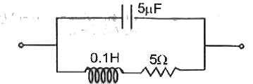 A75kcsB750kcsC7.5kcsD75mcs
Explain why the bulb would not glow in the arrangement shown in Fig. 12.13.
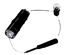
View SolutionWould the bulb glow in the circuit shown in figure ?

View SolutionExplain why the bulb would not glow in the arrangement shown in figure .

View SolutionWhat will be the reading in the voltmeter and ammeter of the circuit shown in fig.
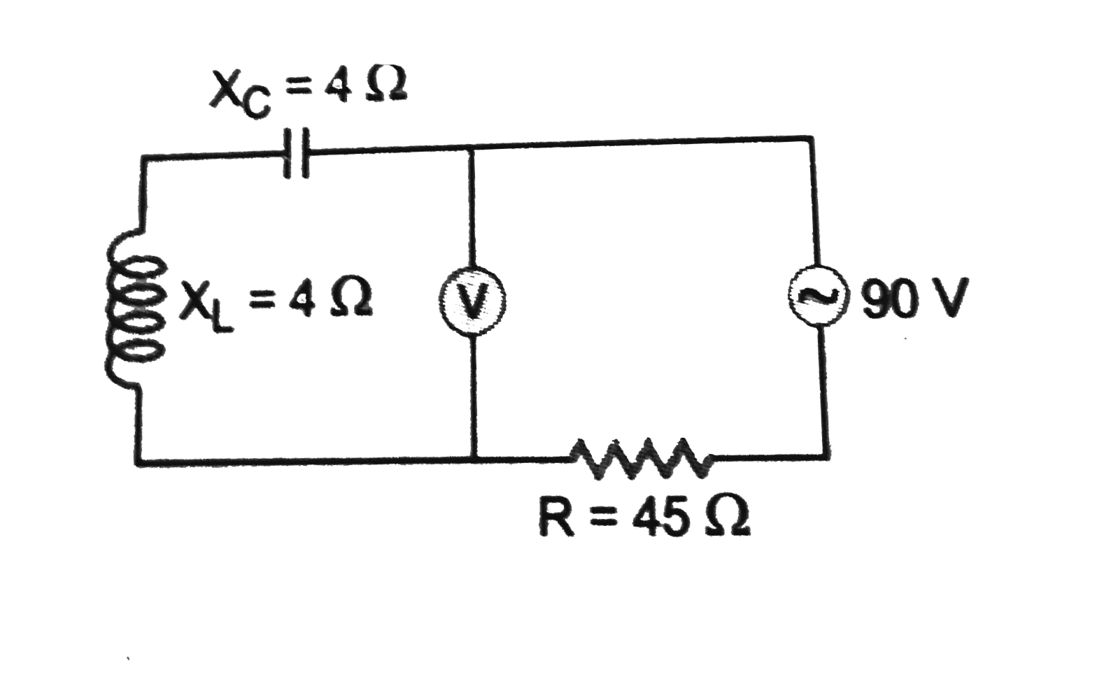
View SolutionIn which case, bulb glows in the circuit.
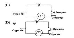
View Solution

