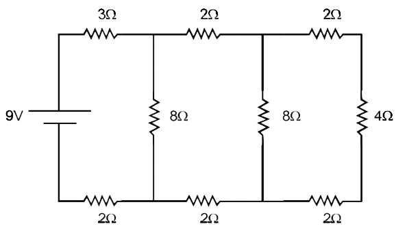
In the circuit shown in the figure, the current through the
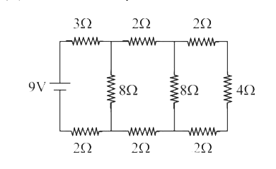
3Ωresistor is 0.50A
3Ωresistor is 0.25A
4Ωresistor is 0.50A
4Ωresistor is 0.25A
The net resistance of the circuit is as shown in the below figure.
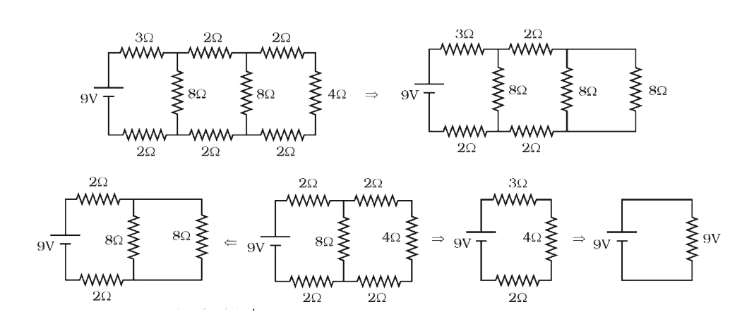
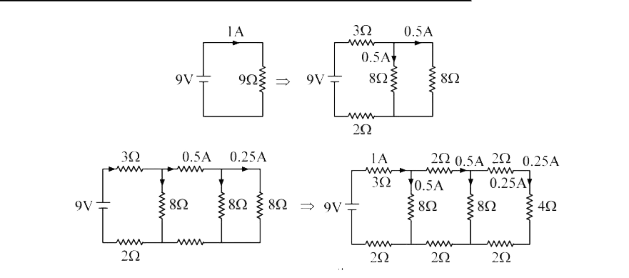
The current flowing in the circuit is I=V/R=9V/9Ω=1.0A . The flow of current in the circuit is as follows. Please note that the current gets divided into two equal parts if it passes through two equal resistances.
Topper's Solved these Questions
- BOOK - VMC MODULES ENGLISHCHAPTER - DC CIRCUITEXERCISE - LEVEL-1 JEE MAIN ARCHIVE93videos
DC CIRCUIT
- BOOK - VMC MODULES ENGLISHCHAPTER - CURRENT ELECTRICITYEXERCISE - IN-CHAPTER EXERCISE-F10videos
CURRENT ELECTRICITY
- BOOK - VMC MODULES ENGLISHCHAPTER - DYNAMICS OF A PARTICLEEXERCISE - JEE Advance (Archive) Level - II (SINGLE OPTION CORRECT TYPE )31videos
DYNAMICS OF A PARTICLE
Similar Questions
For the circuit shown in the figure,the rms current through the source is(Where E is in volt and t is in s)
_PHY_E06_110_Q01.png) View Solution
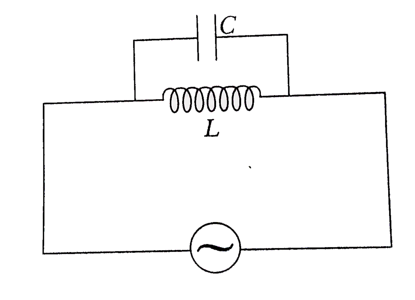
View SolutionFor the circuit as shown in the figure the current through the inductor is 1.6 A, while the current through the condenser is 0.4 A . Then, the current drawn from the source is
 View Solution
Knowledge Check
- Question 1 - Select One
From the Zener diode circuit shown in figure, the current through the Zener diode is
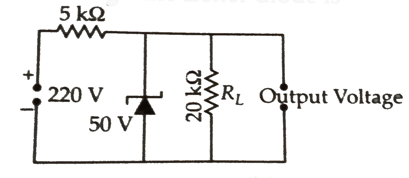 A34 mAB31.5 mAC36.5 mAD2.5 mA
 - Question 2 - Select One
In the circuit shown in figure the current flowing through 25 V cell is
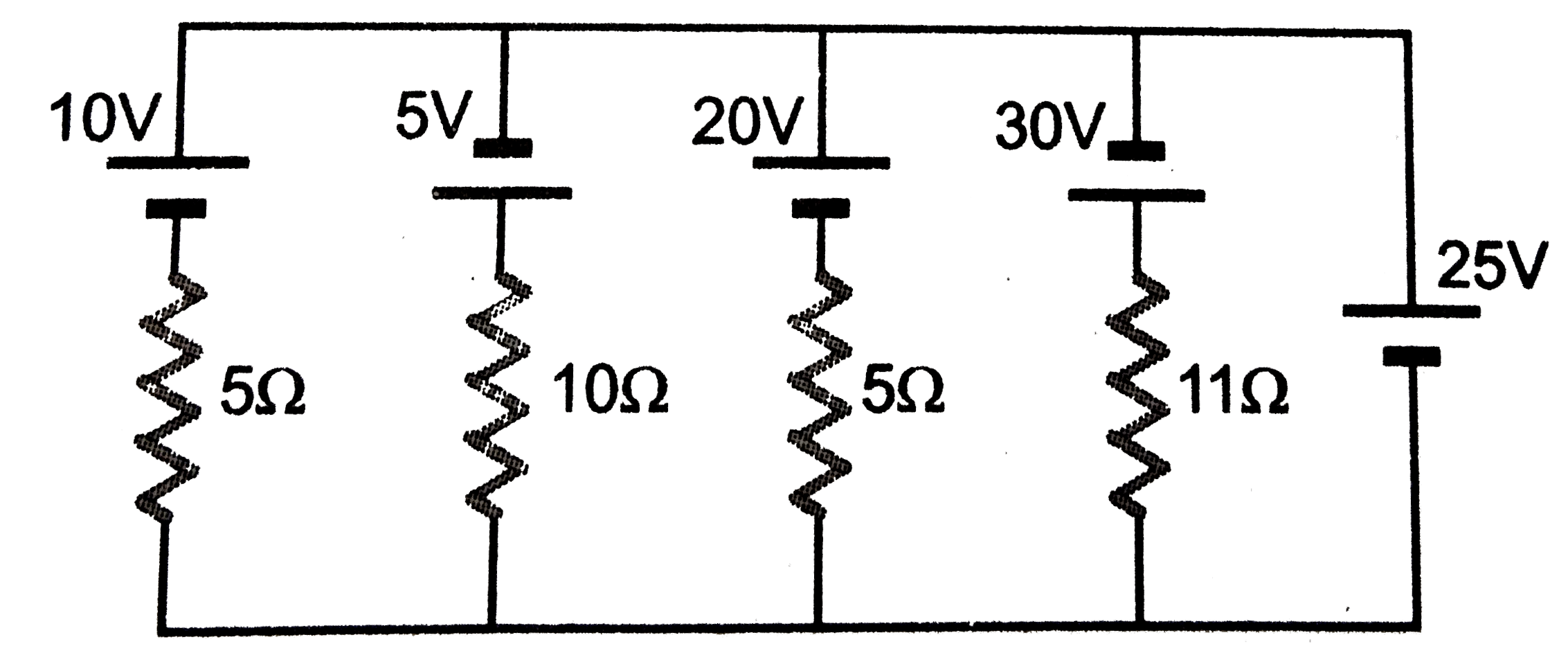 A7.2AB10AC12AD14.2A
 - Question 3 - Select One
In the circuit shown in figure the current flowing through 25 V cell is
 A7.2AB10AC12AD14.2A
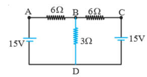
In the circuit shown in figure, find the current through the branch BD.
 View Solution
In the circuit shown in figure the current through
 View Solution
In the circuit shown in the figure , no current flows through the 8Omega resistor, then the potential difference between points A and B(V_A - V_B) is
_PHY_E01_001_Q01.png) View Solution
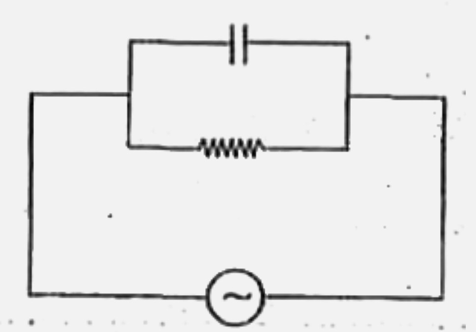
View SolutionIn the attemating current circuit shown in the figure, the currents through resistor and capacitor are 3 A and 4 A respectively. The current drawn from generator is
 View Solution
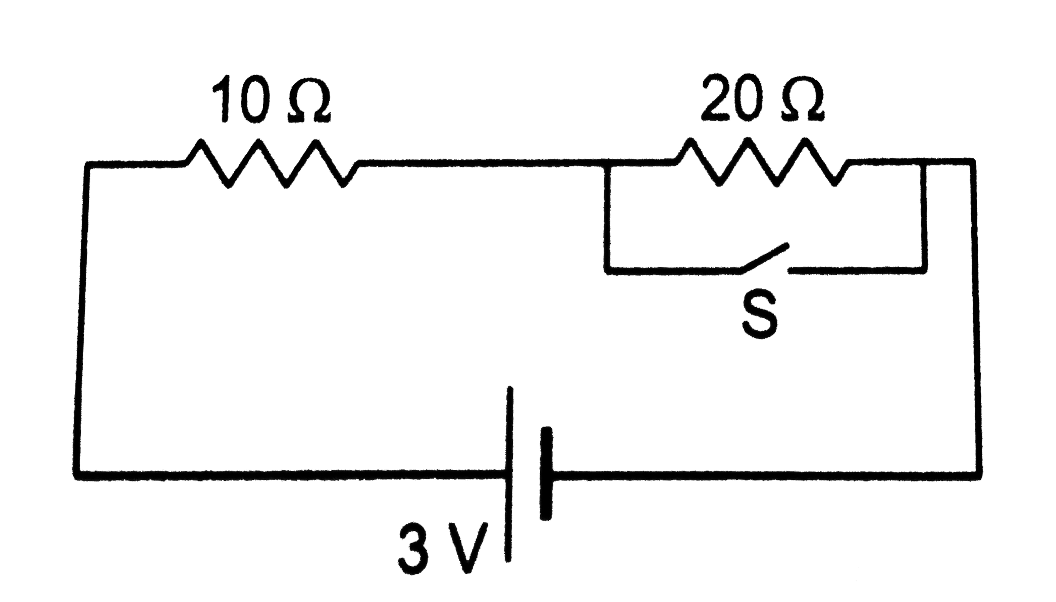
Consider the circuit shown in figure.Find the current through the10(Ω)resistor when the switch S is (a)open (b)closed .
 View Solution
