In the figure shown: (All batteries are ideal)
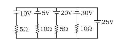
current through 25V cell is 20 A
current through 25V cell is 12.5 A
power supplied by 20V cell is 20 W
power supplied by 20 V cell is –20 W

Power supplied by 20V cell = (–1) (20) = – 20 W (as the cell is not supplying the power, it is eating the power, getting charged)
Topper's Solved these Questions
- DC CIRCUITBOOK - VMC MODULES ENGLISHCHAPTER - DC CIRCUITEXERCISE - LEVEL-2 DAILY TUTORIAL SHEET-3
10 Videos
- DC CIRCUITBOOK - VMC MODULES ENGLISHCHAPTER - DC CIRCUITEXERCISE - LEVEL-2 DAILY TUTORIAL SHEET-4
10 Videos
- DC CIRCUITBOOK - VMC MODULES ENGLISHCHAPTER - DC CIRCUITEXERCISE - LEVEL-2 DAILY TUTORIAL SHEET-1
10 Videos
- CURRENT ELECTRICITYBOOK - VMC MODULES ENGLISHCHAPTER - CURRENT ELECTRICITYEXERCISE - IN-CHAPTER EXERCISE-F
10 Videos
- DYNAMICS OF A PARTICLEBOOK - VMC MODULES ENGLISHCHAPTER - DYNAMICS OF A PARTICLEEXERCISE - JEE Advance (Archive) Level - II (SINGLE OPTION CORRECT TYPE )
31 Videos
Similar Questions
In the circuit shown,choose the correct option (All batteries are ideal)
_PHY_E05_285_Q01.png)
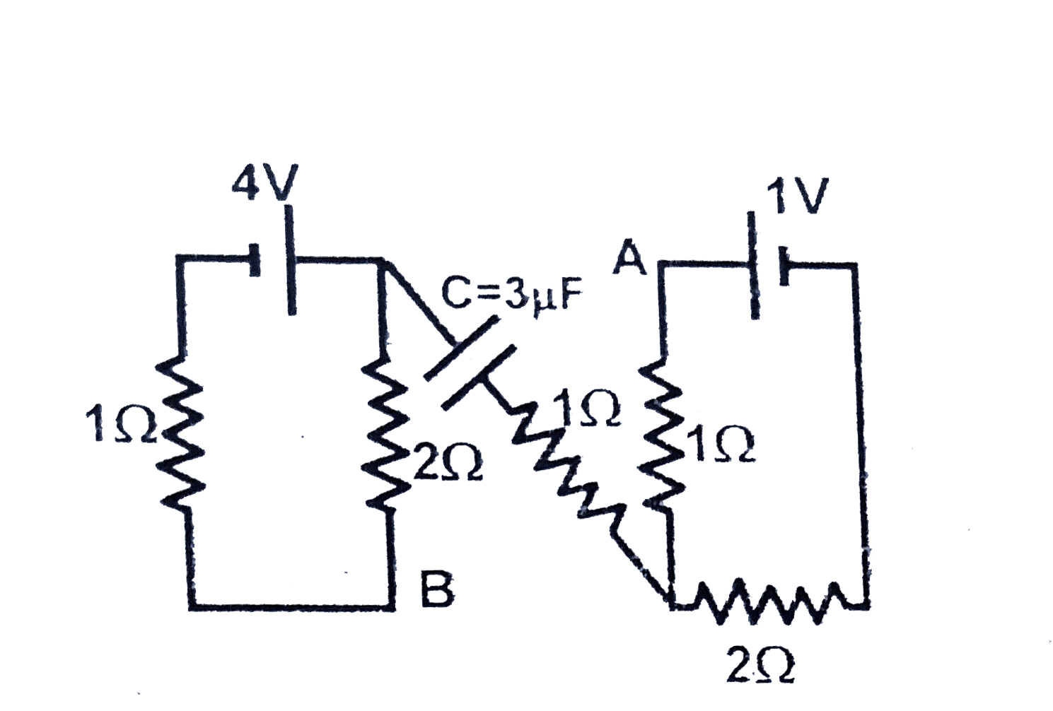
View SolutionIn the circuit shown in the adjacent figure, the batteries are ideal. The charge on the capacitor C is
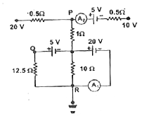
View SolutionIn the adjacent circuit shown , all ammeters and batteries are ideal , internal resistances of all the batteries are negligible . Point R is grouned Then, match the following.

View Solution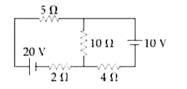
In the figure shown , the current in the 10 V battery is close to :
View SolutionAssertion : In the circuit shown in figure, battery is ideal. If a resistance R0 is cannected in parallel with R, then power across R will increase.
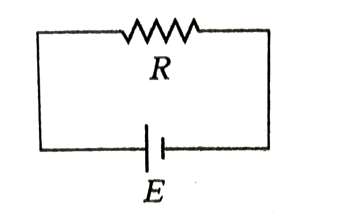
Reason : Current drawn from the battery will increase.
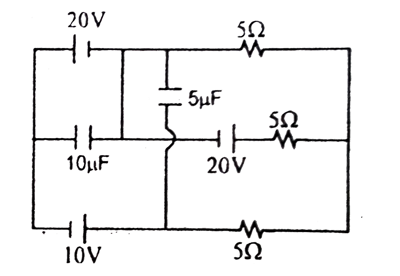
View SolutionFind the ratio of charges on 5μF and 10μF capacitor when circuit is in steady state. All the batteries are ideal.
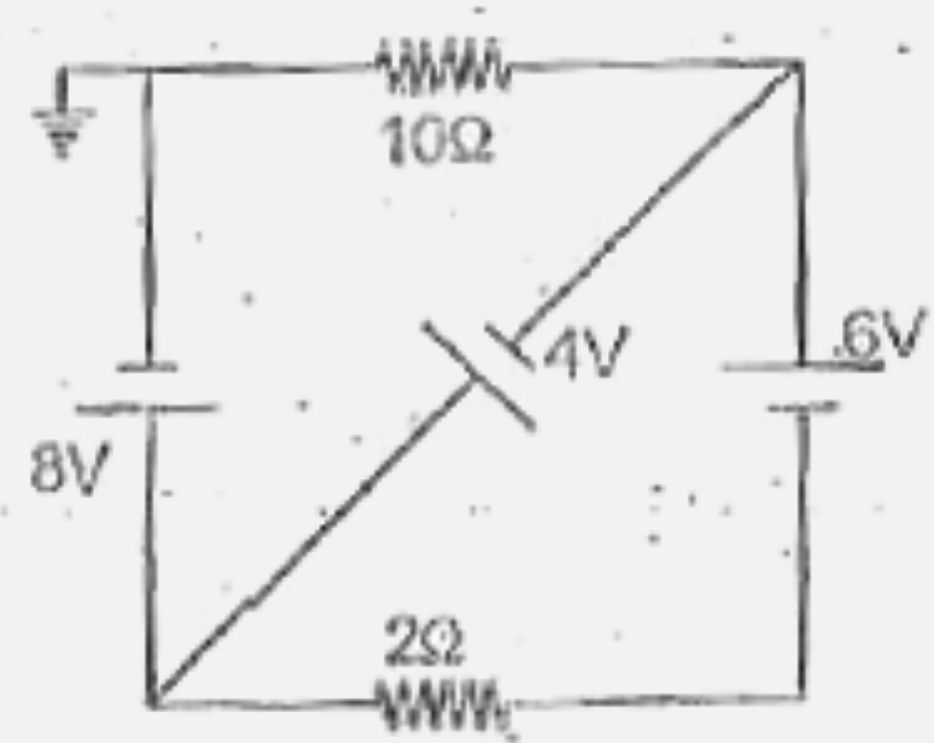
View SolutionIn the circuit shown in figure , all the cells are ideal . The currnet through 2Ω resistor is
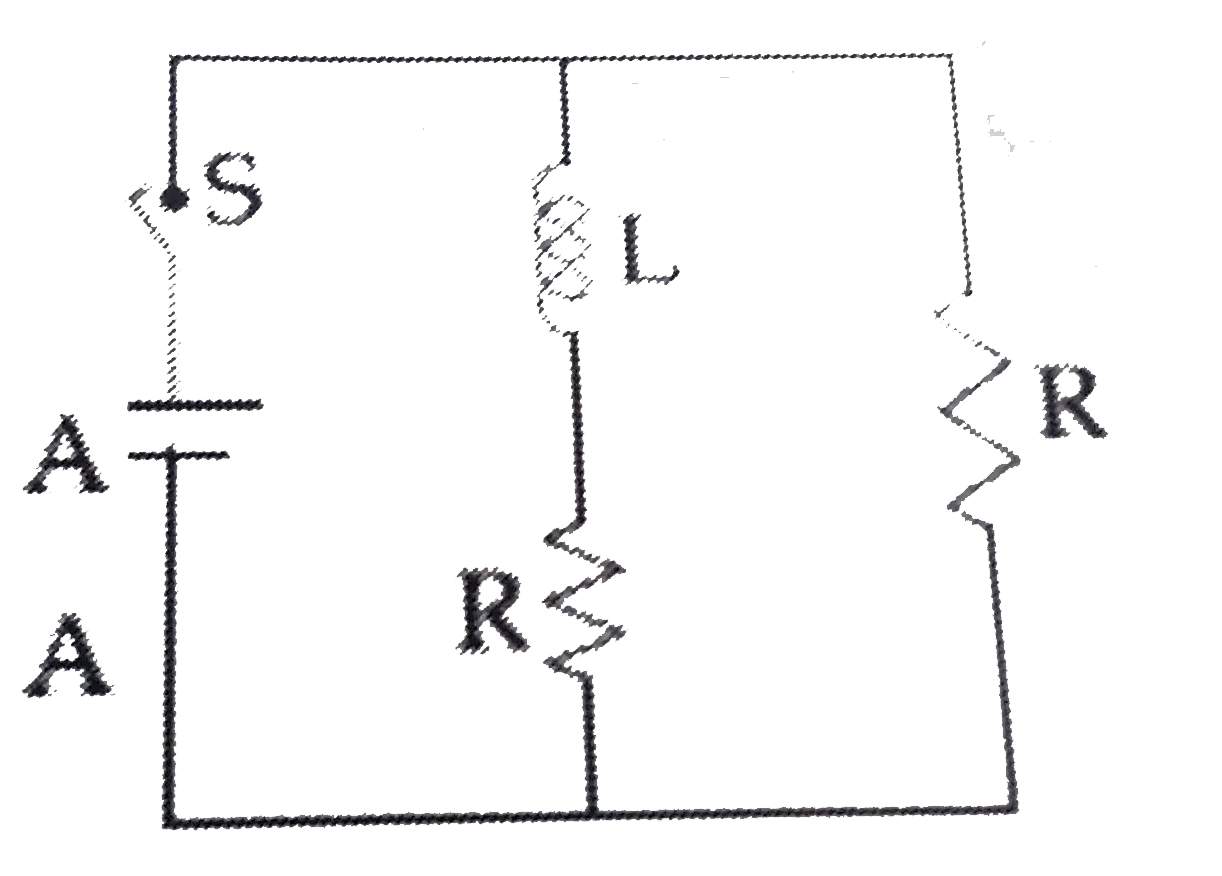
View Solutionin the figure shown , a circuit contains two identical resistors with resistance R=Ω and an inductance with L=2 H ,An ideal battery of 15 V is connected in the circuit what will be the current through the battery long after the switch is clossed ?
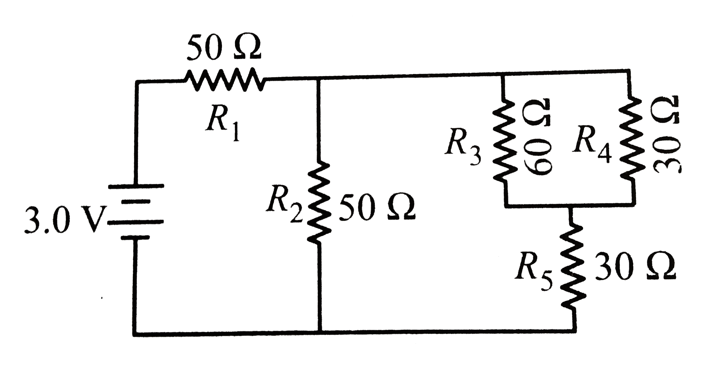
View SolutionIn the circuit shown, the resistances are given in ohms and the battery is assumed ideal with emf equal to 3.0 V.
View SolutionIn the process shown in the figure on an ideal diatomic gas, the value of q and ΔH respectively is
View Solution
