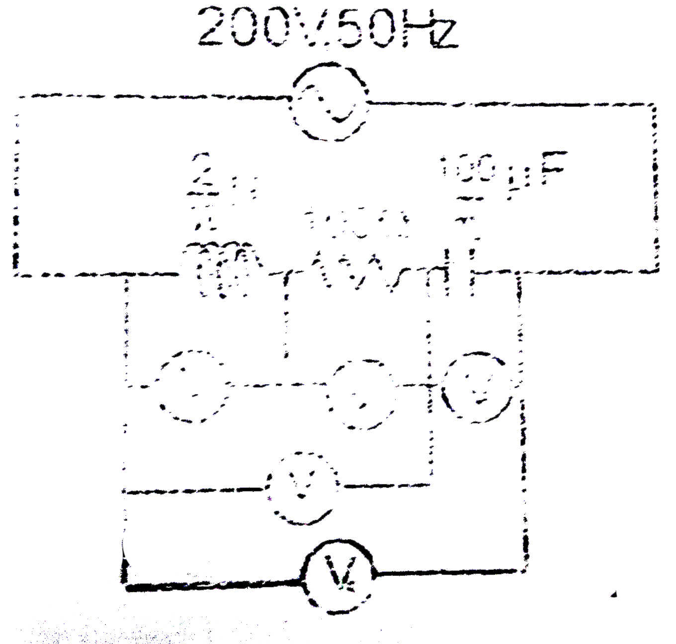
In the circuit shown in the figure, find:
(a) the reactance of the circuit
(b) impedance of the circuit
(c )the current
(d) readings of the ideal AC voltmeters(these are hot wire instruments and read rms values)
Video Solution
Text Solution
XL=2πfL=2π×50×2π=200Ω
XC=12π50100π×10−5=100Ω
The reactance of the circuit X=XL−XC=200−100=100Ω
Since X1>X2 the circuit is called inductive.
(b)impedance of the circuit Z=√R2+X2=√1002−1002=100√2Ω
( c)the current imax=VrmsZ=200100√2=√2A
(d)reading of the ideal voltmeter
V1:IrmsXL=200√2 Volt
V2:IrmsR=100√2 Volt
V3:IrmsXC=100√2 Volt
V4:Irms√R2+X2L=100√10 Volt
V5:IrmsZ=200 Volt, which also happens to be the voltage of source.
|
Similar Questions
Knowledge Check
In the circuit shown in figure, what will be the reading of the voltmeter ?
 A300 VB900 VC200 VD400 V
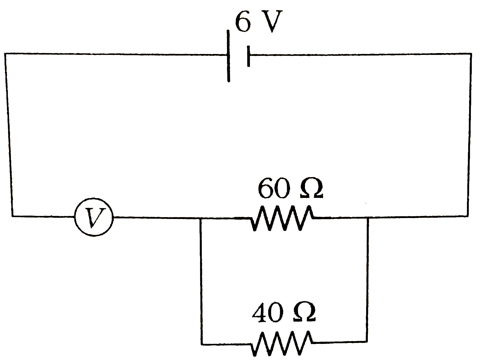
In the circuit shown in the figure, the voltmeter reading is
View SolutionIn the circuit shown in figure, reading of ammeter will
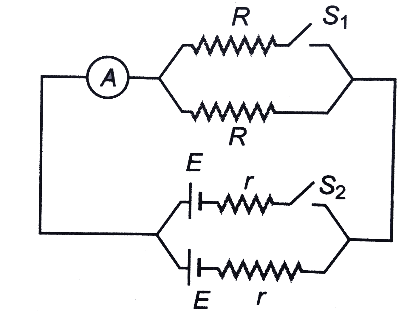
View SolutionIn the circuit shown in figure current in the circuit is
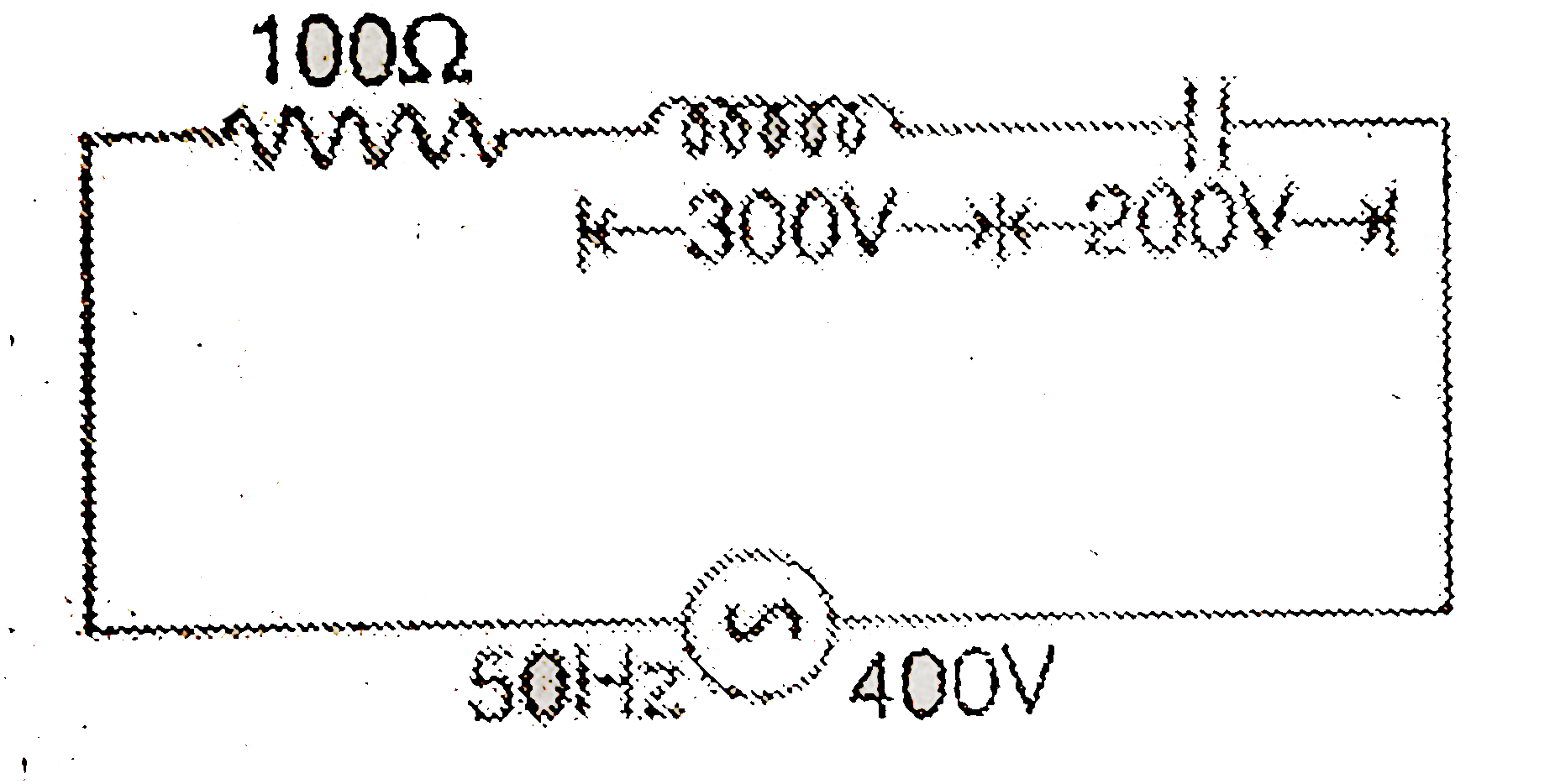
View SolutionIn the circuit shown in figureure, the reading of the AC ammeter is
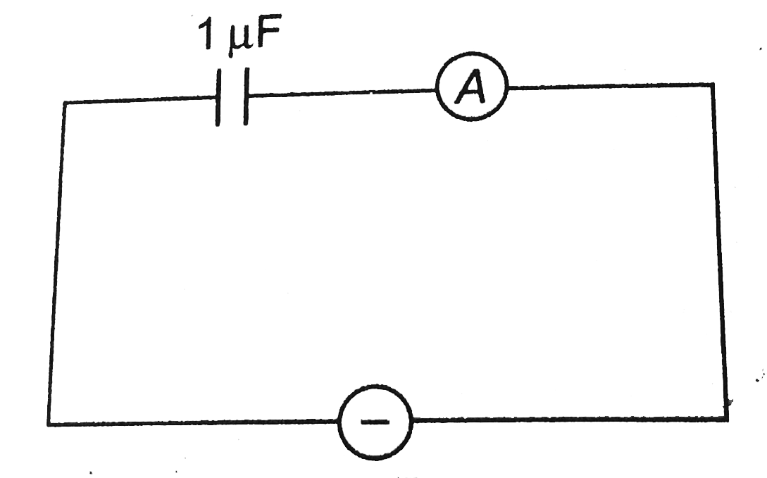 .
.
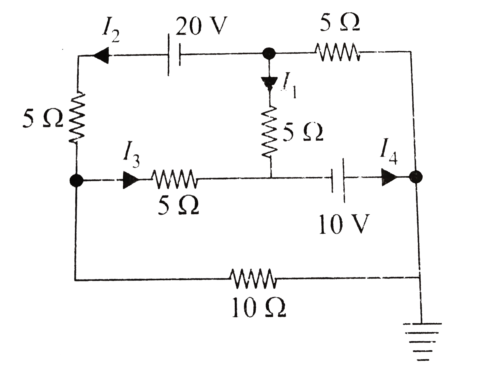
View SolutionIn the circuit shown in the figure
 .
.
The value of current I4 is
View SolutionIn the circuit shown in figure, the current / in circuit is
View SolutionReading of an ideal voltmeter in the circuit below is
View Solution
