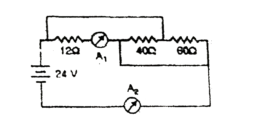
In the circuit of figure A1 and A2 are ideal ammeters. Then the reading in ammeter A2 is
0.4A
0.6A
2.0A
3.0A
The correct Answer is:D
1Req=1120+140+160=10+3+2120⇒Req=8Ω
i2=248=3Amp
Topper's Solved these Questions
Similar Questions
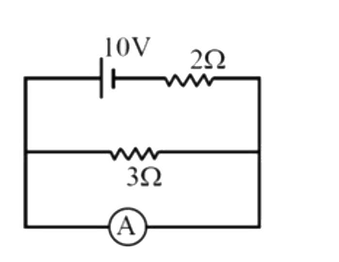
The reading of the ideal ammeter in the circuit is
View SolutionIn the circuit shown in figure, reading of ammeter will
View Solution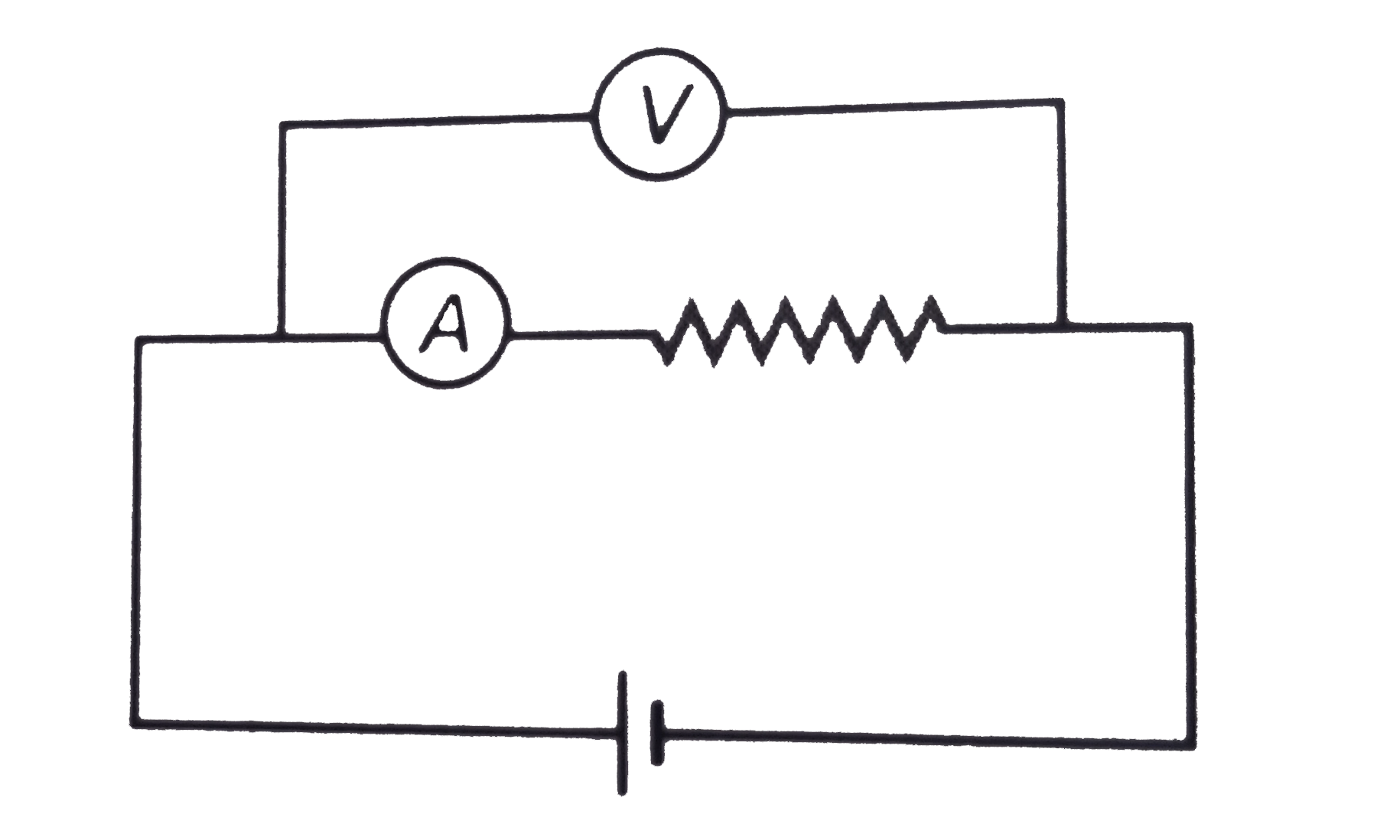
Assertion : In the circuit shown in figure ammeter and voltmeter are non-ideal when positions of ammeter and voltmeter are changed, reading of ammeter will increase while of voltmeter will decrease.
Reason : Resistance of an ideal ammeter is zero while that of an ideal voltmeter is infinite.
View SolutionIn the circuit shown in figure, what will be the readings of voltmeter and ammeter?
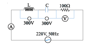
View SolutionAn ideal voltmeter V and ideal ammeter A are connected in a circuit as shown in the figure. If the reading of the voltmeter is 32 V, the reading of ammeter will be
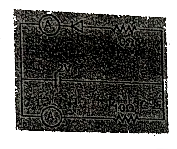
View SolutionIn the following circuit readings in ammeters A1 and A2 will be -
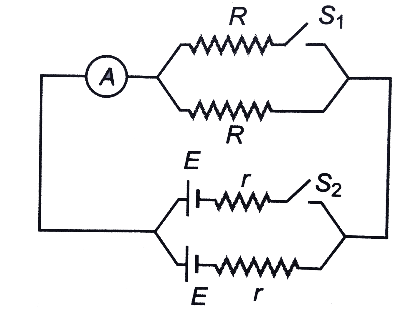
View SolutionIn the circuit shown in figure the reading of ammeter is the same with both switches open as with both closed. Then find the resistance R. (ammeter is ideal).
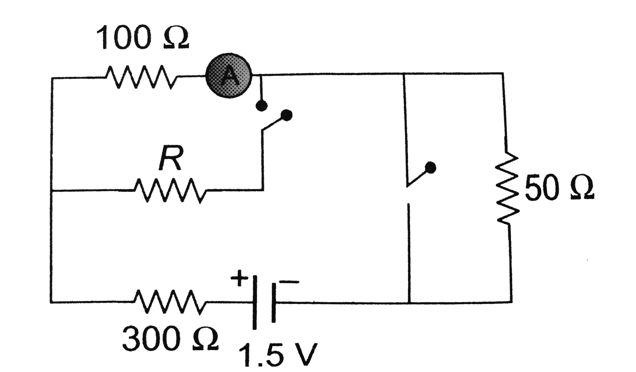
View SolutionIn the circuit shown in figure the reading of ammeter is the same with both switches open as with both closed. Then find the resistance R. (ammeter is ideal).

View SolutionThe reading of ammeter in the circuit shown in the figure is
_PHY_E05_104_Q01.png)
View SolutionThe reading of ammeter in the circuit shown in the figure is
_PHY_E05_032_Q01.png)
View Solution

