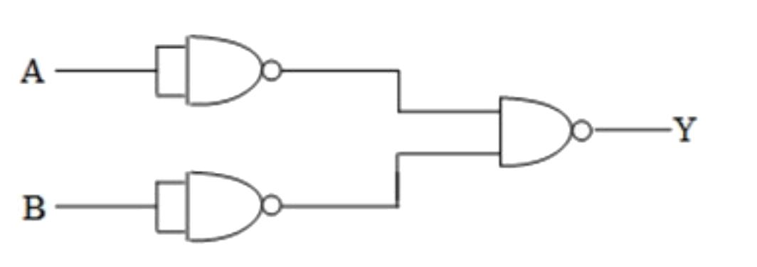
The circuit is equivalent to

A
AND gate
B
NAND gate
C
NOR gate
D
OR gate
Video Solution
Text Solution
The correct Answer is:C
The gate circuit can be shown by giving two inputs A and B.

Output of NOR gate Y1=¯¯¯¯¯¯¯¯¯¯¯A+B
Output NAND gate, Y2=¯¯¯¯¯¯¯¯¯Y1.Y2
=¯¯¯¯Y1+¯¯¯¯Y1
=¯¯¯¯¯¯¯¯¯¯¯¯¯¯¯¯¯¯¯¯¯¯A+B+¯¯¯¯¯¯¯¯¯¯¯¯¯¯¯¯¯¯¯¯¯¯A+B
=(A+B)+(A+B)
=A+B
Out of NOT gate Y=¯¯¯¯Y2
=¯¯¯¯¯¯¯¯¯¯¯A+B
Which is the output of NOR gate. Alternative:

NORNANDNOTA B Y1Y1Y1Y2Y0 0 111010 1 000101 0 000101 1 00010
Same as NOR gate
NOR Gate0 0 10 1 01 0 01 1 0.
|
Topper's Solved these Questions
- SEMICONDUCTORSBook:RESONANCE ENGLISHChapter:SEMICONDUCTORSExercise:Exercise 2
Explore 16 Videos
- REVISION DPPBook:RESONANCE ENGLISHChapter:REVISION DPPExercise:All Questions
Explore 463 Videos
- SIMPLE HARMONIC MOTION Book:RESONANCE ENGLISHChapter:SIMPLE HARMONIC MOTION Exercise:Advanced Level Problems
Explore 13 Videos
Similar Questions
Knowledge Check
The circuit as shown in the figure is equivalent to
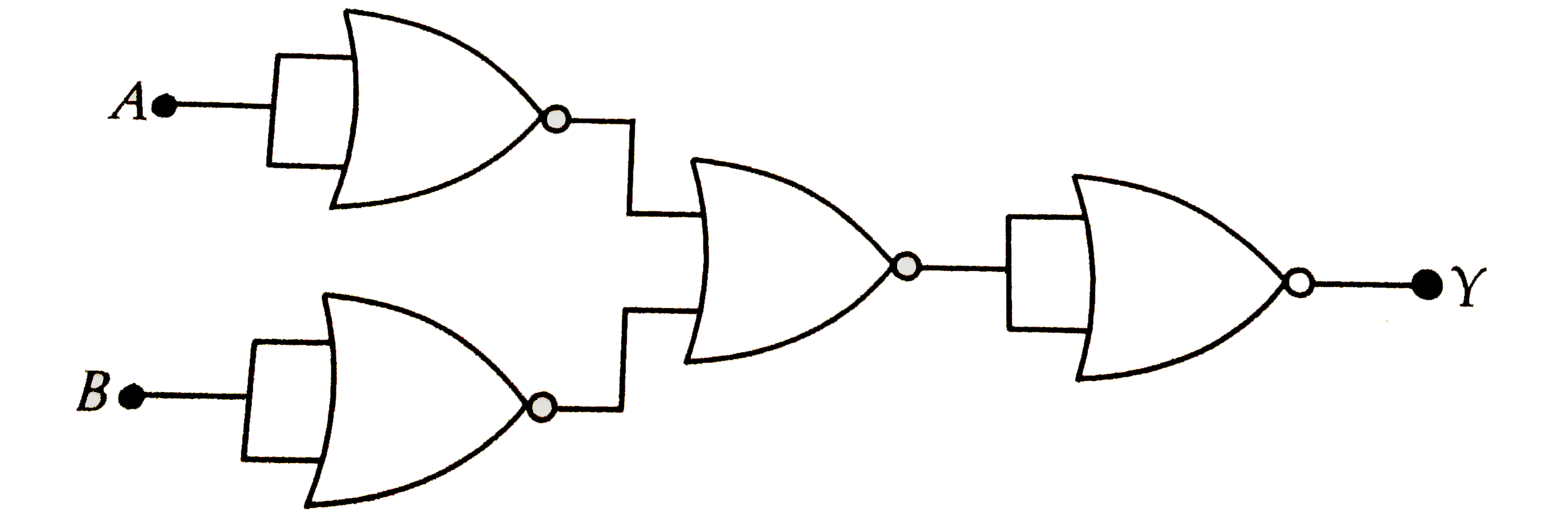 AAND gateBNOT gateCOR gateDNAND gate
The circuit given in figure, is equivalent to
 AAND gateBOR gateCNOT gateDNAND gate
Five equal resistance each of value R are connected in a circuit . Find equivalent resistance of the network between points A and C
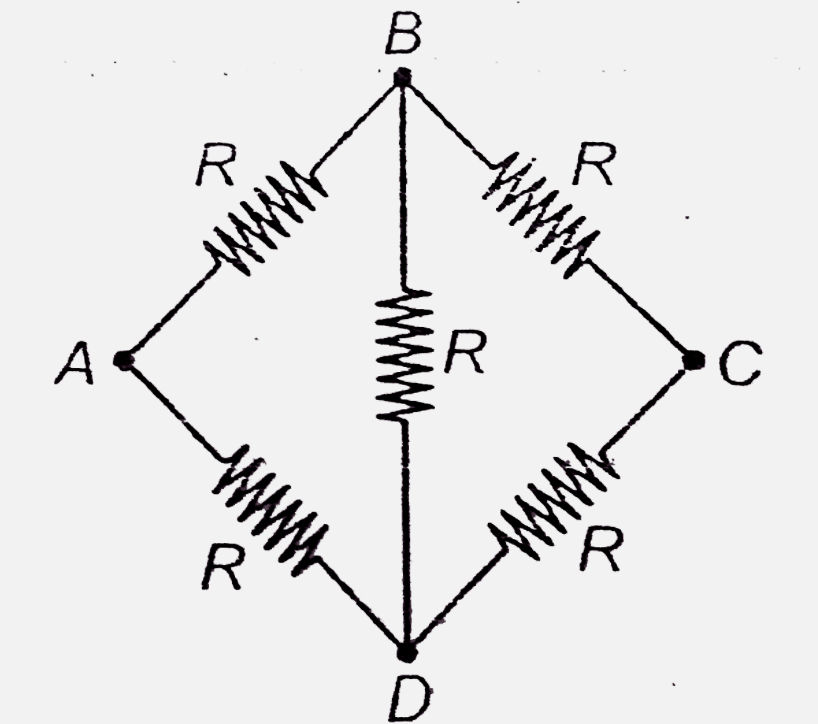
View SolutionPassage :

From the above circuit, equivalent internal resistance of the combination is
View SolutionThe logic gate equivalent to the given logic circuit is :
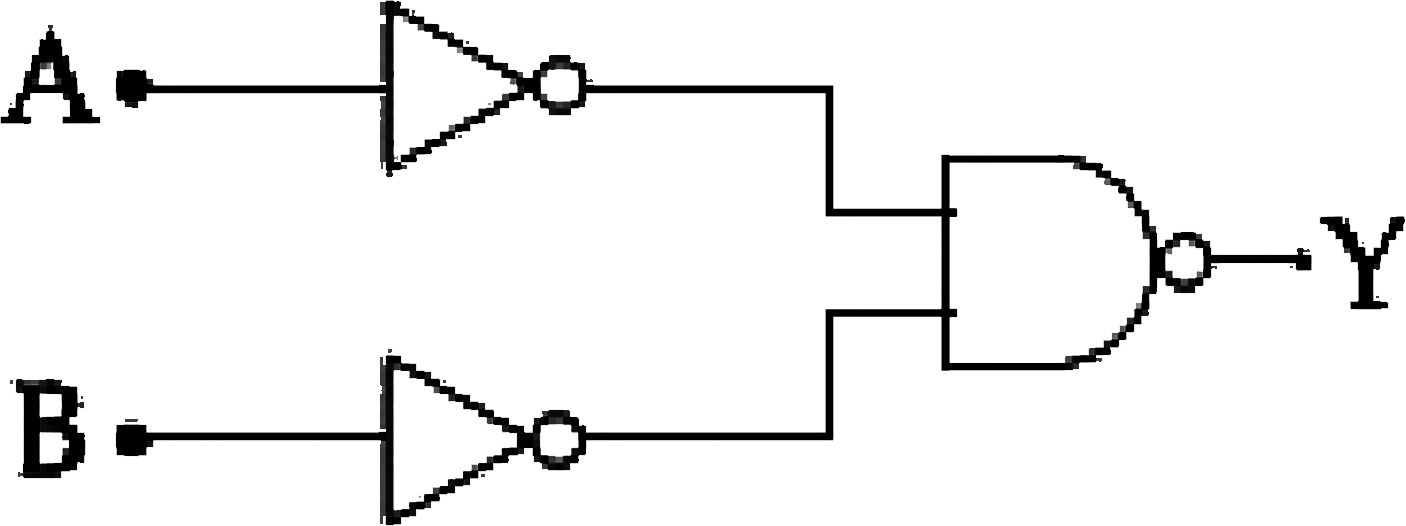
View SolutionFor the following circuit the equivalent capacitance P and Q is

View SolutionGiven the circuit :
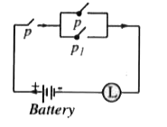
Which of the following is equivalent to the above circuit ?
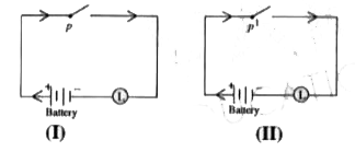
The true statement in the above is/are
View SolutionConsider the shown circuit. The capacitor is uncharged when the swith is closed at time t=0. Which of the circuit given in option is equivalent to the shown circuit as t approaches infinity?
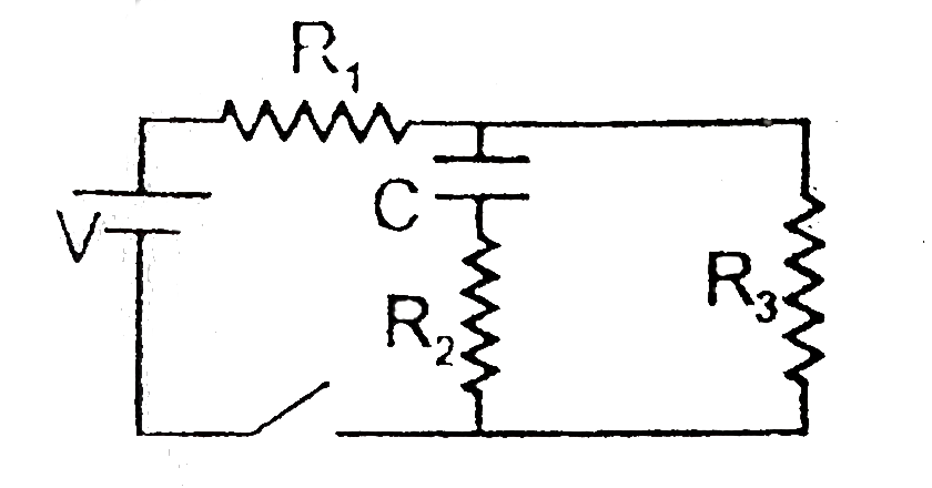
View Solution


