Figure 3.15(a) shown two circular rings of radii a and b (a>b) joined together with wires of negligible resistance. Figure 3.15(b) shown thew pattern obtained by folding the small loop in the plane of the large loop.
(a) 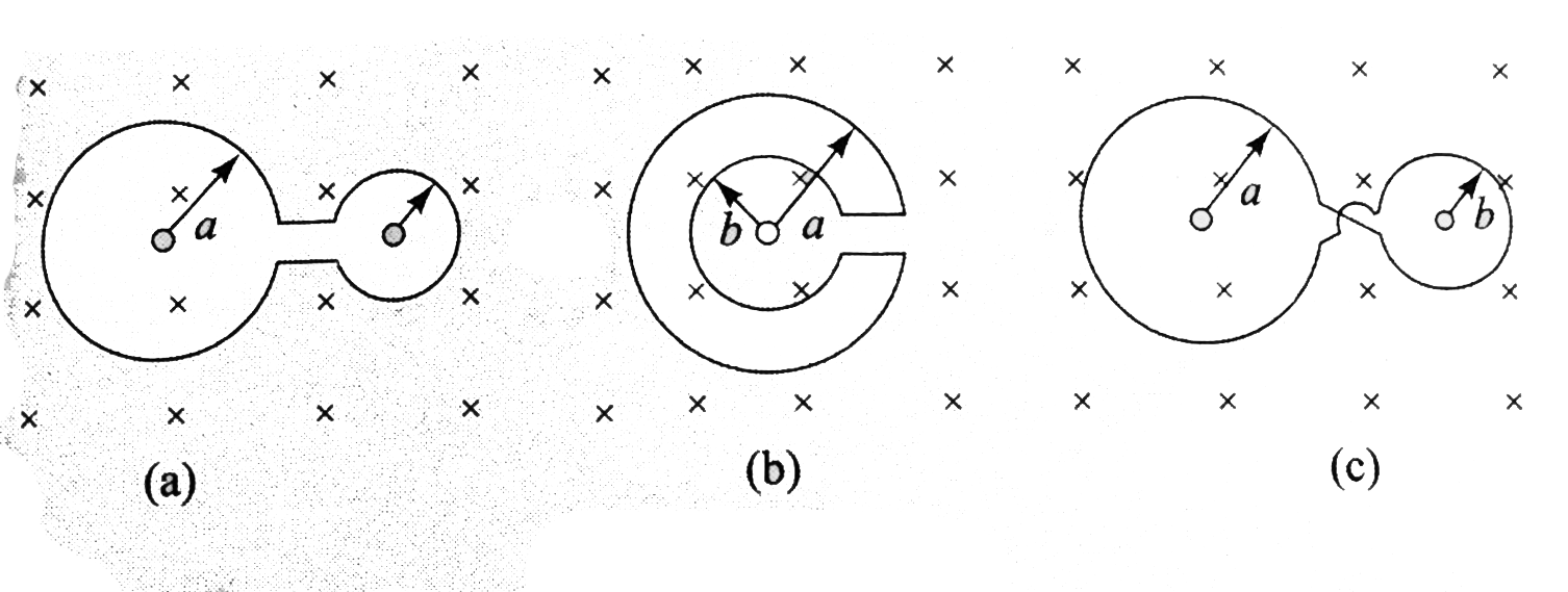
The pattern shown in Fig.3.15( c ) is obtained by twisting the small loop of Fig.3.15(a) through 180∘.
All the three arrangement are placed in a uniform time varying magnetic field dB/dt=k, perpendicular to the plane of the loops. if the resistance per unit length of the wire is λ, then determine the induced current in each case.
(a) ϕB=π(a2+b2)B
ε=dϕdt=π(a2+b2)×dBdt=π(a2+b2)k
Induced current, I=εR=π(a2+b2)kλ[2λ(a+b)]=k(a2+b2)2λ(a+b)
(b) ϕB=πa2B−πb2B=πB(a2−b2)
ε=dϕBdt=πdBdt×(a2−b2)=πk(a2−b2)
Induced current, I=εR=πk(a2−b2)2πλ(a+b)=k(a−b)2λ
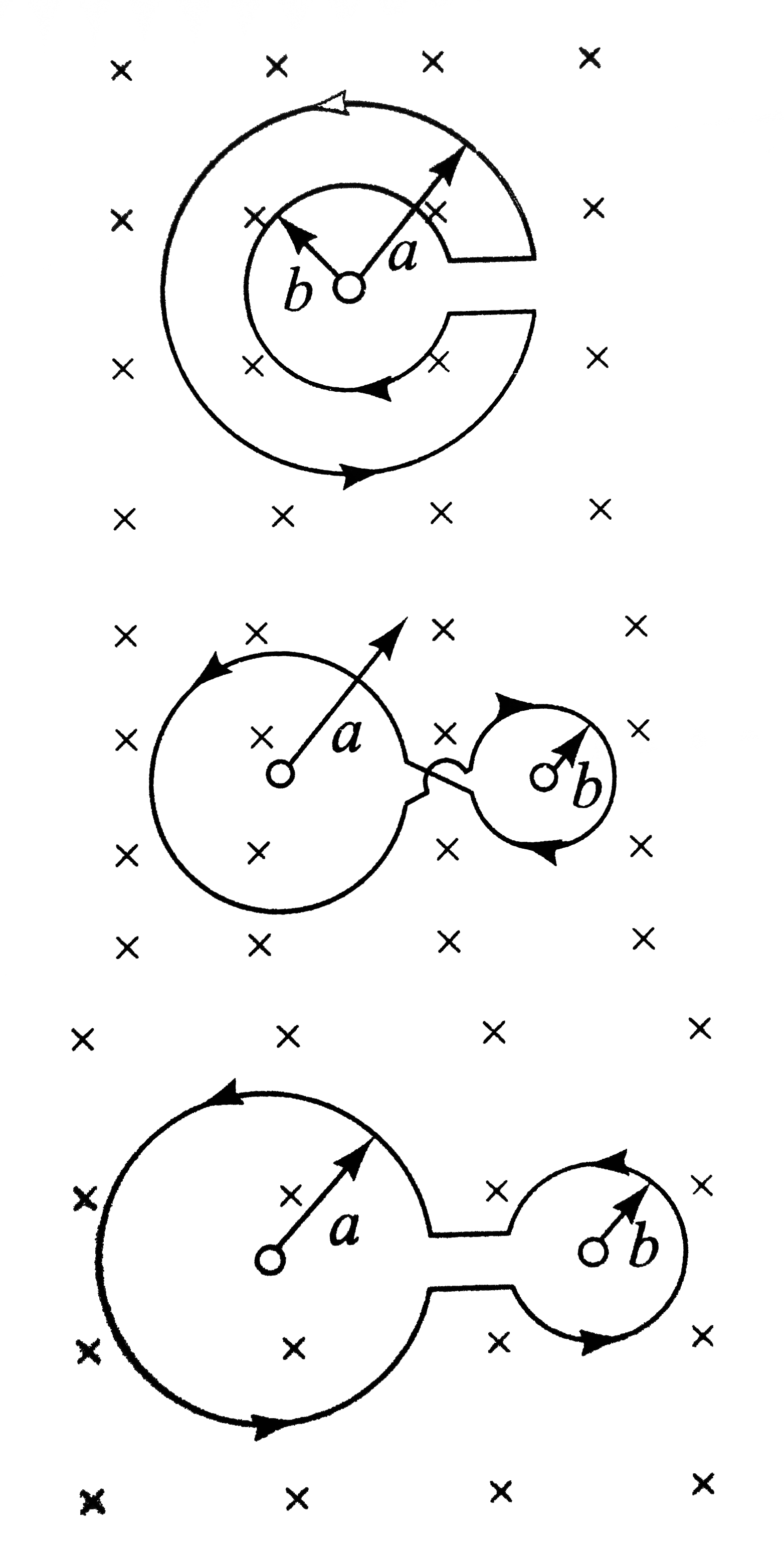


( c) Here induced emf in both loops will oppose each other, hence effective flux is given by
ΦB=πa2B−πb2B=πB(a2−b2)
→ ε=dΦBdt=πk(a2−b2)
induced current, I=εR=k(a−b)2λ
Topper's Solved these Questions
- ELECTROMAGNETIC INDUCTIONBOOK - CENGAGE PHYSICS ENGLISHCHAPTER - ELECTROMAGNETIC INDUCTIONEXERCISE - Solved Example
5 Videos
- ELECTROMAGNETIC INDUCTIONBOOK - CENGAGE PHYSICS ENGLISHCHAPTER - ELECTROMAGNETIC INDUCTIONEXERCISE - Exercise 3.1
15 Videos
- ELECTRICAL MEASURING INSTRUMENTSBOOK - CENGAGE PHYSICS ENGLISHCHAPTER - ELECTRICAL MEASURING INSTRUMENTSEXERCISE - M.C.Q
2 Videos
- ELECTRON,PHONTS,PHOTOELECTRIC EFFECT & X-RAYSBOOK - CENGAGE PHYSICS ENGLISHCHAPTER - ELECTRON,PHONTS,PHOTOELECTRIC EFFECT & X-RAYSEXERCISE - dpp 3.3
15 Videos
Similar Questions
Find the equivalent resistance between A and B.

View SolutionFigure shows two circular rings of radii a & b (a gt b) joined together by wire of negligible resistance. If the arrangement is placed in a time varying magnetic field, dBdt=k and if the resistance per unit length of wire is λ, then induced current is
View SolutionA circular loop of wire is carring a current i (as shown in the figure). On applying a uniform magnetic field inward perpendicular to the plane of the loop, the loop
View SolutionA loop shown in the figure is immersed in the varying magnetic field B=B0t, directed into the page. If the total resistance of the loop is R, then the direction and magnitude of induced current in the inner circle is
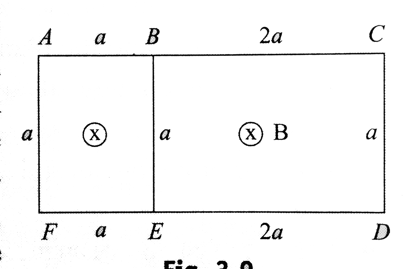
View SolutionA closed loop with the geometry shown in Fig. 3.9 is placed in a uniform magnetic field direction into the plane of the paper. If the magnetic field decreases with time, determine the direction of the induced emf in this loop.
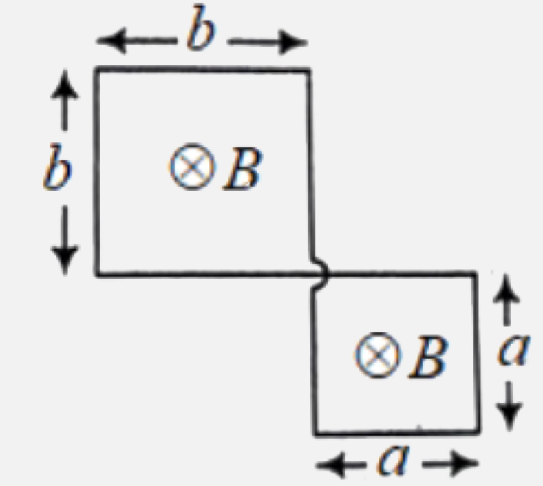
View SolutionA conducting loop (as shown) has total resistance R. A uniform magnetic field B=γt is applied perpendicular to plane of the loop where γ is a constant and t is time. The induced current flowing through loop is
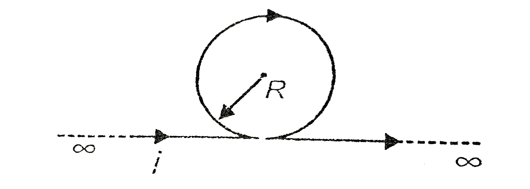
View SolutionFind the magnetic field at the centre of the circular loop shown in figure.
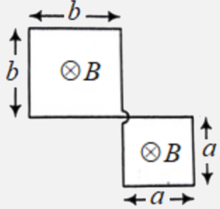
View SolutionA conducting loop (as shown) has total resistance R. A uniform magnetic field B=γt is applied perpendicular to plane of the loop where γ is constant and t is time. The induced current flowing through loop is
View SolutionA loop PQR carries a current i=2A as shown in the figure. A uniform magnetic field B = 2T exists in space parallel to the plane of the loop . The magnetic torque on the loop is
View SolutionIn a closed loop, which has some inductance but negligible resistance, uniform but time varying magentic field is applied directed into the plane of the loop. Variation of field with time is shown in Fig. Initially current in loop was zero. Then .
View Solution
