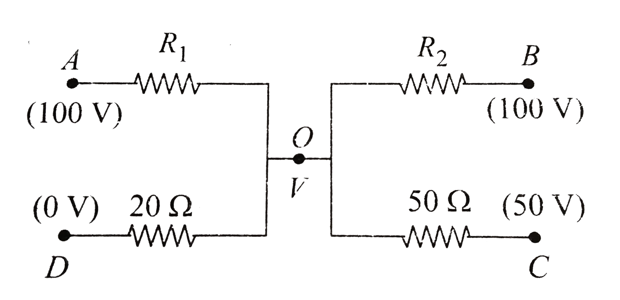
In the circuit as shown, it is given that R1/R2=1/2 and potential at O is V. The resistance R2 is-
80Ω
16Ω
240Ω
any value
The correct Answer is:D
d. Given, R2=2R1
For AO,100−V=i1R1
For BO,100−V=i2(2R2)
For OD,V−0=i3(20)
For OC,V−50=(i1+i22−i3)(50)
VR1=50R1=(3i12×50−i3×50)R1
From Eqs. (i) and (iii),
VR1=50R1=75(100−V)−2.5VR1
3.5VR1−50R1 = 7500 - 75V<br>IfVlt75V,thenRHSgt0.<br>So,LHS gt0<br>3.5 V gt 50(sinceR1≠0)
V>503.5
From Eq. (v), V=20V.
70R1−50R1=7500−1500=6000
R1=300Ω
R2=2R1=600Ω
From Eq. (v),
3.5VR1+75V=7500+50R1
For any value of R1 Vgt0.
Topper's Solved these Questions
- MISCELLANEOUS VOLUME 3BOOK - CENGAGE PHYSICS ENGLISHCHAPTER - MISCELLANEOUS VOLUME 3EXERCISE - Interger Answer type
20 Videos
- MISCELLANEOUS VOLUME 3BOOK - CENGAGE PHYSICS ENGLISHCHAPTER - MISCELLANEOUS VOLUME 3EXERCISE - Fill in the blanks
10 Videos
- MISCELLANEOUS VOLUME 3BOOK - CENGAGE PHYSICS ENGLISHCHAPTER - MISCELLANEOUS VOLUME 3EXERCISE - Assertion and Reason Type
8 Videos
- MAGNETIC FIELD AND MAGNETIC FORCESBOOK - CENGAGE PHYSICS ENGLISHCHAPTER - MAGNETIC FIELD AND MAGNETIC FORCESEXERCISE - Multiple Correct Answer type
2 Videos
- MISCELLANEOUS VOLUME 5BOOK - CENGAGE PHYSICS ENGLISHCHAPTER - MISCELLANEOUS VOLUME 5EXERCISE - Integer
12 Videos
Similar Questions
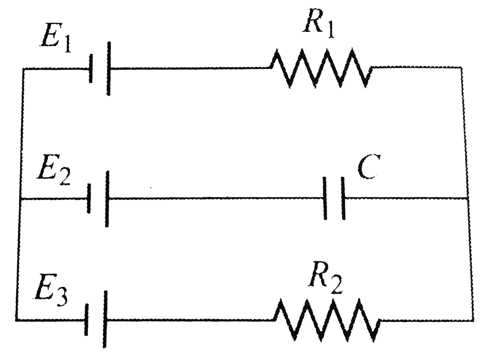
In the circuit shown , the batteries have emf E1=E2=1V,E3=2.5V, and the resistance R1=10Ω,R2=20Ω, Capacitance C=10μF. The charge on the left plate of the charge on the left plate of the capacitor C at steady state is
View SolutionConsider the circuit shown in fig.
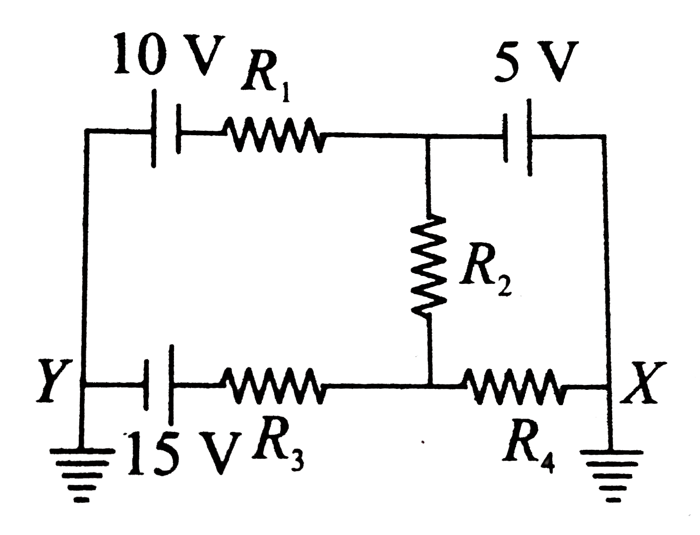
Assuming R1=2Ω, current passing through resistance R1 is
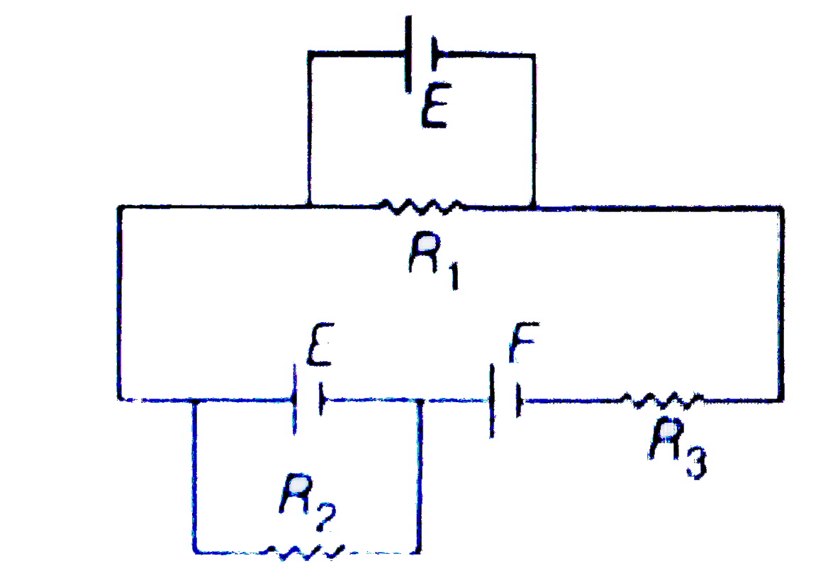
View SolutionIn the circuit shown in figure , R1=R2=R3=R. Match the following
View SolutionIn the circuit shown in figure, the emfs of batteries are E1, and E2 which have internal resistances R1, and R2. At what value of the resistance R will the thermal power generated in it be the highest? What it is?
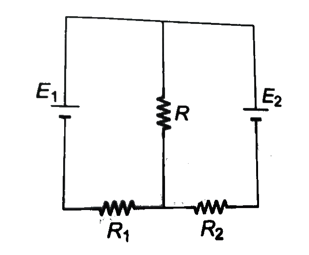
View SolutionIn the circuit shown in Fig. the emf of the sources is equal to ξ=5.0V and the resistances are equal to R1=4.0Ω and R2=6.0Ω. The internal resistance of the source equals R=1.10Ω. Find the currents flowing through the resistances R1 and R2.

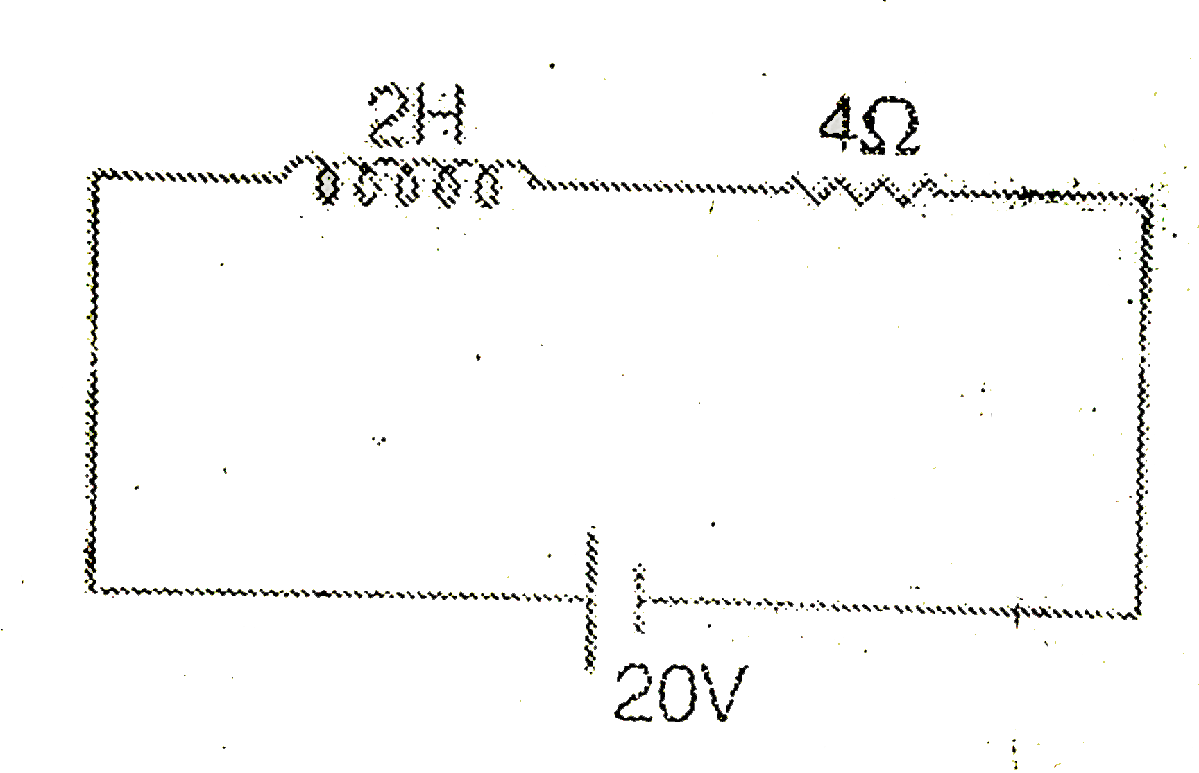
View SolutionIn the L-R circuit as shown in figure, potential difference across the resistance at some instant is 4 V. Then
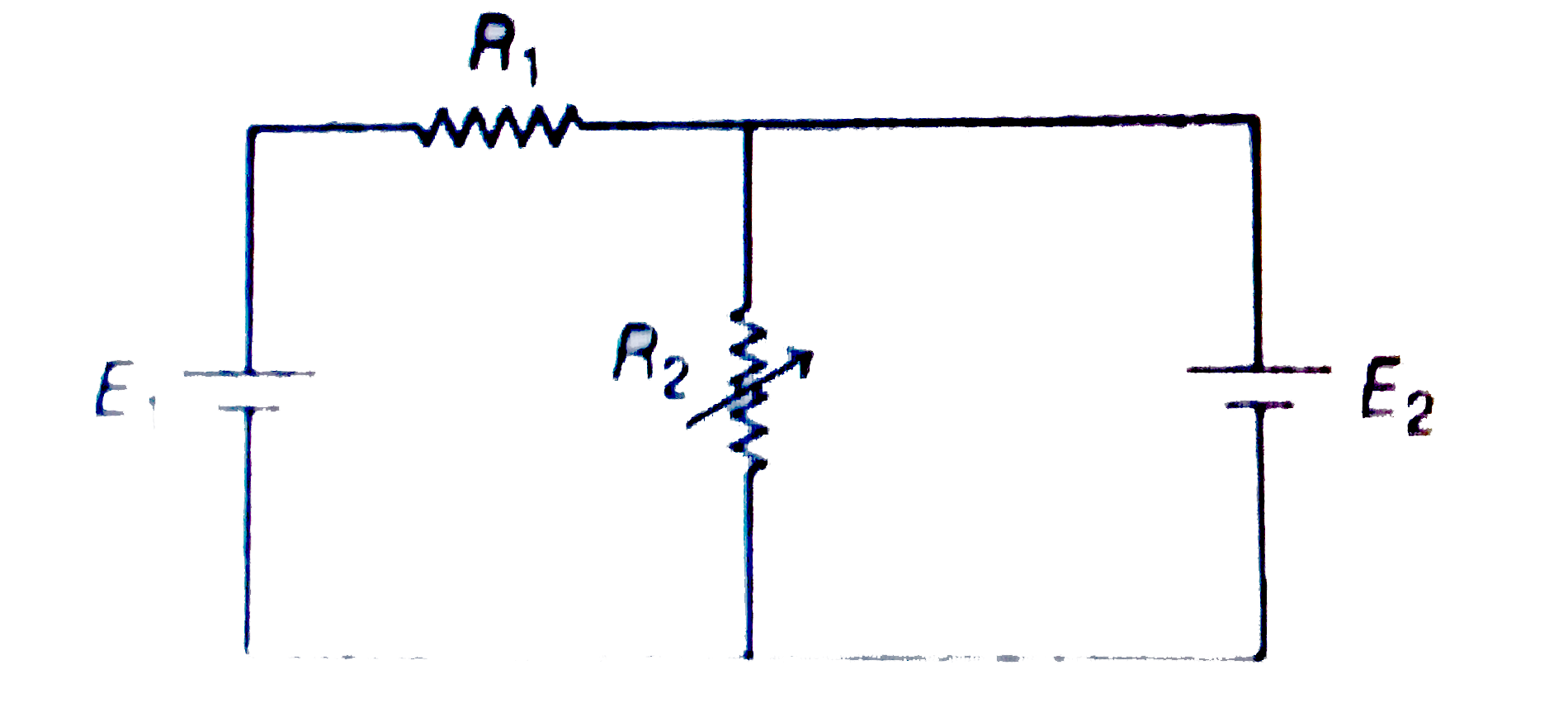
View SolutionIn the circuit shown, both cells are ideal and of fixed emf, the resistance of resistance R1 has fixed resistance and the resistance of resistor R2 can be varied (but the value of R2 is not zero). Then:
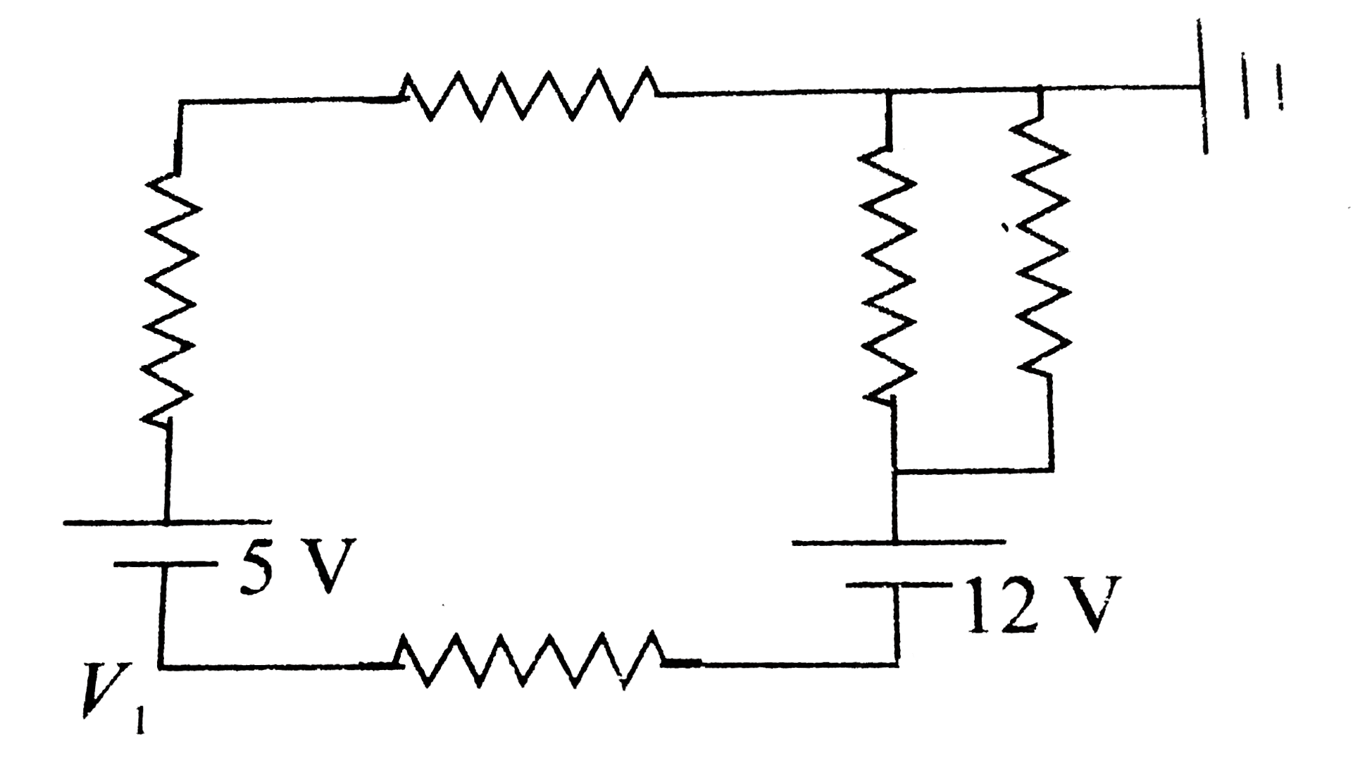
View SolutionIn the circuit shown, each resistance is 2Ω. The potential V1 is an indicated in the circuit. What is the magnitude of V1 in volt ?
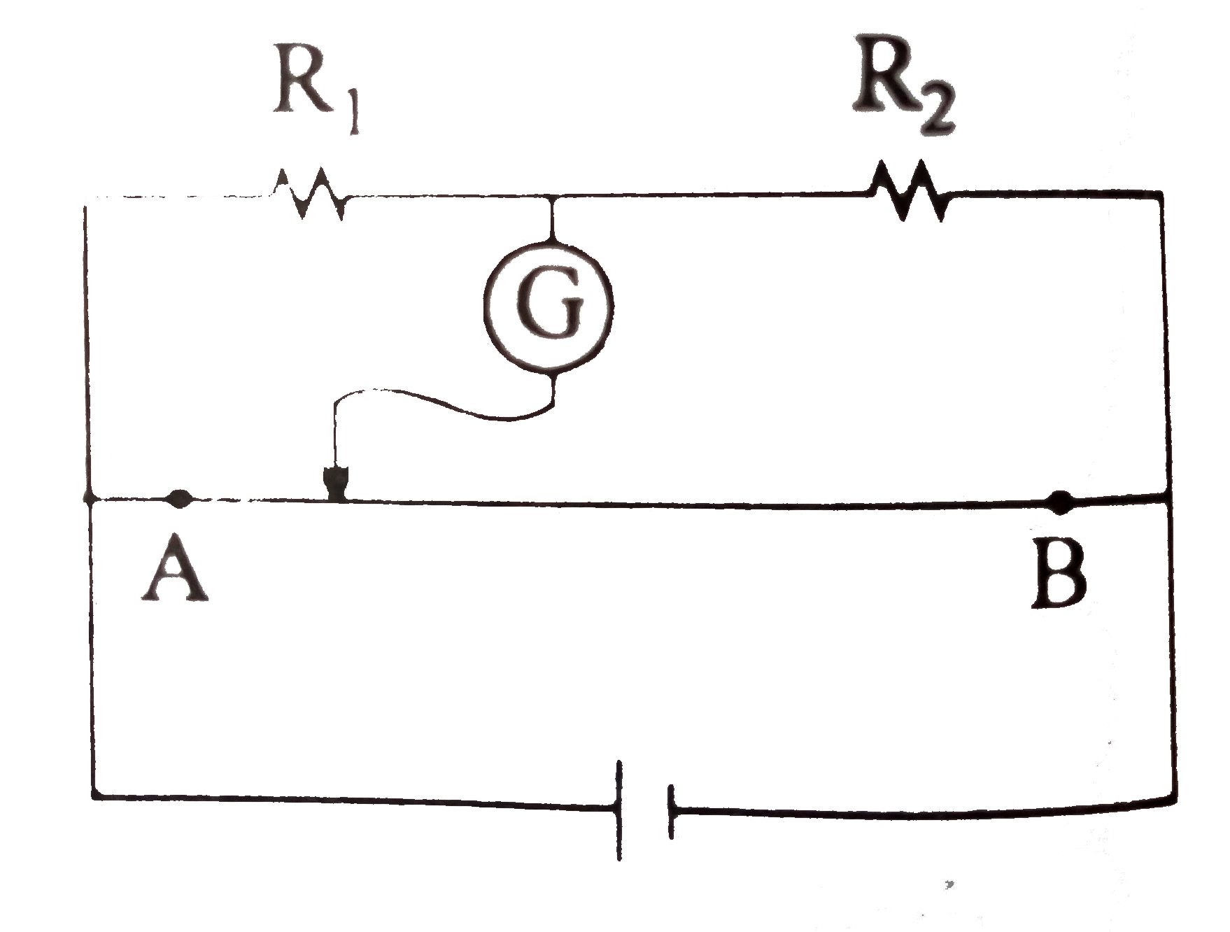
View SolutionIn the figure shown for given values of R1 and R2 the balance point for Jockey is at 40cm from A. When R2 is shunted by a resistance of 10Ω, balance shifts to 50cm. R1 and R2 are (AB=1m):
View SolutionThree resistors R1,R2 and R3 are to be combined to form an electrical circuit as shown in the figure. It is found that when R1R2andR3 are put respectively in positions A, B and C, the effective resistance of the circuit is 70 ΩWhen R2,R3andR1 are put respectively in position A, B and C the effective resistance is 35Ω and when R3,R1andR2 are respectively put in the position A, B and C, the effective resistance is 42Ω
If R1,R2 andR3are put in series, the effective resistance will be
View Solution
