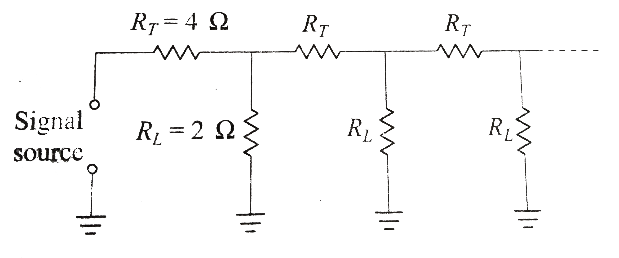
Figure shows a circuit model for the transmission of an electrical signal, such as cable TV, to a large number of subscribers. Each subscriber connects a load resistance RL between the transmission line and the ground. Assume the ground to be at zero potential and to have negligible resistance. The resistance of the transmission line between the connection points of different subscribers is modeled as the constant resistance RT. The equivalent resistance across the signal source is
10Ω
5Ω
√55Ω
√65Ω
The correct Answer is:B
b. From the hint, the equivalent resistance of the circuit is
RT+11/RL+1/Req=Req
, <br> <span class=) RT+RLReqRL+Req=Req
RT+RLReqRL+Req=Req
or RTRL+RTReq+RLReq=RLReq+R2eq
or R2eq−RTReq−RTRL=0
or Req=R±√R2T4(1)(−RTRL)2(1)
Only the positive sign is physical.
Req=12(√4RLRT+R2T+RT)
For example, if RT=1ΩandRL=20Ω,Req=5Ω.
Similar Questions
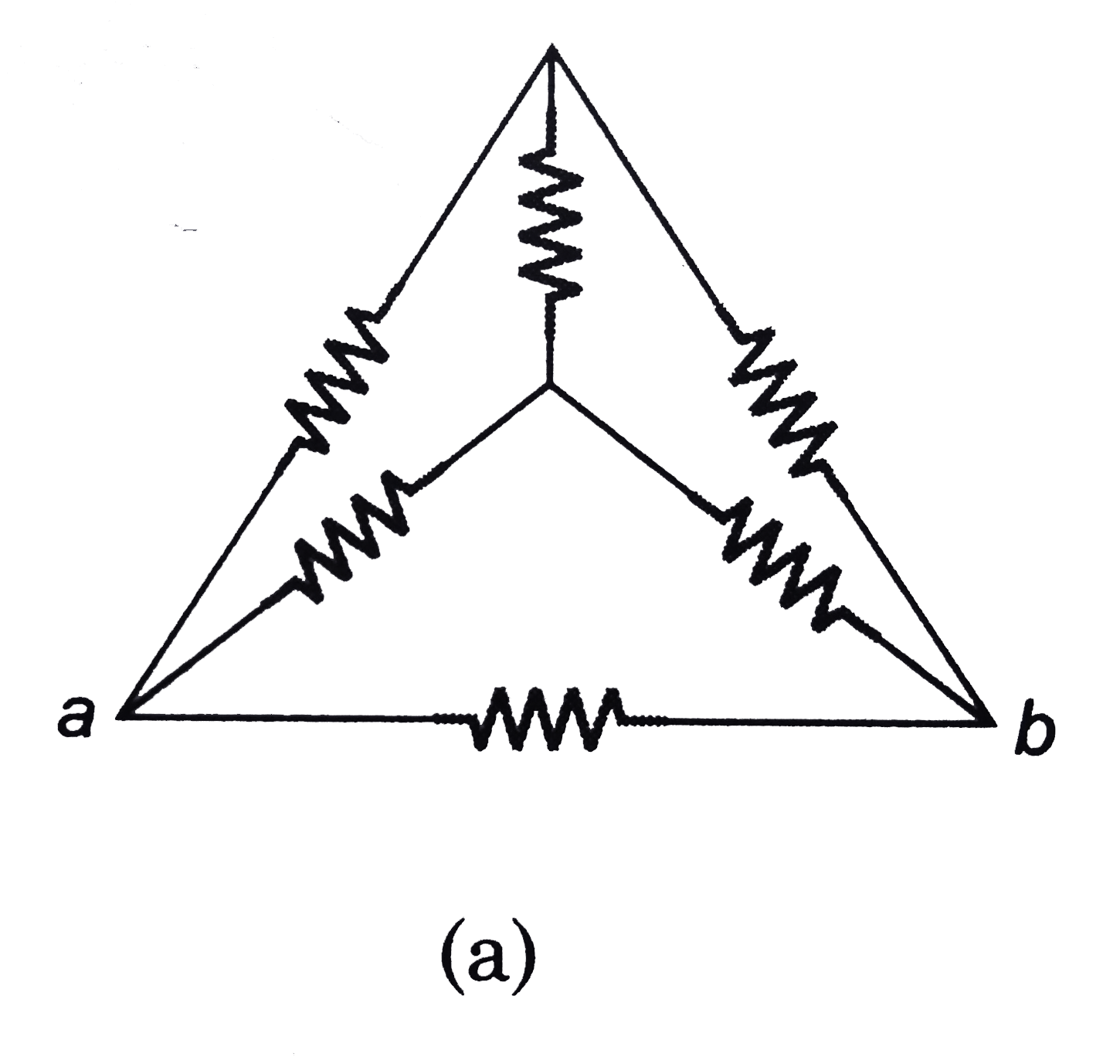
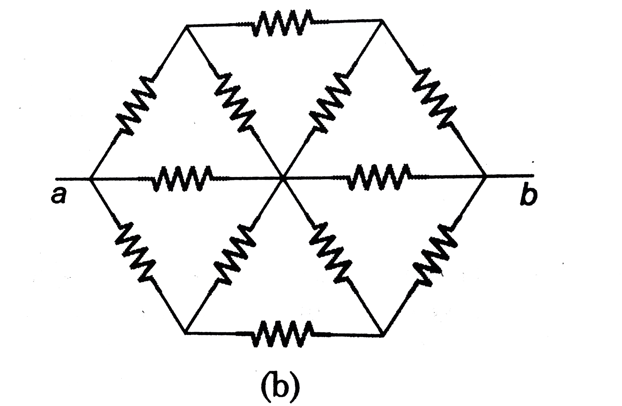
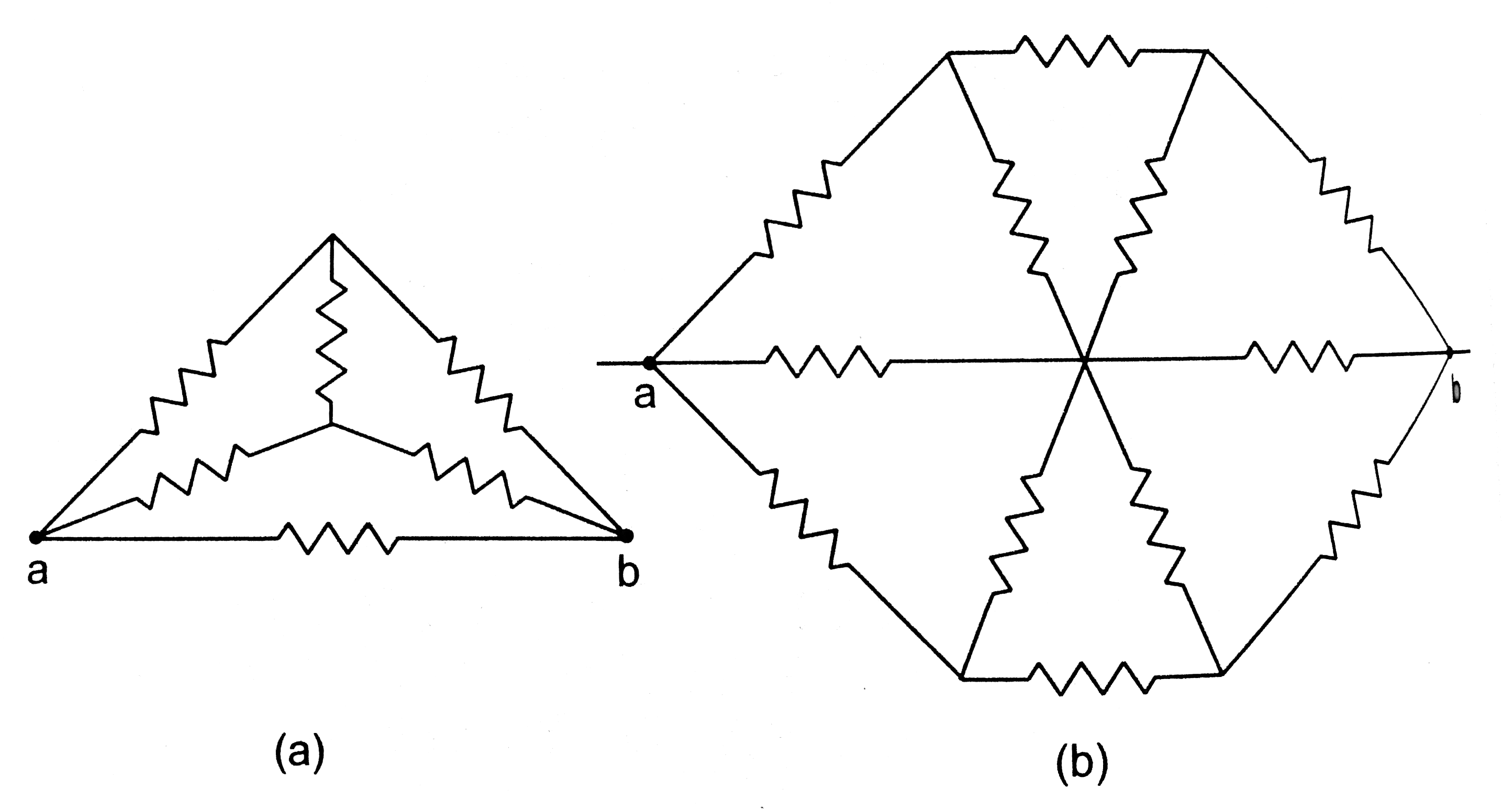
Find the equivalent resistance of the circuits shown in figure between the points a and b. Each resistor has a resistance r.
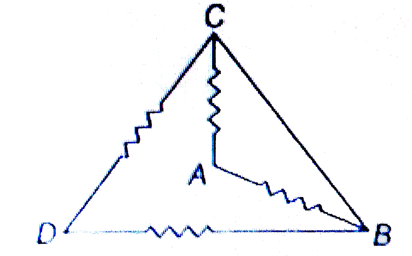
View SolutionEach resistance of the circuit shown in figure is r. The equivalent resistance between A and B is
View SolutionFind the equivalent resistance of the circuit shown in figure between the points a and b.Each resistor has a resistances r.
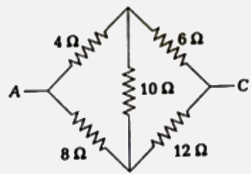
View SolutionFive resistance are connected as shown in the figure. The equivalent resistance between points A and C is
View SolutionIn the network shown in figure, each resistance is R. The equvalent resistance between points A and B is
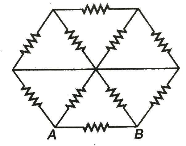
View SolutionIn the circuit shown in figure resistance of each wire is r. Net resistance across

View SolutionIn the circuit, the galvanometer G shows zero deflection. If the batteries A and b have negligible internal resistance, the value of the resistor R will be -
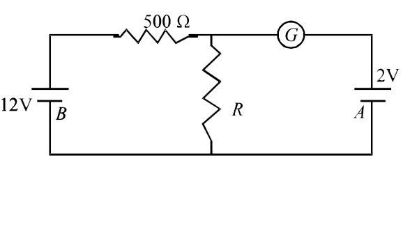
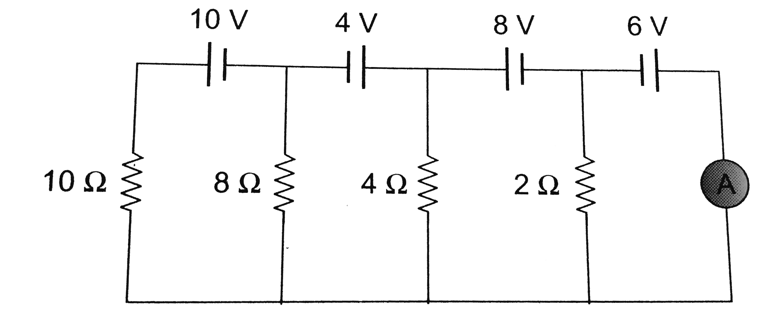
View SolutionFind the reading of the ideal ammeter connected in the given circuit. Assume that the cells have negligible internal resistance.
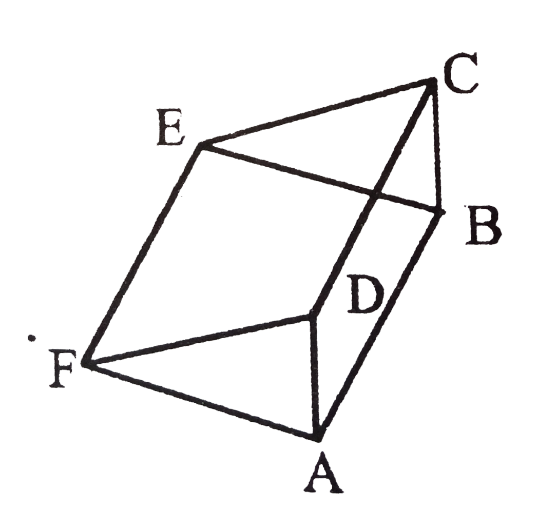
View SolutionIn the circuit shown in figure, all wires have equal resistance r. Find the equivalent resistance between A and B
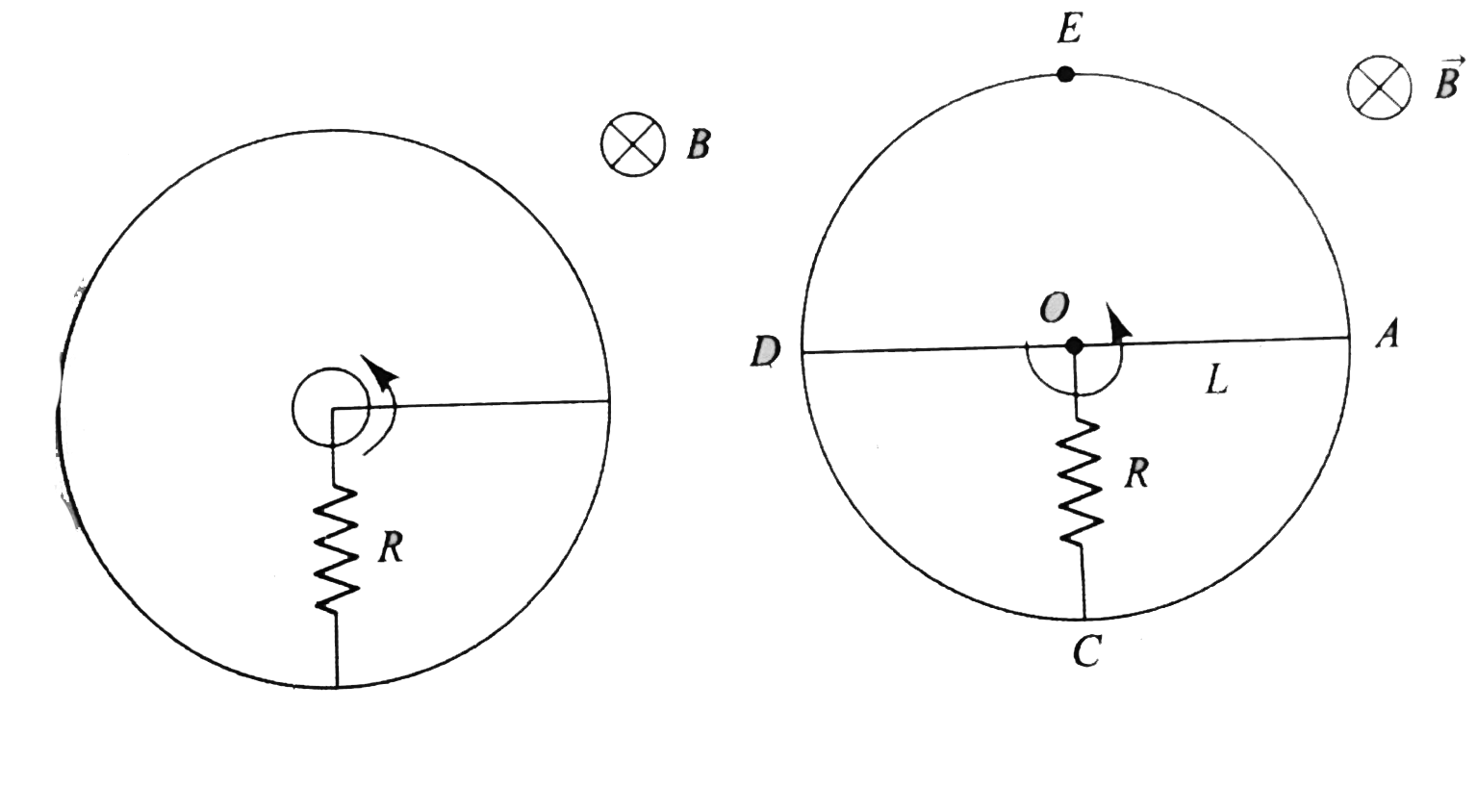
View SolutionA rod of length L and resistance r rotates about one end as shown in . Its other end touches a conducting ring of negligible resistence. A resistence R is connected between the center and periphery. Draw the electrical equivalence and find the current in resistance R. There is a uniform magnetic field B directed as shown in .
View Solution
