Two capacitros of capacity 6μF are charged to 100 V and 50 V separately and connected as shown. Now all the three switches S1,S2 and S3 are closed.
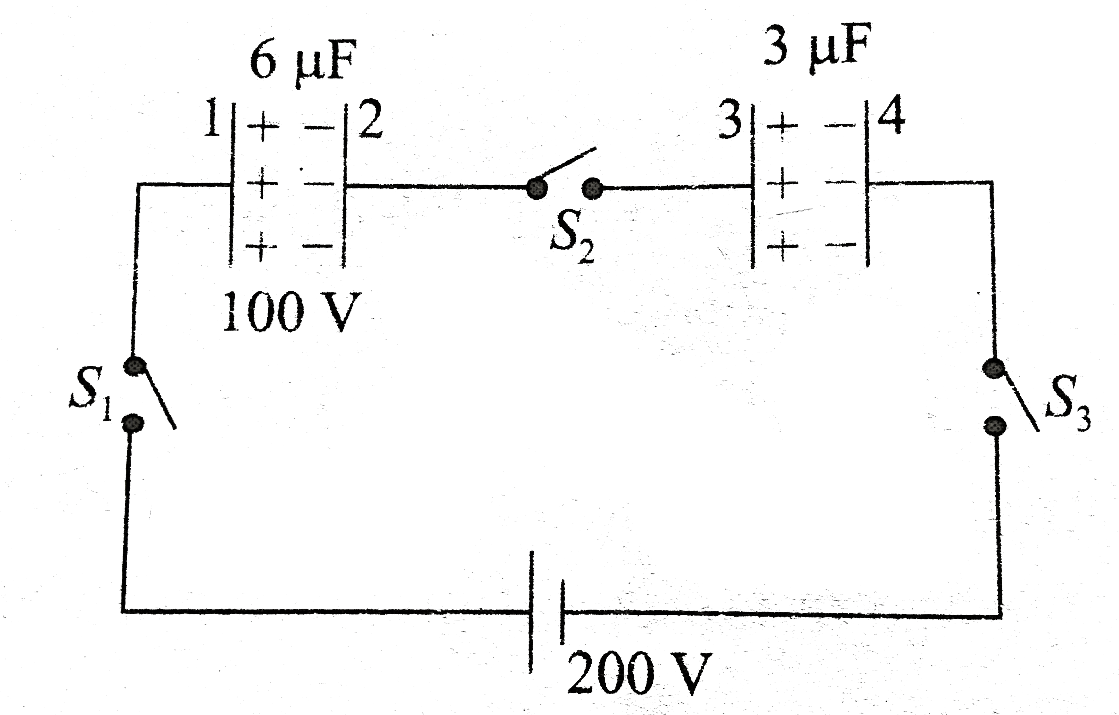
Suppose q1,q2 and q3 be the magnitudes of charge flown from switches S1,S2 and S3 after they closed. Then
q1=q3andq2=0
q1=q3=q2/2
q1=q3=3q2
q1=q2=q3
The correct Answer is:D

Plates 2 and 3 are joined together and they are neither connected to any of the terminals of the battery nor to any other source of charge. So, they jointly form an isolated system. Before closing the switches, charge are shown in Fig. After closing the switch let q charge goes from battery. Then charge on each will increase by q.
Applying Kirchhoff's voltage law, we get
200−(600+q6)−(150+q3)=0
or q=100μC
so charge on 6μF capacitor will be 70μC and 3μF capacitor will be 250μC from all the switches 100μC of charge will flow.
Topper's Solved these Questions
- MISCELLANEOUS VOLUME 3BOOK - CENGAGE PHYSICS ENGLISHCHAPTER - MISCELLANEOUS VOLUME 3EXERCISE - Interger Answer type
20 Videos
- MISCELLANEOUS VOLUME 3BOOK - CENGAGE PHYSICS ENGLISHCHAPTER - MISCELLANEOUS VOLUME 3EXERCISE - Fill in the blanks
10 Videos
- MISCELLANEOUS VOLUME 3BOOK - CENGAGE PHYSICS ENGLISHCHAPTER - MISCELLANEOUS VOLUME 3EXERCISE - Assertion and Reason Type
8 Videos
- MAGNETIC FIELD AND MAGNETIC FORCESBOOK - CENGAGE PHYSICS ENGLISHCHAPTER - MAGNETIC FIELD AND MAGNETIC FORCESEXERCISE - Multiple Correct Answer type
2 Videos
- MISCELLANEOUS VOLUME 5BOOK - CENGAGE PHYSICS ENGLISHCHAPTER - MISCELLANEOUS VOLUME 5EXERCISE - Integer
12 Videos
Similar Questions
Two capacitors of capacity 6μF and 3μF are charge 100V and 50V separately and connected as shown in Now all the three switches S1,S_(2) , and S_(3) are closed.
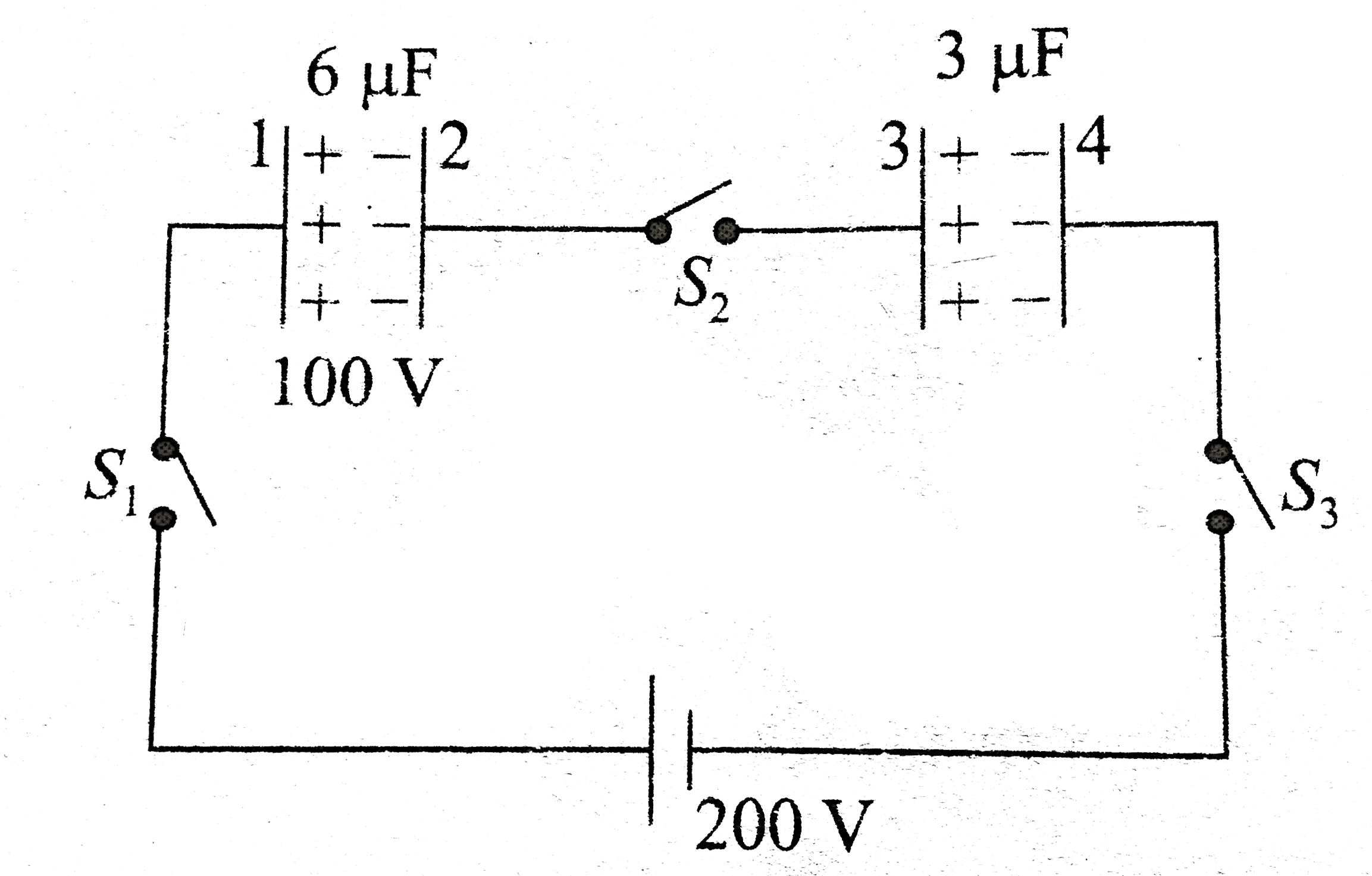
Which plates form an isolated system?
View SolutionTwo capacitros of capacity 6and3μF are charged to 100 V and 50 V separately and connected as shown. Now all the three switches S1,S2 and S3 are closed.

Charges on both the capacitors in steady state will be (on 6μF first)
View Solution
Knowledge Check
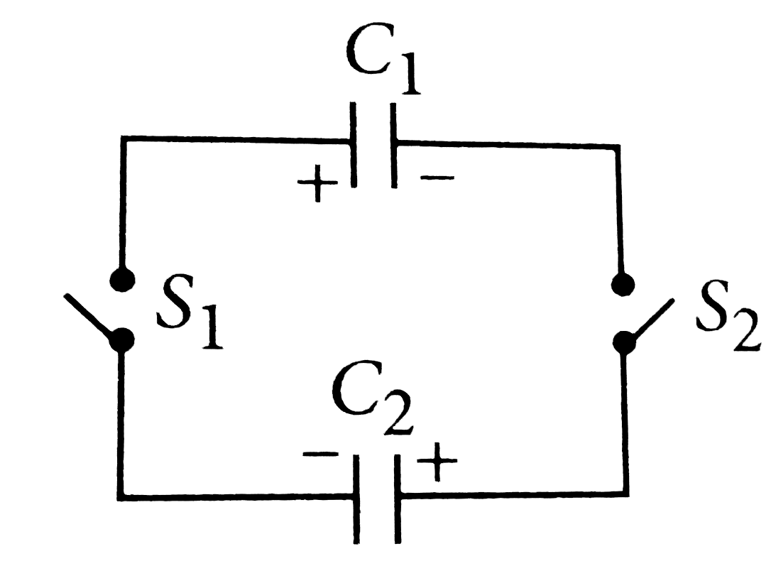
Two capacitors C1=2μF and C2=1μF are charged to same potential V=100V, but with opposite polarity as shown in the figure.
The switches S1 and S2 are closed. The ratio of final energy to the initial energy of the system is
 A1B12C19D14
Two capacitors of capacity 6μF and 3μF are charge 100V and 50V separately and connected as shown in figure. Now all the three switches S1,S2, and S3 are closed.

Charge on the 3μF capacitor in steady state willl be.
View SolutionTwo capacitors of capacity 6μF and 3μF are charge 100V and 50V separately and connected as shown in (Fig.4.201.) Now all the three switches S1,S2, and S3 are closed.
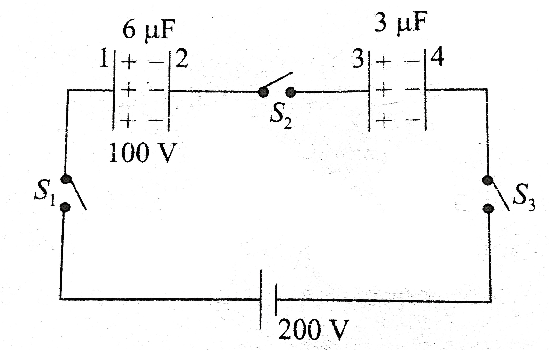
Charge on the 6μF capacitor in steady state will be.
View SolutionTwo capacitors C1 and C2 are charged to same potential V, but with opposite polarity as shown in the figure. The switches S1 and S2 are then closed

View SolutionTwo capacitors C1=4μFandC2=2μF are charged to same potential V = 500 Volt, but with opposite polarity as shown in the figure. The switches S1andS2 are closed.

View Solution(i) In an isolated system (neither connected to the terminal of a battery nor to any other source of charge e.g each) net charge remains constant.
(ii) From two terminal of a battery or from two plates of a capacitor equal and opposite charges enter or leave.
Question : Two capacitors of capacity 6μFand3μF are charged to 100 V and 50 V separatelly and connected as shown. Now all the three swiches S1S2andS3 are closed.

Which plate (s) form an isolated system .
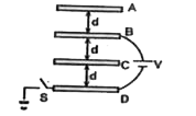
View SolutionFind the charge flown when the switch S is closed.
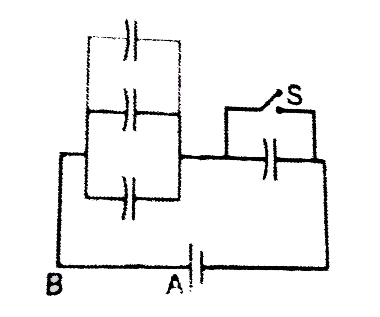
View SolutionFour capacitors of capacitance 10μF and a battery of 2V are arranged as shown. How much μC charge will flow through AB after the switch S is closed ?
View Solution
