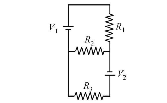
Calculate the current in bracnhes containing R1,R2andR3 in the circuit shown in
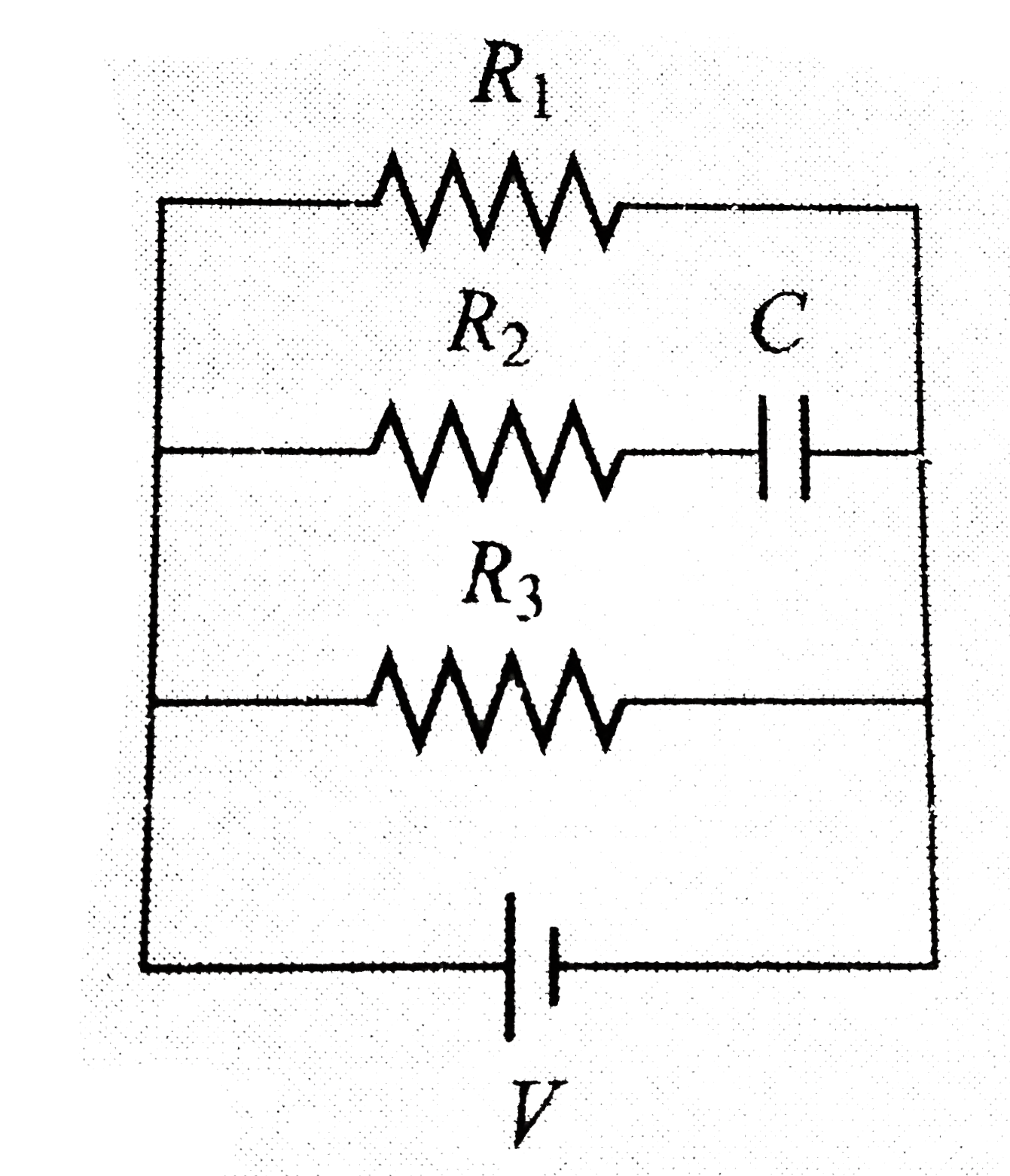
Potential difference across R1andR3 is independent of time
and remains constant. So current in them remains constant.
Veriation in current will occur only in R2. So
i1=VR1=constant,i2=i0e−t/R2C
where i0=VR2andi3=vR3
Topper's Solved these Questions
- ELECTRIC CURRENT AND CIRCUITBOOK - CENGAGE PHYSICS ENGLISHCHAPTER - ELECTRIC CURRENT AND CIRCUITEXERCISE - Solved Examples
12 Videos
- ELECTRIC CURRENT AND CIRCUITBOOK - CENGAGE PHYSICS ENGLISHCHAPTER - ELECTRIC CURRENT AND CIRCUITEXERCISE - Exercise 5.1
28 Videos
- ELECTRIC CURRENT & CIRCUITSBOOK - CENGAGE PHYSICS ENGLISHCHAPTER - ELECTRIC CURRENT & CIRCUITSEXERCISE - Kirchhoff s law and simple circuits
15 Videos
- ELECTRIC FLUX AND GAUSS LAWBOOK - CENGAGE PHYSICS ENGLISHCHAPTER - ELECTRIC FLUX AND GAUSS LAWEXERCISE - MCQ s
38 Videos
Similar Questions
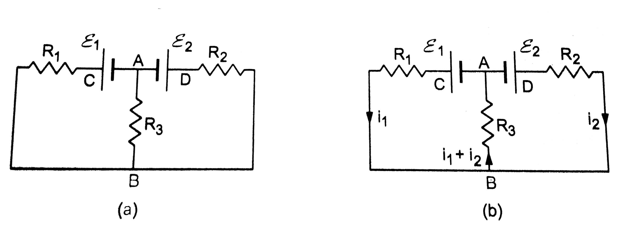
Find the currents going through the three resistors R1,R2 and R3 in the circuit of figure.
View SolutionThe current in the resistor R3 in the circuit as shown in the figure is

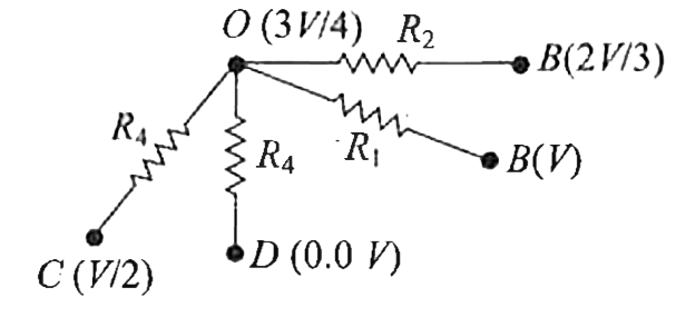
View SolutionThe circuit is shown in the following figure. The potential at points A, B, C, D and O are given. The currents in the resistance R1,R2 and R3 are in the ratio of 4:2:1. What is the ratio of resistance R1,R2,R3 and R4 ?
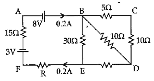
View SolutionCalculate the value of the resistance R in the circuit shown in the figure so that the current in the circuit is 0.2 A. What would be the potential difference between points B and E?
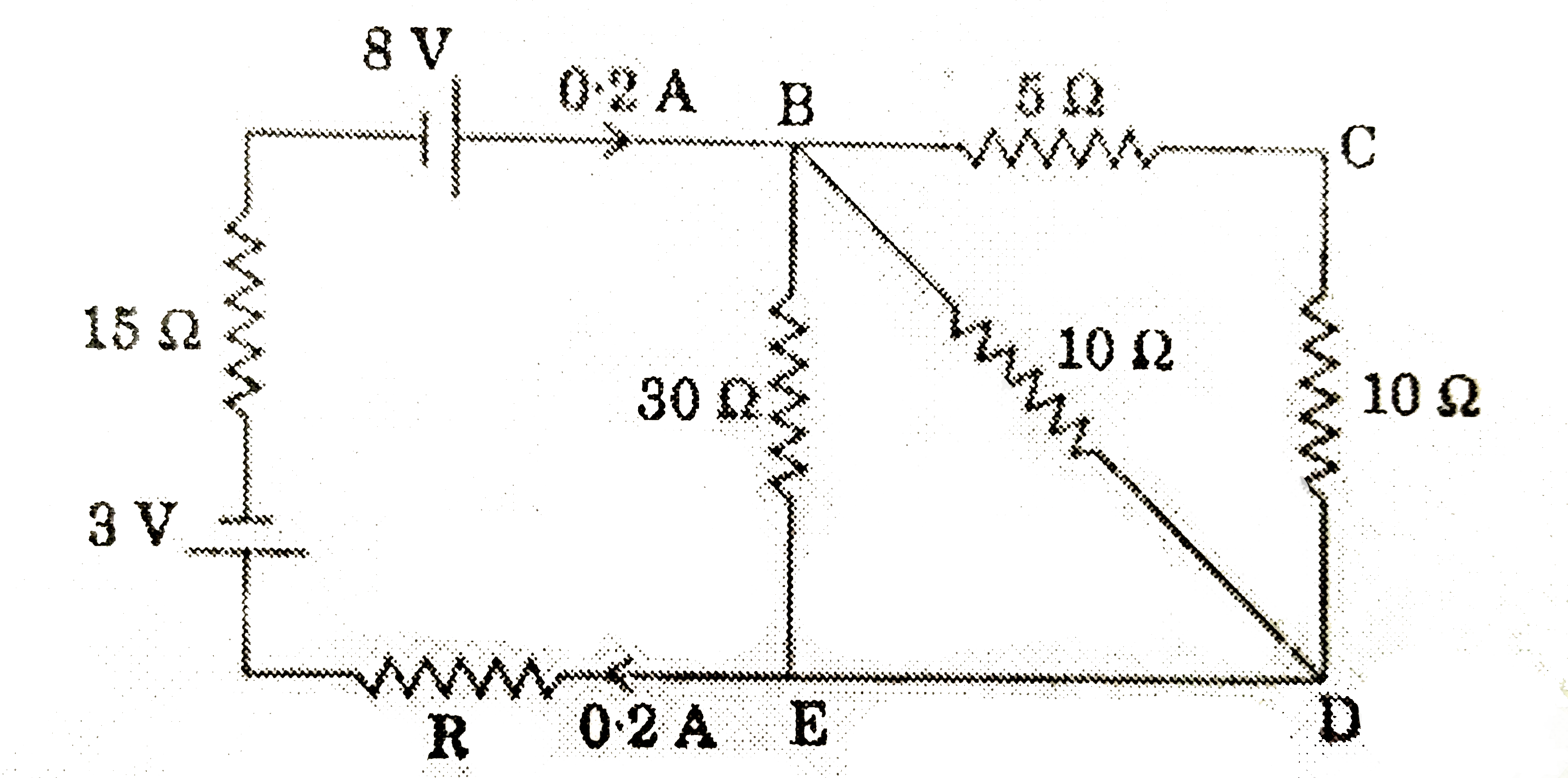
View SolutionCalculate the value of resistance R in the circuit shown in the figure so that the current in the circuits is 0.2A. What would be the potential difference between the points B and E ?
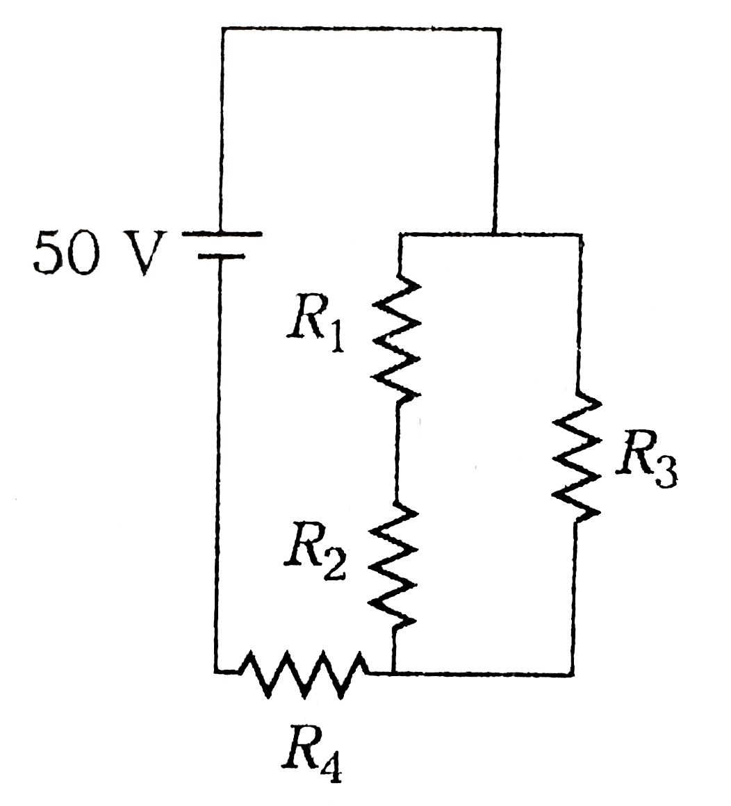
View SolutionThe potential difference in volt across the resistance R3 in the circuit shown in figure, is (R1=15Ω,R2=15Ω,R3=30Ω,R4=35Ω)
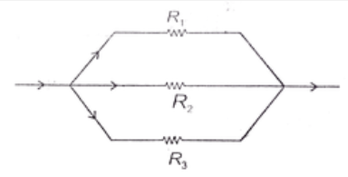
View SolutionIf in Fig. 12.12, R1=10Ω,R2=40Ω,R3=30Ω,R5=60Ω, and a 12 V battery is connected to the arrangemtn. Calculate (a) the total resistance in the circuit, and (b) the total current flowing in the circuit.
View SolutionIn the situation shown, resistance R1,R2 and R3 are in the ratio 3:2:1 , then
View SolutionIn the circuit diagram given below, three resistors R1,R2, and R3 of 5Ω,10Ω and 30Ω, respectively are connected as shown.
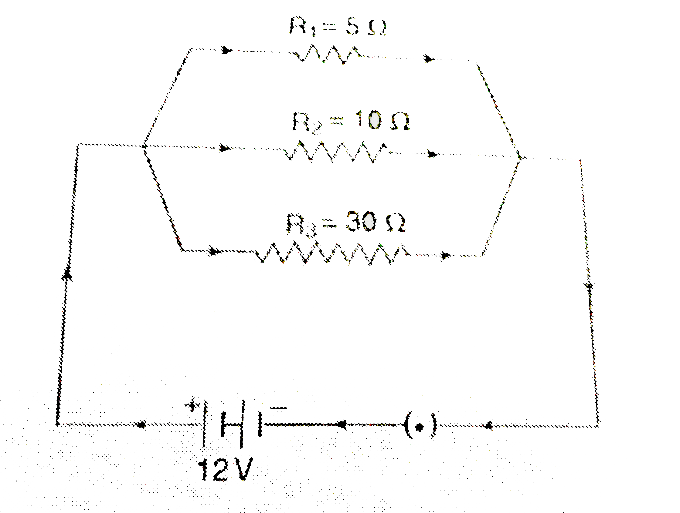
Calculate:
(a) current through each resistor.
(b) total current in the circuit.
(c) total resistance in the circuit.
View SolutionTwo ideal batteries of emf V1andV2 and three resistances R1,R2andR3 are connected as shown in the figure. The current in resistance R2 would be zero if
View Solution
