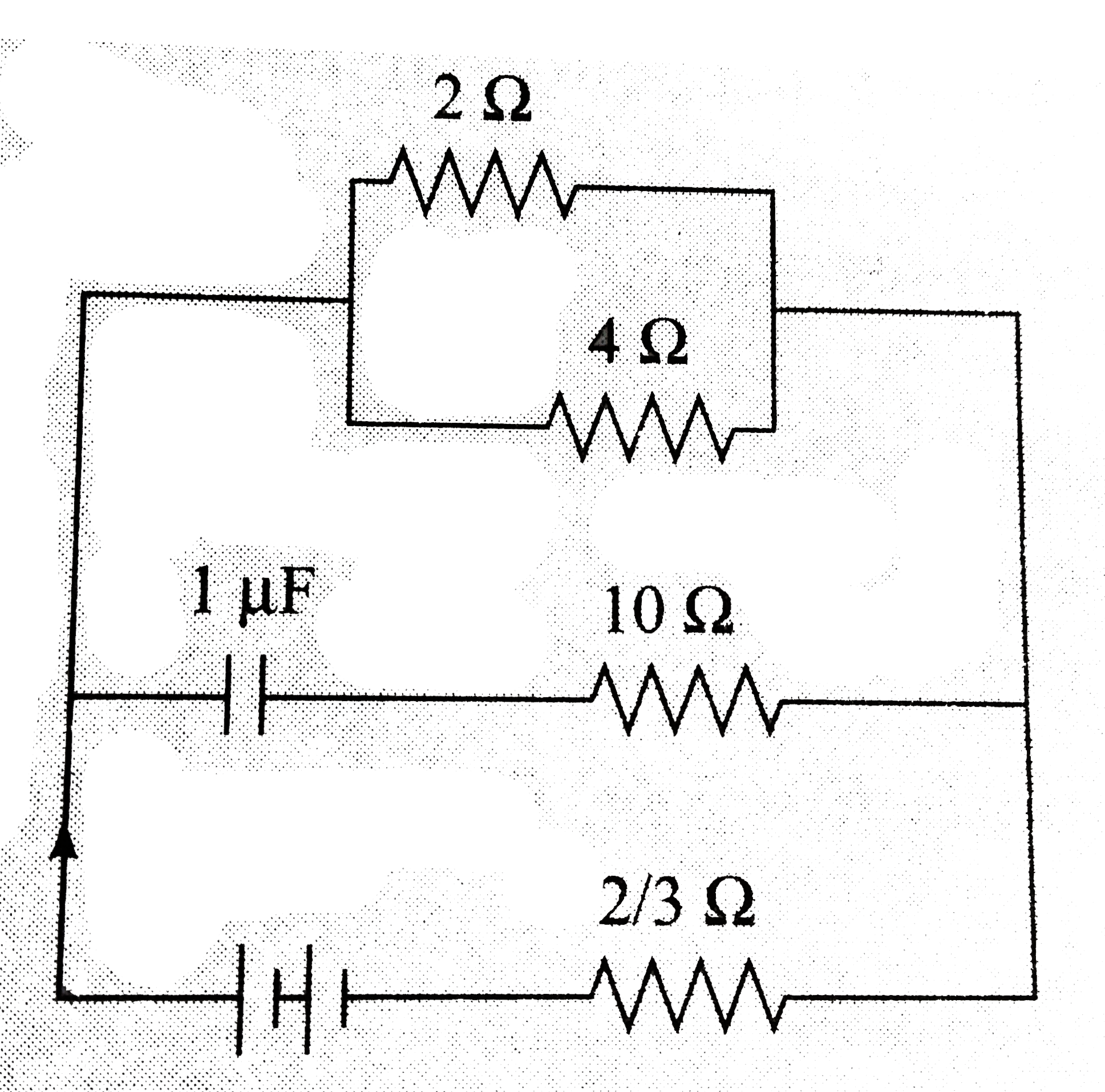
Consider the circuit shown in fig 5.174 where a battery of emf 4V and a capacitor of capacitance 1 is connected to a combination of resistacnes. Find out the stedy-state current in the battery.

Let us consider I to be the steady-state current through
the cirucuit. In the steady-state condition , current I is constant
in the circuit and the capacitor offers infinite resistance. So the
resistance becomues ineffective in the circuit. So in this
case, the euqivalent resistance of resistors that are
connected in parallel is
Therefore, the total resistance of the circuit is
Hence, the steady state current in the circuit is
Topper's Solved these Questions
- ELECTRIC CURRENT AND CIRCUITBook:CENGAGE PHYSICS ENGLISHChapter:ELECTRIC CURRENT AND CIRCUITExercise:Solved Examples
Explore 12 Videos
- ELECTRIC CURRENT AND CIRCUITBook:CENGAGE PHYSICS ENGLISHChapter:ELECTRIC CURRENT AND CIRCUITExercise:Exercise 5.1
Explore 28 Videos
- ELECTRIC CURRENT & CIRCUITSBook:CENGAGE PHYSICS ENGLISHChapter:ELECTRIC CURRENT & CIRCUITSExercise:Kirchhoff s law and simple circuits
Explore 15 Videos
- ELECTRIC FLUX AND GAUSS LAWBook:CENGAGE PHYSICS ENGLISHChapter:ELECTRIC FLUX AND GAUSS LAWExercise:MCQ s
Explore 38 Videos
Similar Questions
Knowledge Check
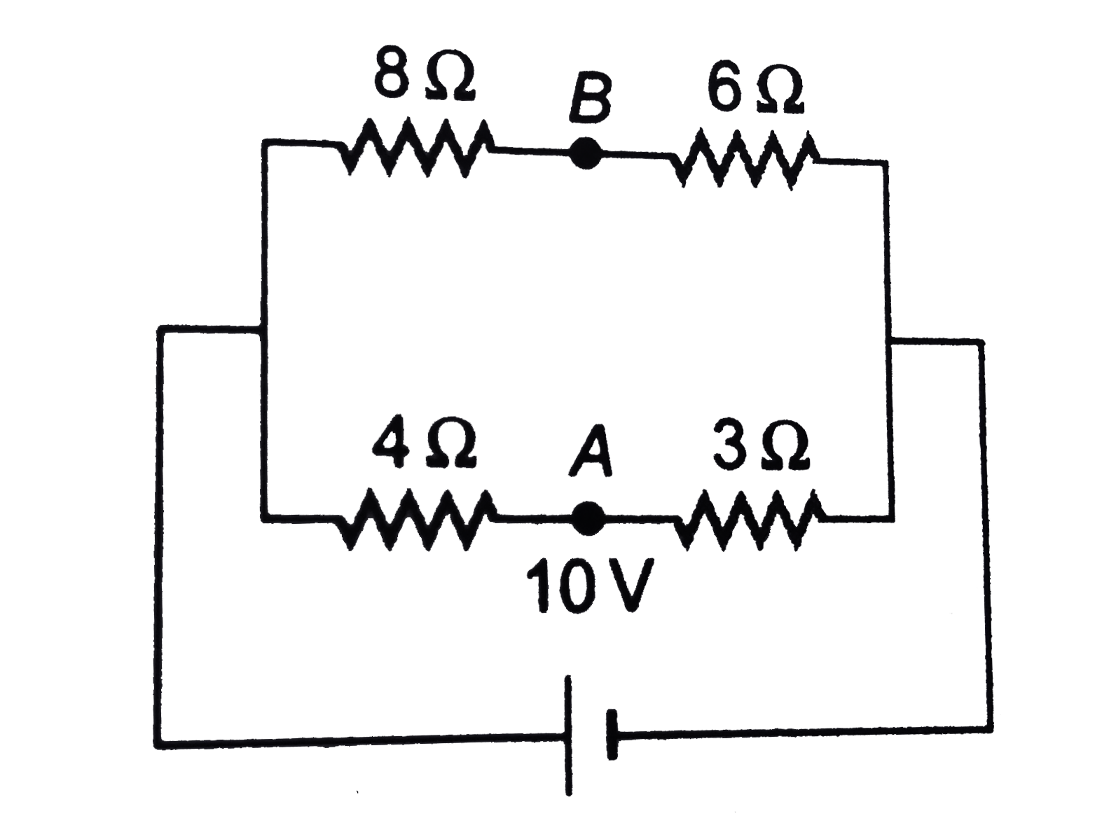
The potential difference between points A and B is
 A2B5C11D18
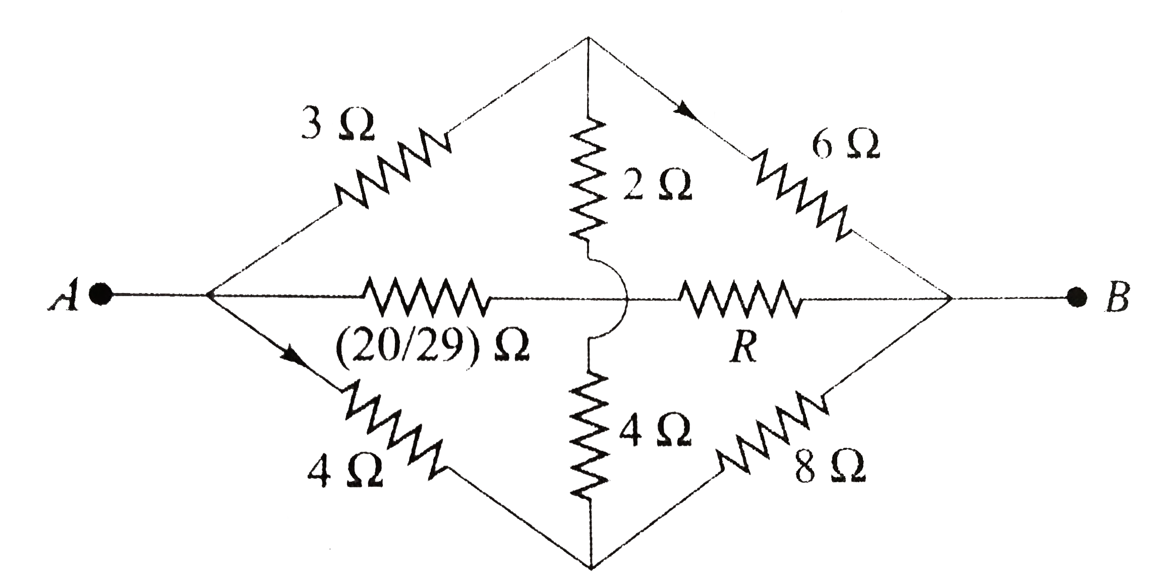
A battery of emf 2 V and initial resistance 1Ω is
connected across terminals A and B of the circuit shown
in figure
 .
.
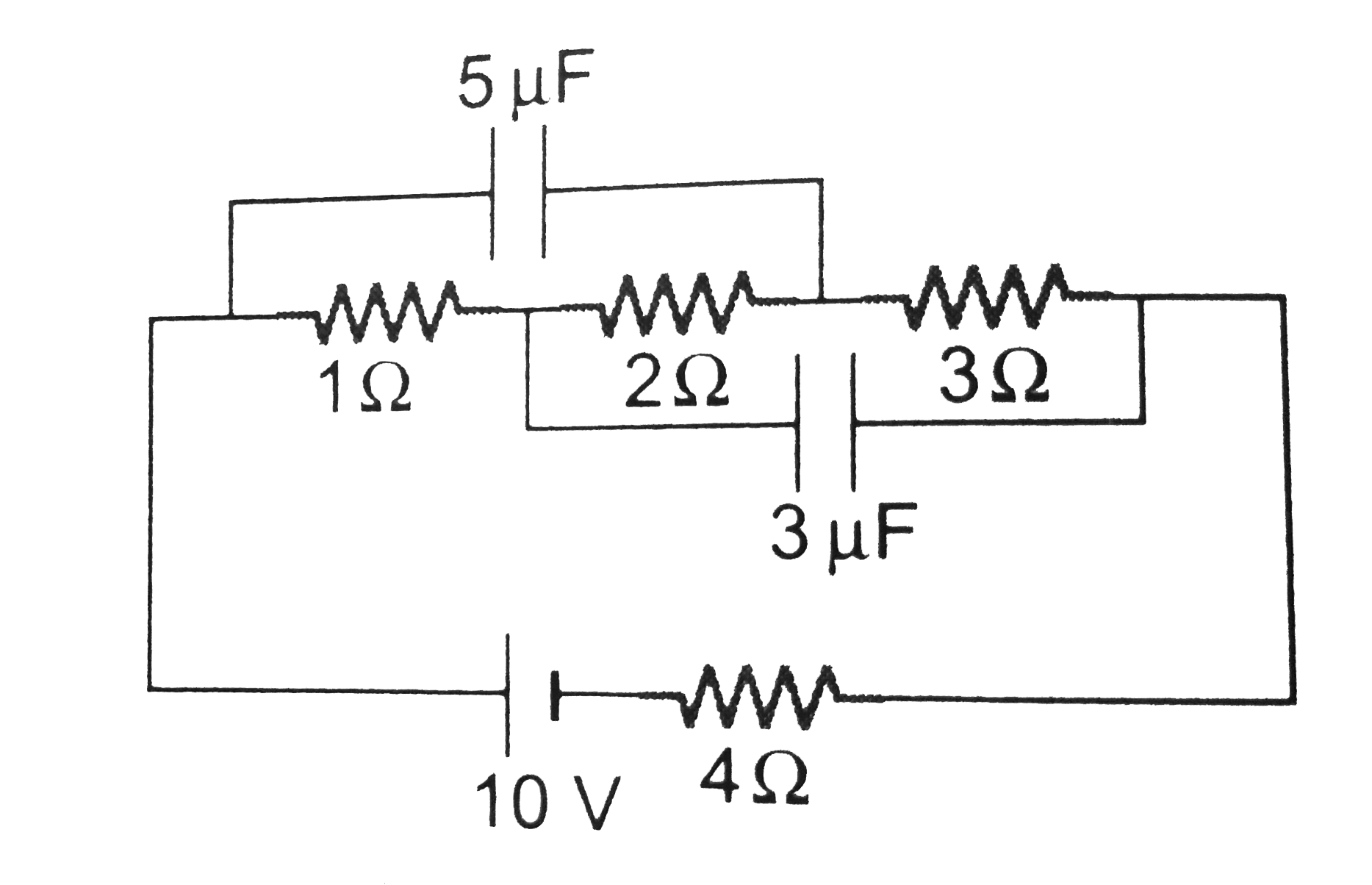
View SolutionIn the shown network, find the charges on capacitors of capacitances 5μF and 3μF, in steady state.

View SolutionFor the three circuit shown in figure across the battery capacitors are connected in some combination. Which of the following is the correct order of combination:

View SolutionAn uncharged capacitor of capacitance 100μF is connected to a battery of emf 20V at t = 0 through a resistance 10Ω, then
(ii) time at which the rate has time miximum value is
View SolutionA capacitor of capacitance C, which is initially uncharged , is connected with a battery of emf ε. Find the heat dissipated in the circuit during the process of charging .
View SolutionA circuit shown in the figure consists of a battery of emf 10V and two capacitance C1 and C2 of capacitances 1.0μF and 2.0μF respectively. The potential difference VA−VB is 5V

View SolutionA capacitor gets a charge of 60μC when it is connected to a battery of emf 12 V. Calculate the capacitance of the capactor.
View Solution