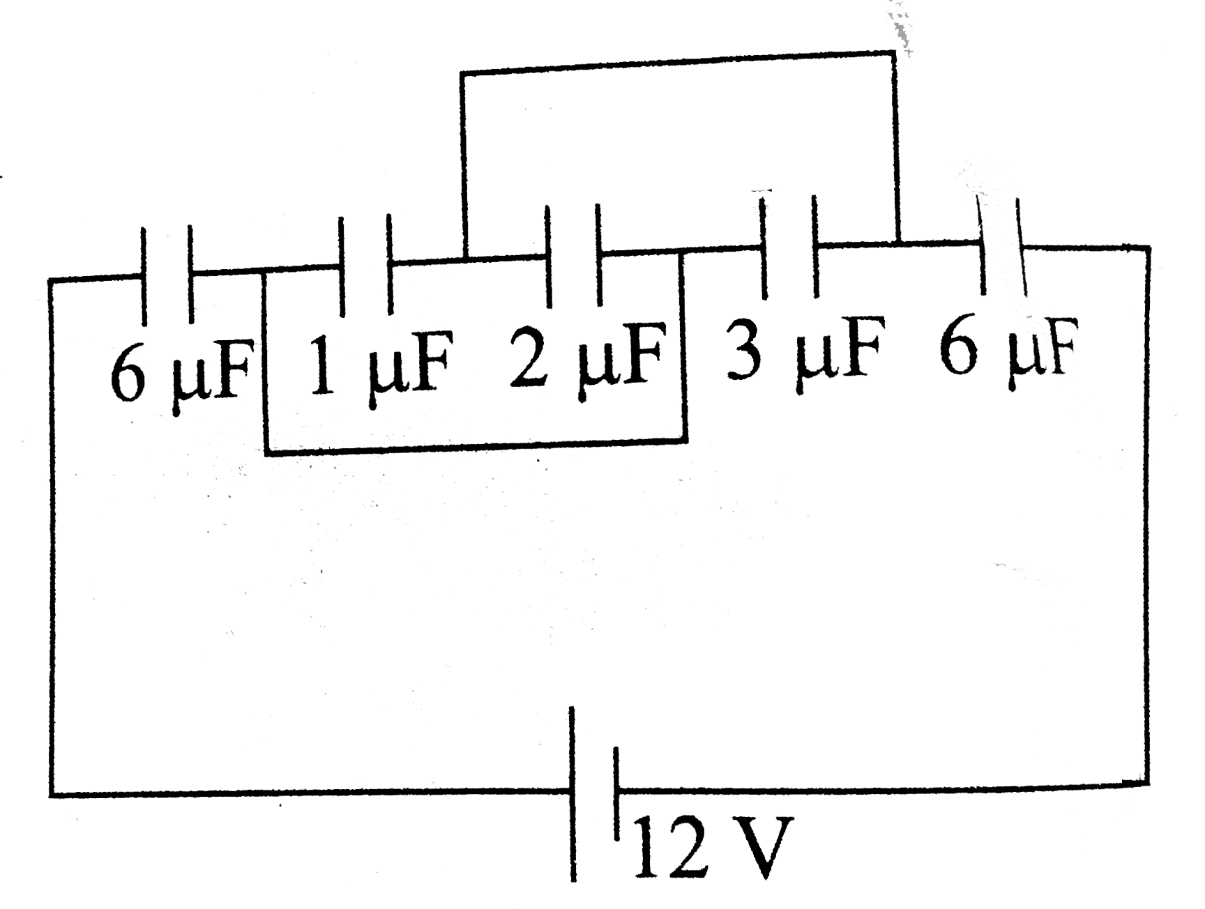
In the circuit diagram shown in Figure,
 .
.
the charge on 2μF capacitor is 8μC
the charge on each 6μF capacitor is 72μC
the pottential drop across 1μF capacitor is 4V.
the potential drop across 3μF is 4 V
The correct Answer is:A, C, D
Capacitors 1μF,2μF,And3μF are in parallel, and their total capacitance is 6μF Thus, we have three capcitors in series, each of capacitance 6μF across the 12V power supply. So potential drop across each is 123=4V. So options (a) and (b) are correct. charge on 2μF capacitor is CV=22×4=8μC. So option (c) is correct.
Charge on 6μF capacitor is 6×10⁻⁶×=24μC. So option (d) is wrong.
Thus, correct options are (a),(b), and (c).
Topper's Solved these Questions
- CAPACITOR AND CAPACITANCEBOOK - CENGAGE PHYSICS ENGLISHCHAPTER - CAPACITOR AND CAPACITANCEEXERCISE - Comprhension
35 Videos
- CAPACITOR AND CAPACITANCEBOOK - CENGAGE PHYSICS ENGLISHCHAPTER - CAPACITOR AND CAPACITANCEEXERCISE - Integer
5 Videos
- CAPACITOR AND CAPACITANCEBOOK - CENGAGE PHYSICS ENGLISHCHAPTER - CAPACITOR AND CAPACITANCEEXERCISE - Single Correct
49 Videos
- ATOMIC PHYSICSBOOK - CENGAGE PHYSICS ENGLISHCHAPTER - ATOMIC PHYSICSEXERCISE - ddp.4.3
15 Videos
- CENGAGE PHYSICS DPPBOOK - CENGAGE PHYSICS ENGLISHCHAPTER - CENGAGE PHYSICS DPPEXERCISE - subjective type
51 Videos
Similar Questions
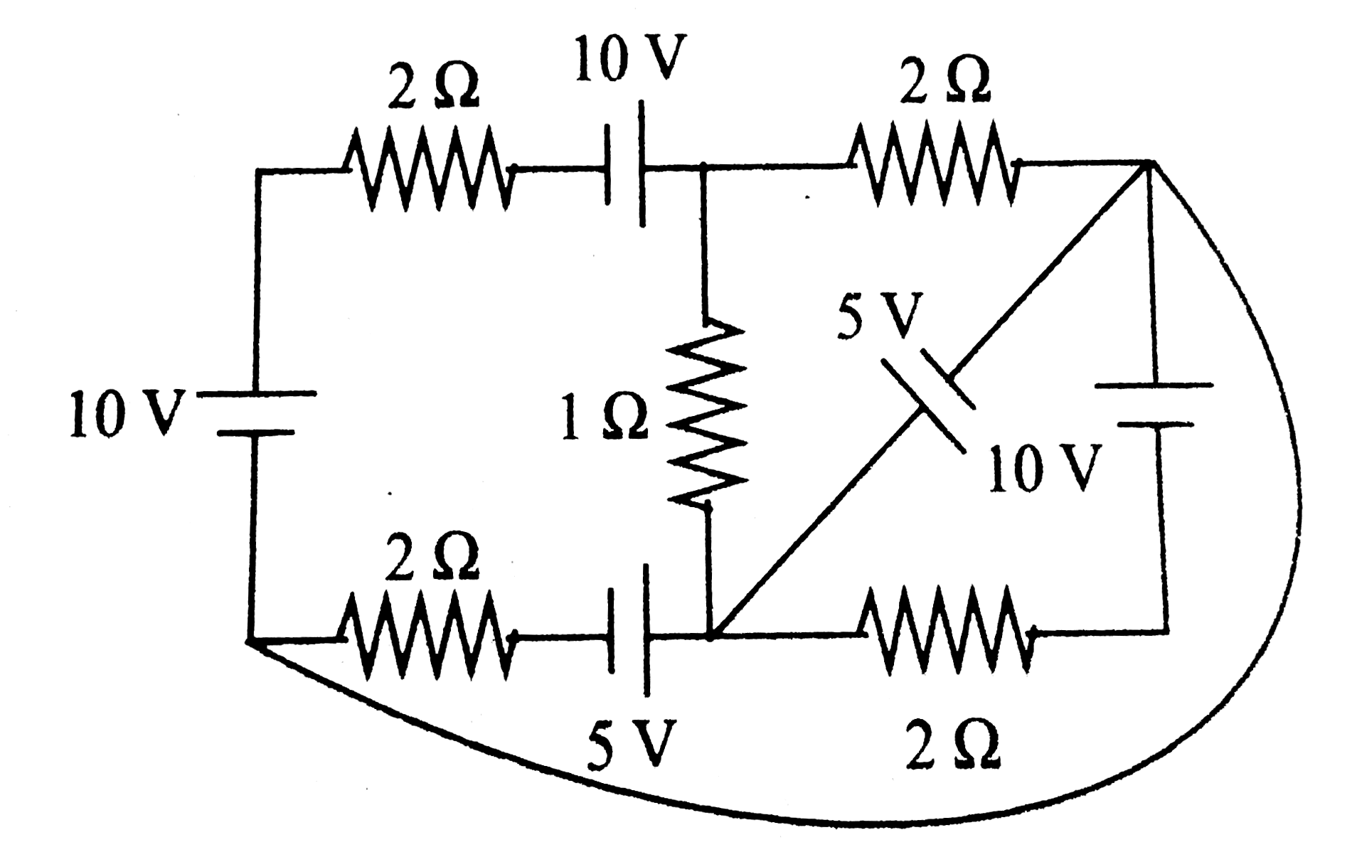
In the circuit diagram shown in find the current through the 1Ω resistor.
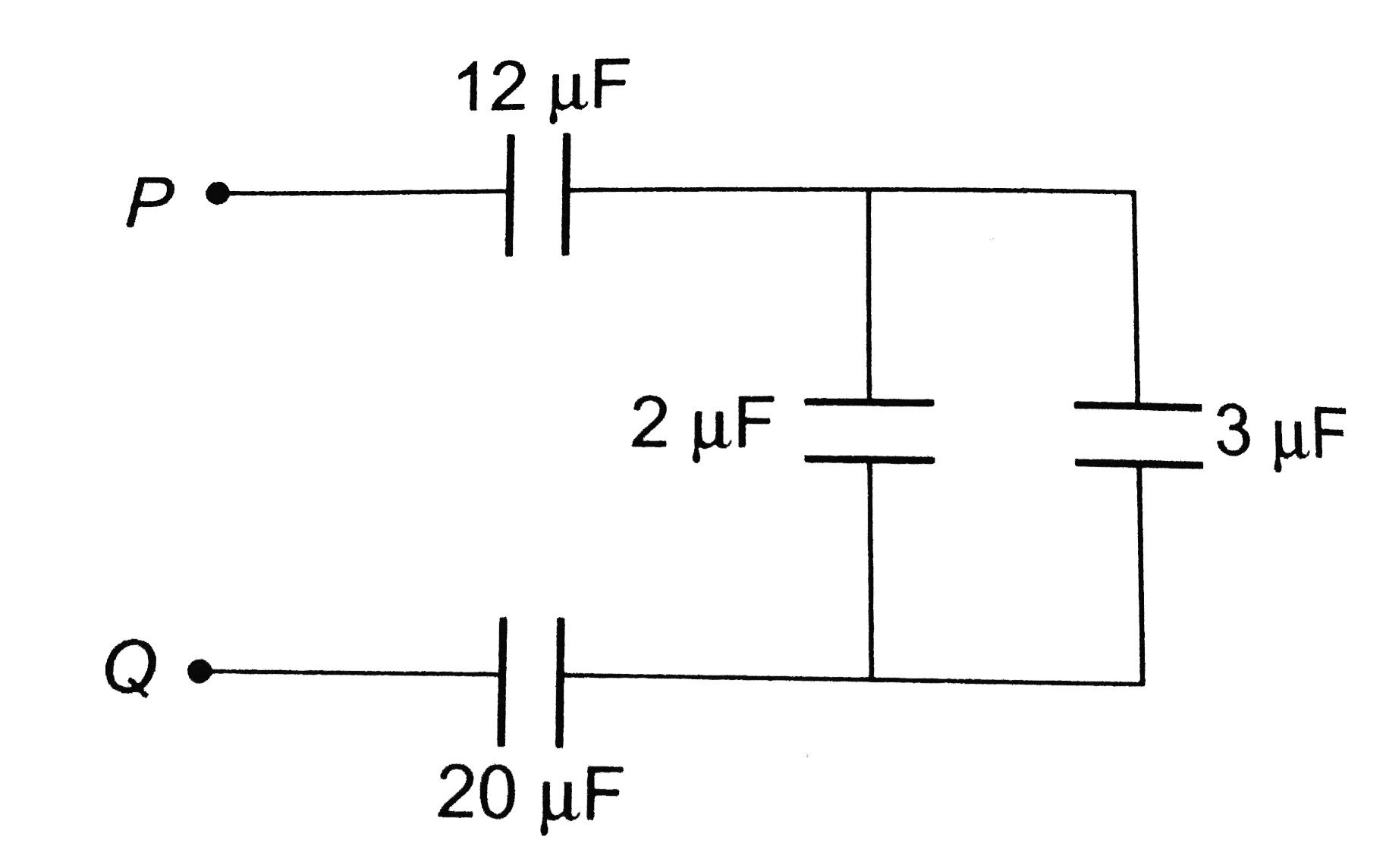
View SolutionIn the circuit diagram shown in the adjoining figure, the resultant capacitance between P and Q is
View SolutionUsing Kirchhoff ' s rules , calculate the potential difference between B and D in the circuit diagram as shown in the figure.

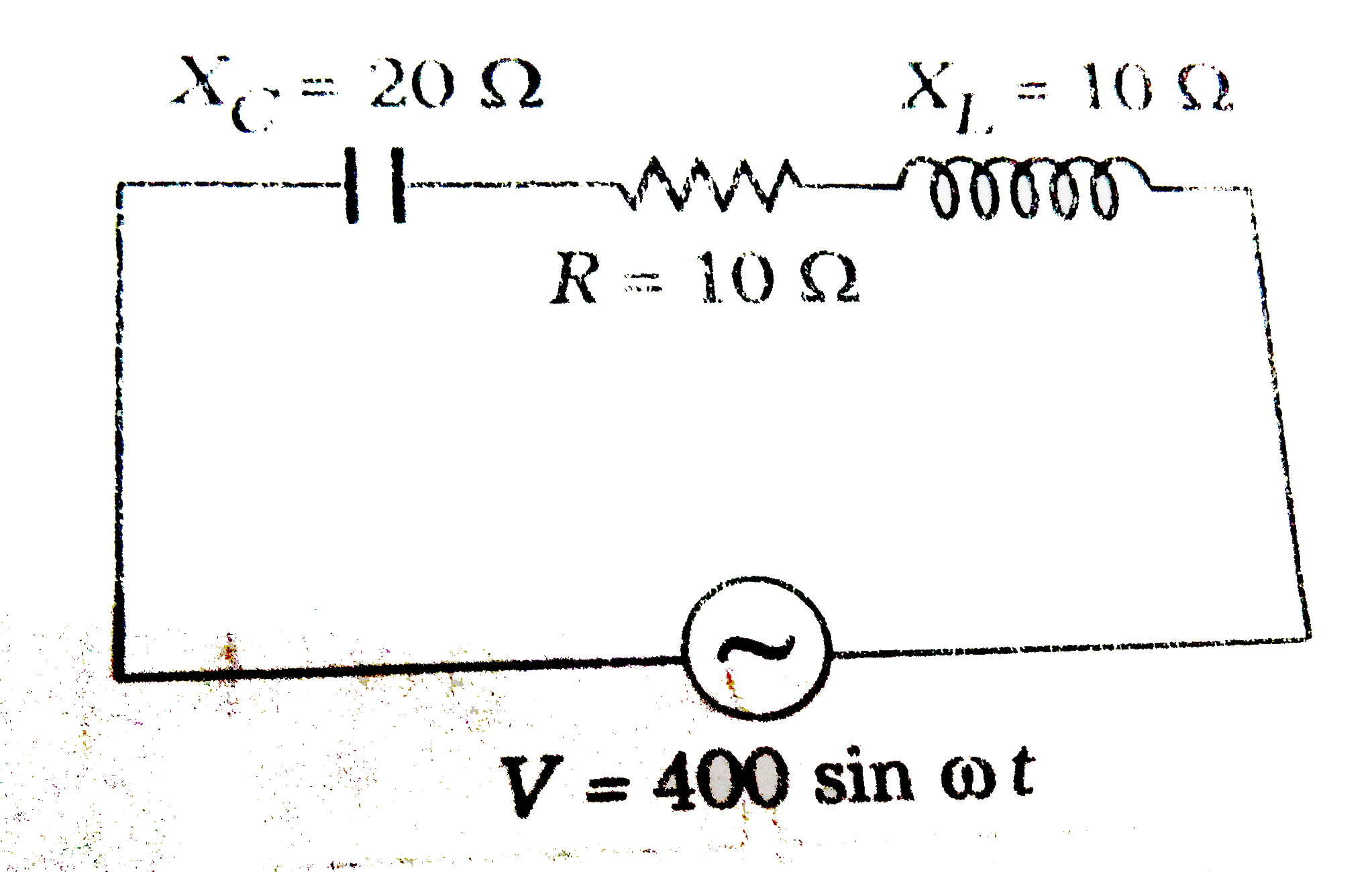
View SolutionIn the L-C-R circuit as shown in figure,
View SolutionConsider the potentiomter circuit diagram as shown in the figure. If the potentiometer wire BD has net resistance of 15Omega, the choose the correct statement
_PHY_E01_009_Q01.png)
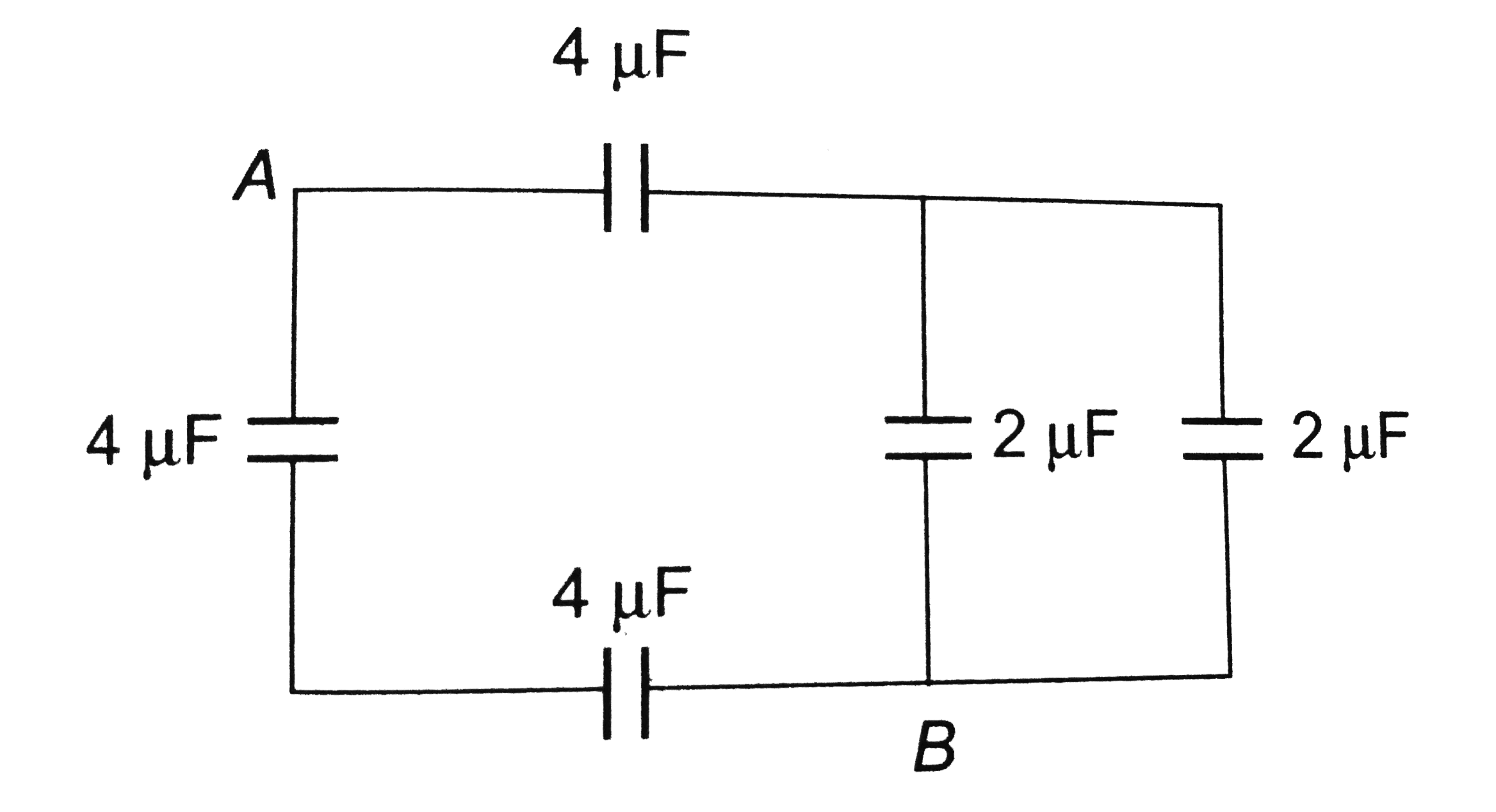
View SolutionIn the circuit as shown in the figure the effective capacitance between A and B is
View SolutionPotential difference across AB in the circuit as shown in figure.

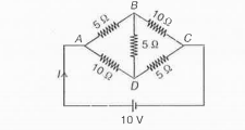
View SolutionIn the circuit shown in figure, the current / in circuit is
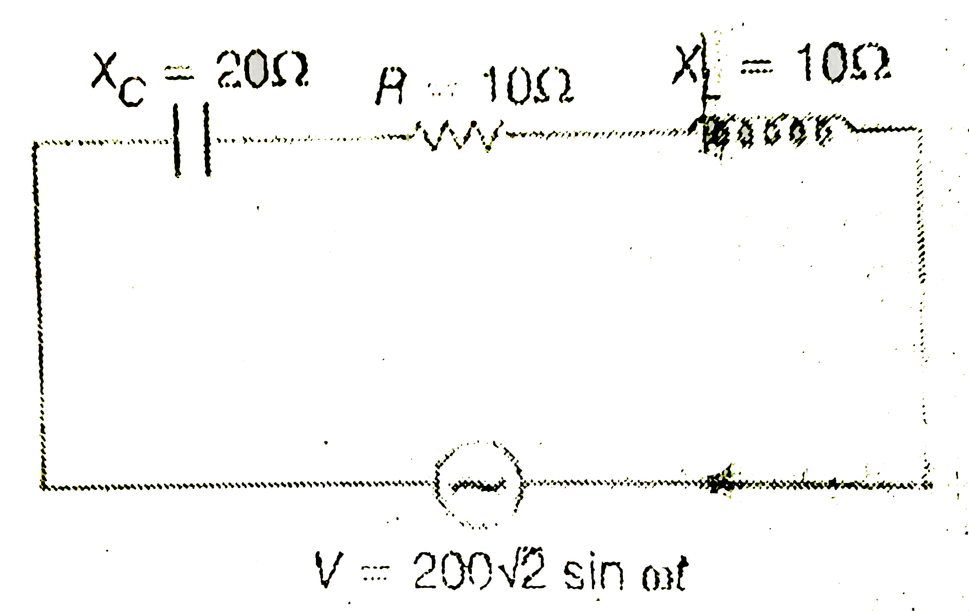
View SolutionIn LCR circuit as shown in figure
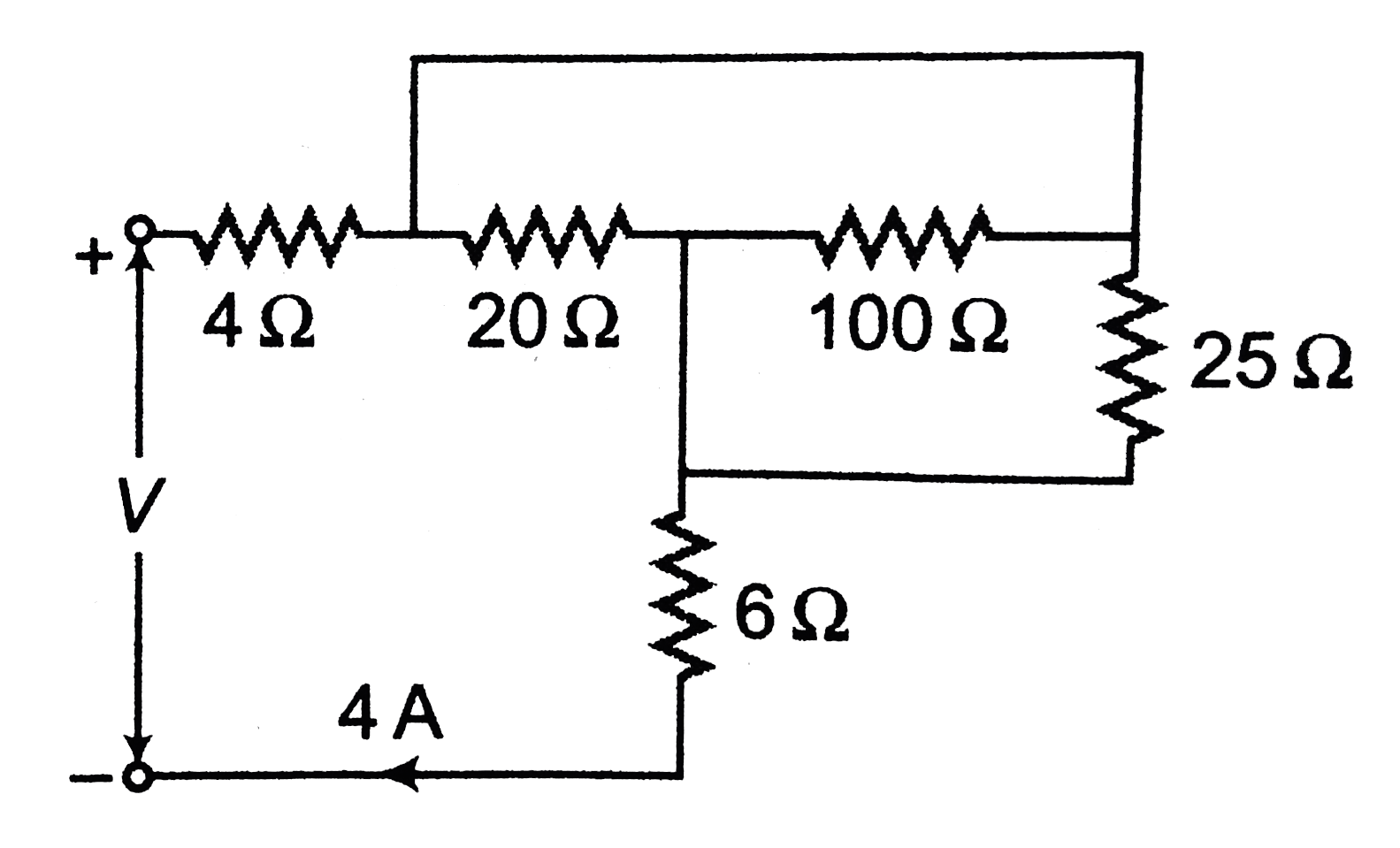
View SolutionIn the circuit shown in figure , V must be
View Solution
