PQ and MN are two parallel conductors at a distance l apart and connected by a resistance R as shown in figure. They are placed in a magnetic field B which is perpendicular to the plane of the conductors. A wire XY is placed over PQ and MN and then made to slide over PQ and MN with a velocity v. Neglecting the resistance of PQ, MN and wire XY, calculate the work done per second to slide the wire XY.
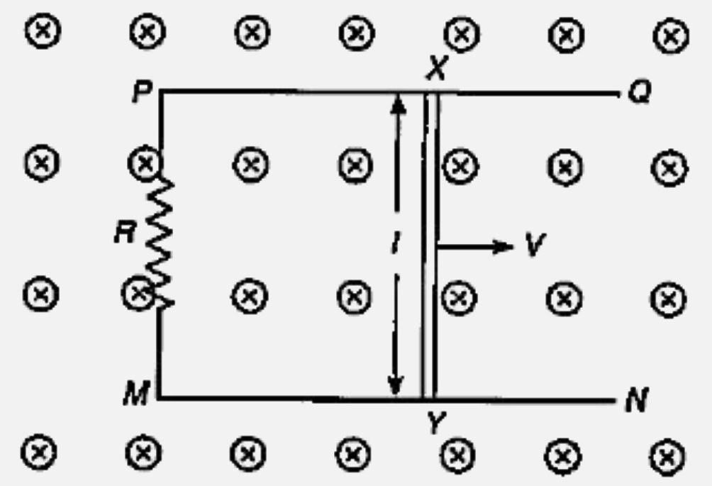
When a wire slides in a magnetic field on two conducting wires an emf is induced in the wire and current flows through the wire, hence a force acts which is opposite to the motion of the wire. Consider the diagram in which wire XY moves as shown in figure.
By Faraday.s law of induced emf, E=vBl
If resistance of loop is R, then I=vBlR
∴ Magnetic force =IBlsin90∘
=(vBlR)Bl=vB2l2R
∴ External force must be equal to magnetic force and in opposite directions.
∴ External force = vB2l2R
Due to flow of current, there is a loss of energy per unit time power in the circuit.
Power loss,
P=I2R=(vBlR)2×R=v2B2l2R2×R
P=v2B2l2R
This loss of power energy per unit time must be compensated by external agent to maintain constant speed of the rod.
Similar Questions
AB and CD are two parallel conductors kept 1 m apart and connected by a resistance R of 6Ω , as shown in figure below. They are placed in a magnetic field B=3×10⁻² T which is perpendicular to the plane of the conductors and directed into the paper. A wire MN is placed over AB and CD and then made to slide with a velocity 2ms−1 (Neglect the resistance of AB, CD, and MN.)
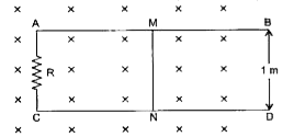
Calculate the induced current flowing through the resistor R.
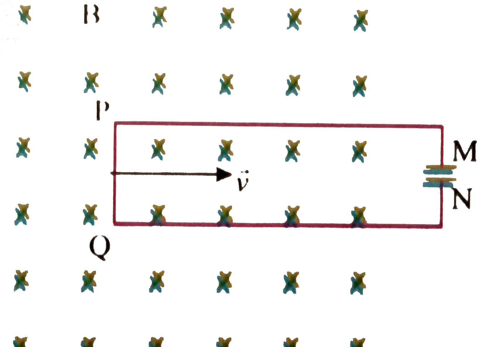
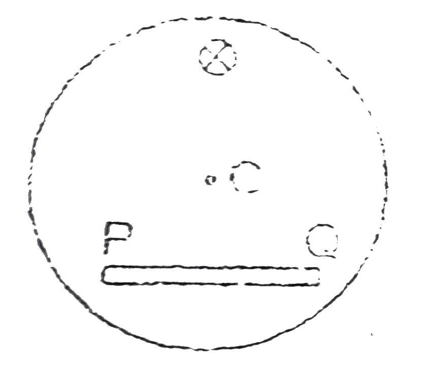
View SolutionA rod PQ is connected to the capacitor plates. The rod is placed in a magnetic field (B) directed downwards perpendicular to the plane of the paper. If the rod is pulled out of magnetic field with velocity →v as shown in Figure.
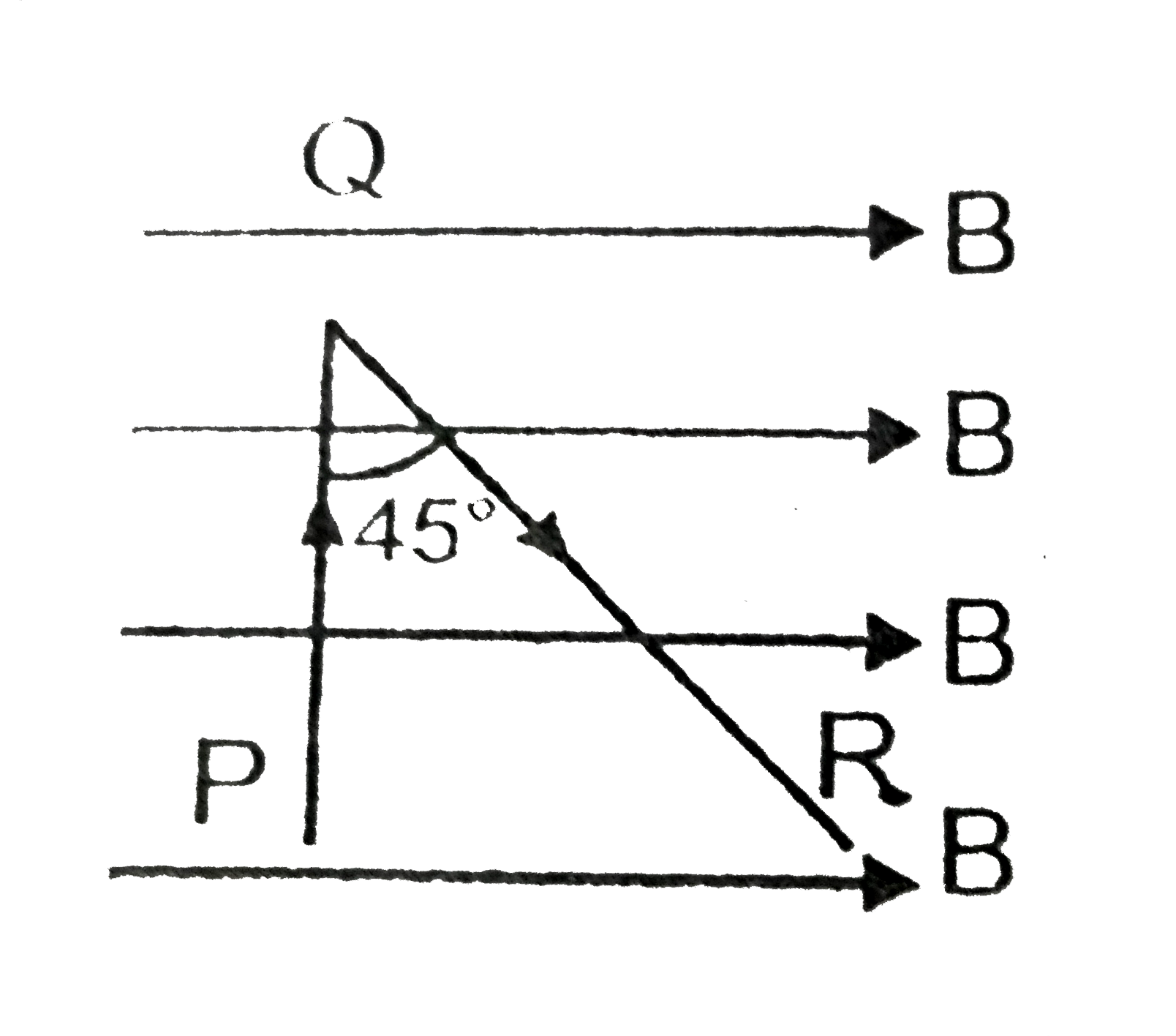
View SolutionA wire PQR carrying a current l is bent as shown in the figure. It is placed in a uniform magnetic field B. What is the ratio of magnitude of the force on PQ to that on QR ?
View SolutionIn a cylindrical region uniform magnetic field which is perpendicular to the plane of the figure is in increasing with time and a conducting rod PQ is placed in the region.If C is the centre of the circle then
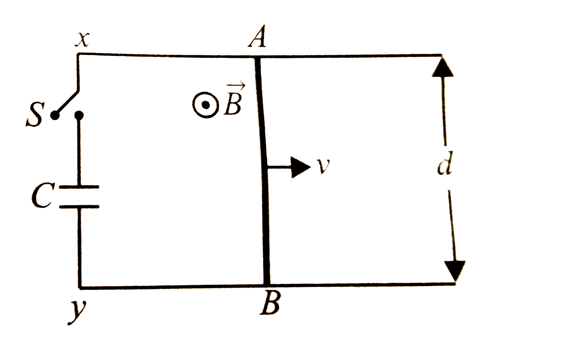
View SolutionA sliding rod AB of resistance R is shown in the figure. Here magnetic field B is constant and is out of the paper. Parallel wires have no resistance and the rod is moving with constant velocity v. The current in the sliding rod AB when switch S is closed at time t=0 is
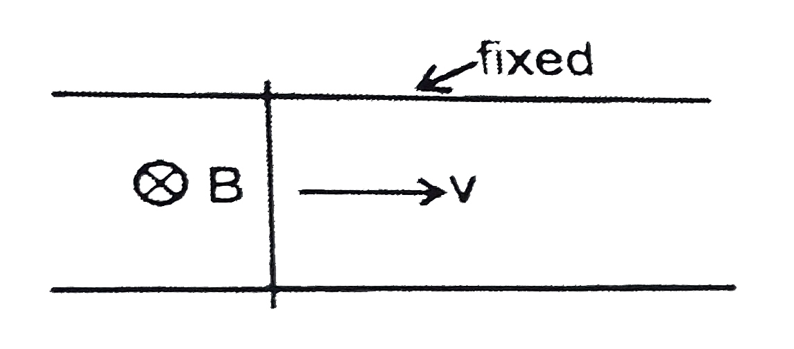
View SolutionTwo parallel fixed conducting rails are l distance apart. They are connected by a conducting wire xy. A uniform magnetic field B is applied normal to its plane. Two other rods PQ and RT(RS = ST) are moved with a constant velocity v. Resistance/ length of these two rods are λ no other wire has resistance. Then :

View SolutionFigure shows a wire of resistance R sliding on two parallel, conducting fixed thick rails placed at a separation l. A magnetic fild B exist in a direction perpendicular to the plane of the rails. The wire is moving with a constant velocity v. Find current through the wire
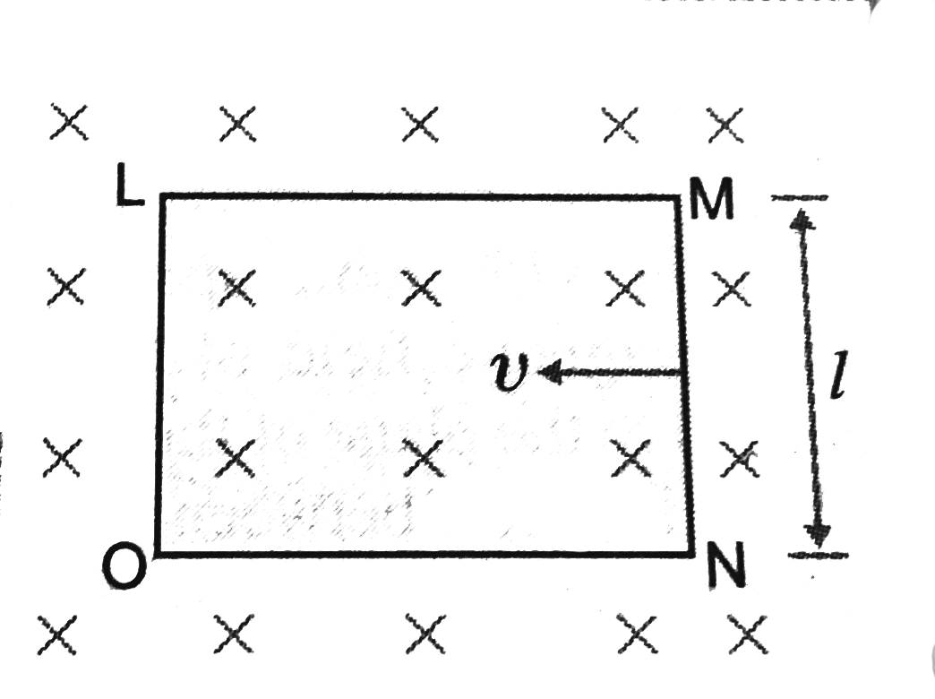
View SolutionA rectangular conductor LMNO is place in a uniform magnetic field of 0.5 T Fig. The field is directed perpendicular to the plane to the conductor. When the arm MN of length 20 cm is moved with a velocity of 10 m/s calculate the emf induced in the arm. Find the value of induced current if resistance of arm MN is 5 Ohm
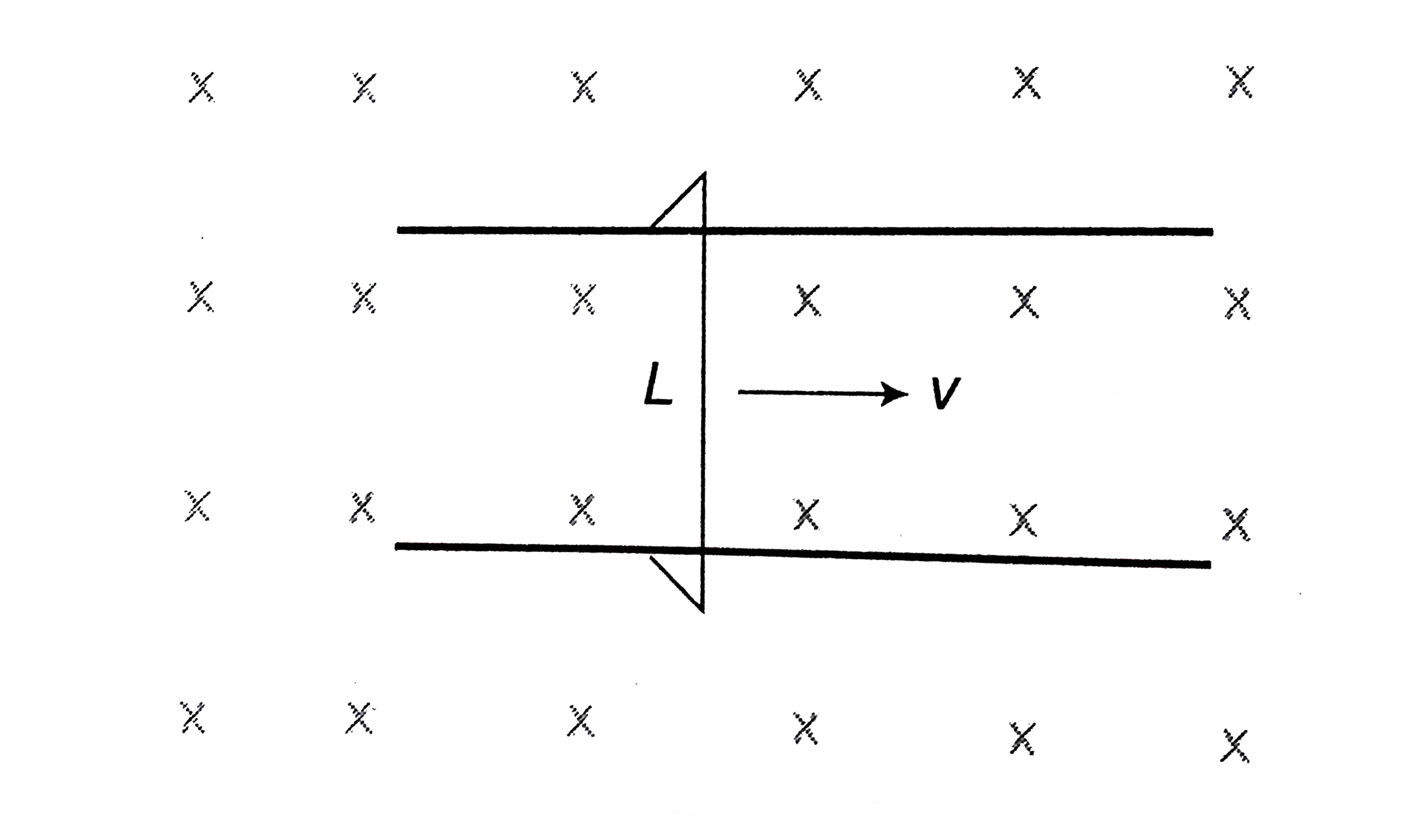
View SolutionFigure shows a wire sliding on two parallel, conducting rails placed at a separation L . A magnetic field B exists in a direction perpendicular to the plane of the rails. What force is necessary to keep the wire moving at a constant velocity V ?
View Solution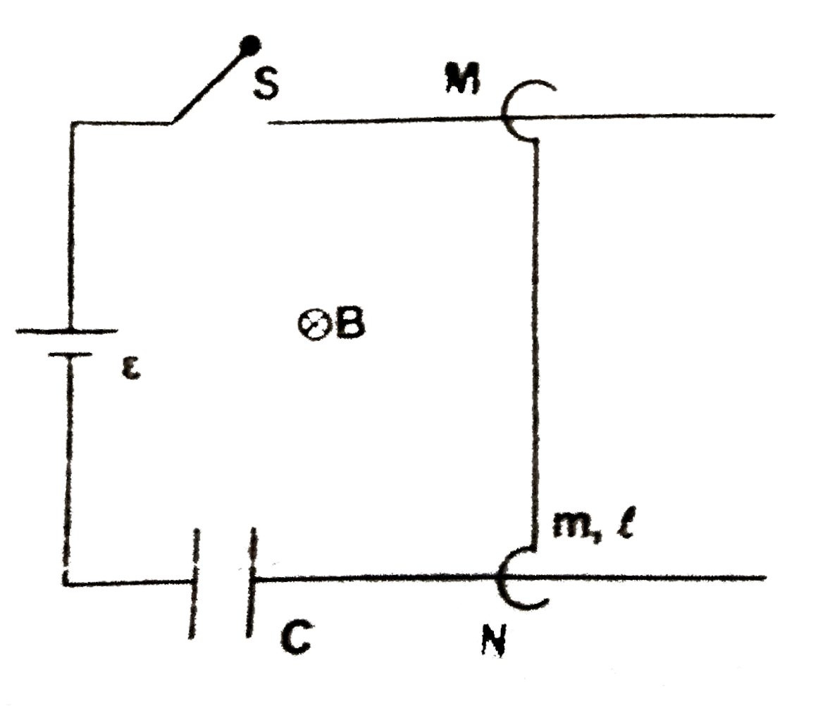
A conducting rod MN of mass m and length 'l' is placed on parallel smooth conducting rails connected to an uncharged capacitor of capacitance C and a battery of emf ε as shown. A uniform magnetic field B is existing perpendicular to the plane of the rails. The steady state velocity acquired by the conducting rod MN after closing switch S is (neglect the resistance of the parallel rails and the conducting rod)
View Solution

