The output (X) of the logic circuit shown in figure will be

A
X=¯¯¯¯¯¯¯A.¯¯¯¯¯¯B
B
X=¯¯¯¯¯¯¯¯A.B
C
X=A.B
D
X=¯¯¯¯¯¯¯¯¯¯¯A+B
Video Solution
Text Solution
The correct Answer is:C
|
Updated on:21/07/2023
Similar Questions
The outpout Y of the logic circuit shown in figure is best represented as
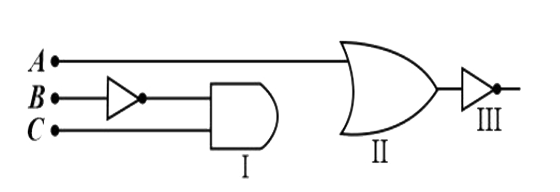 View Solution
In the two circuits shown in figure
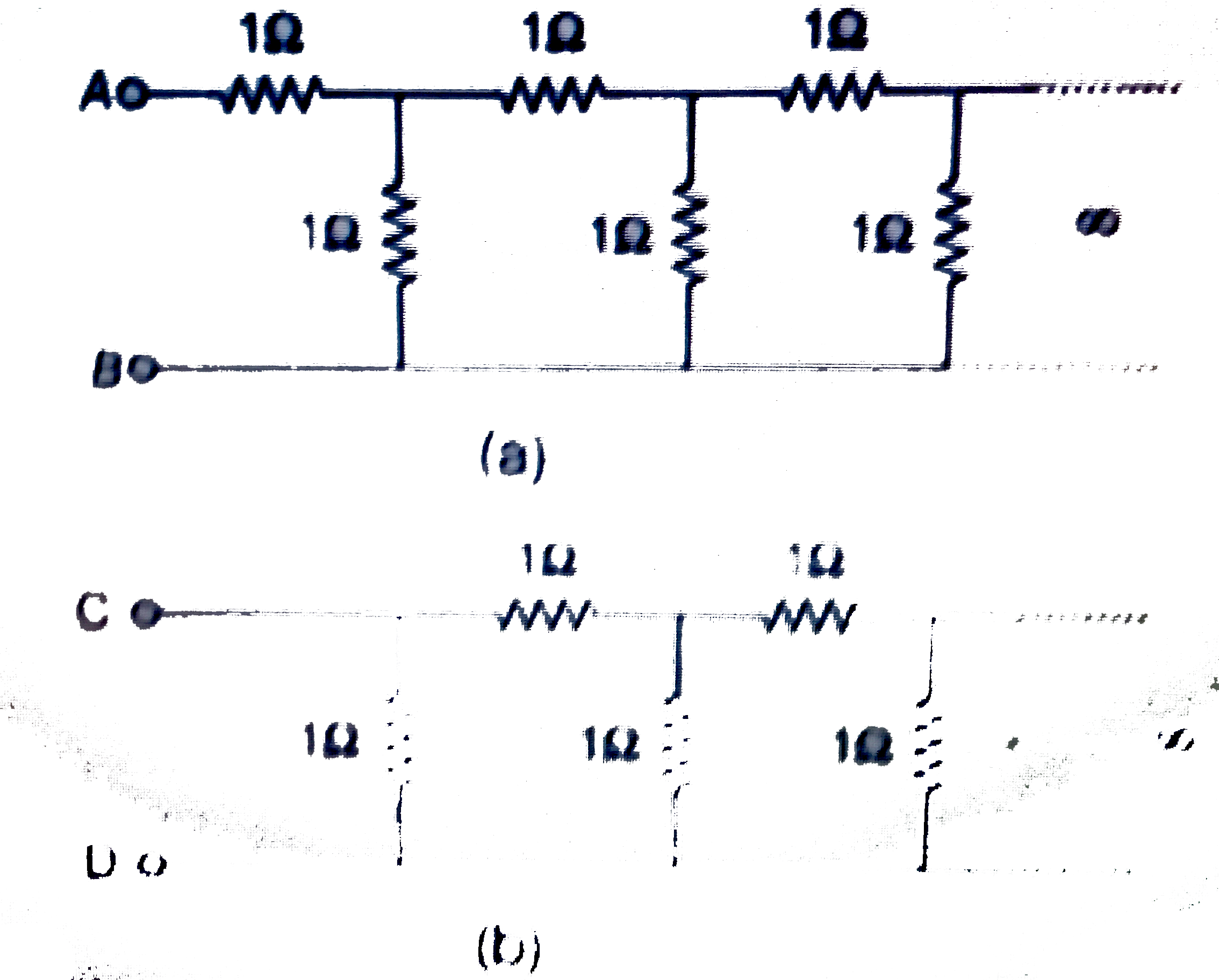 View Solution
In the circuit shown in figure
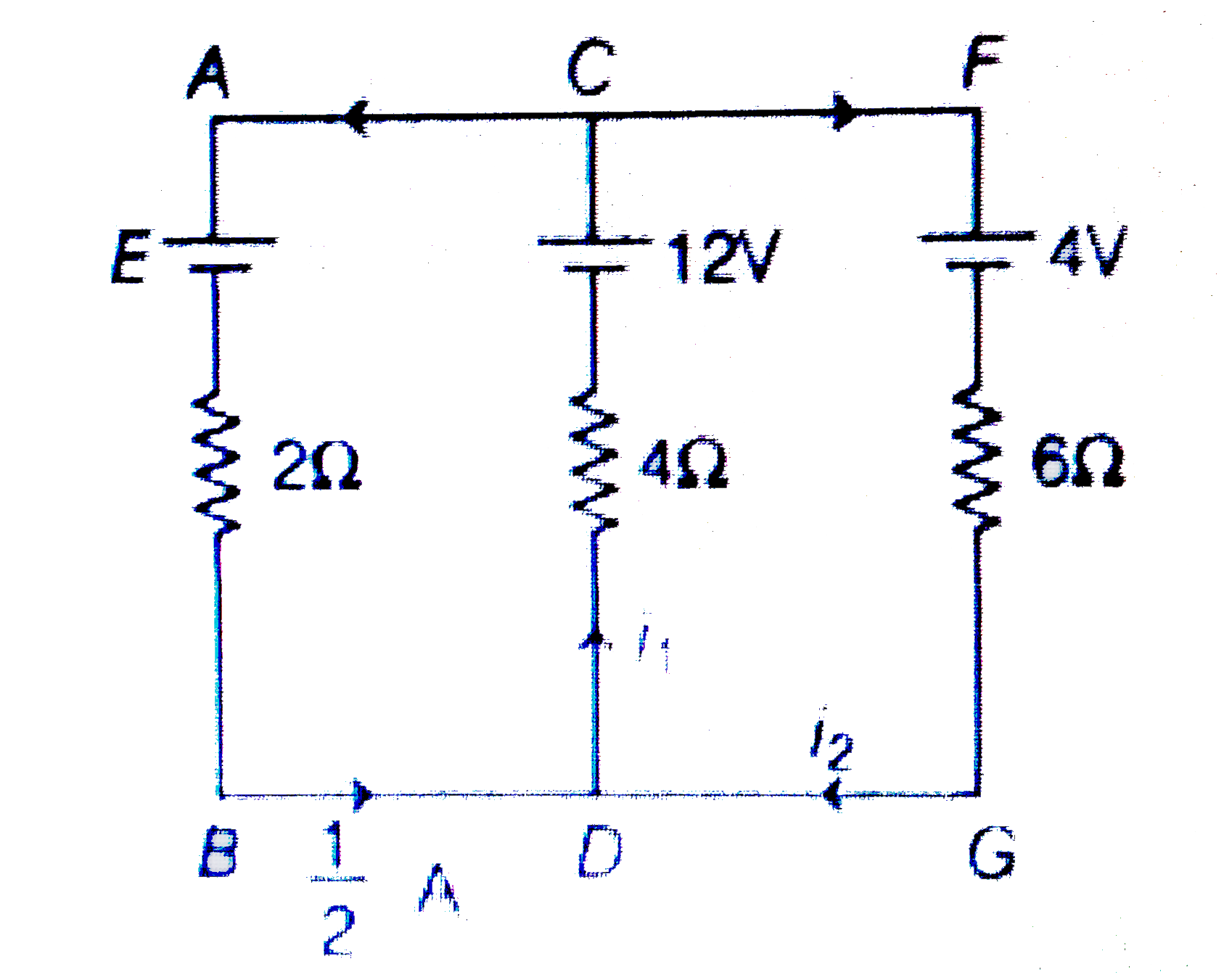 View Solution
In the circuit shown in figure
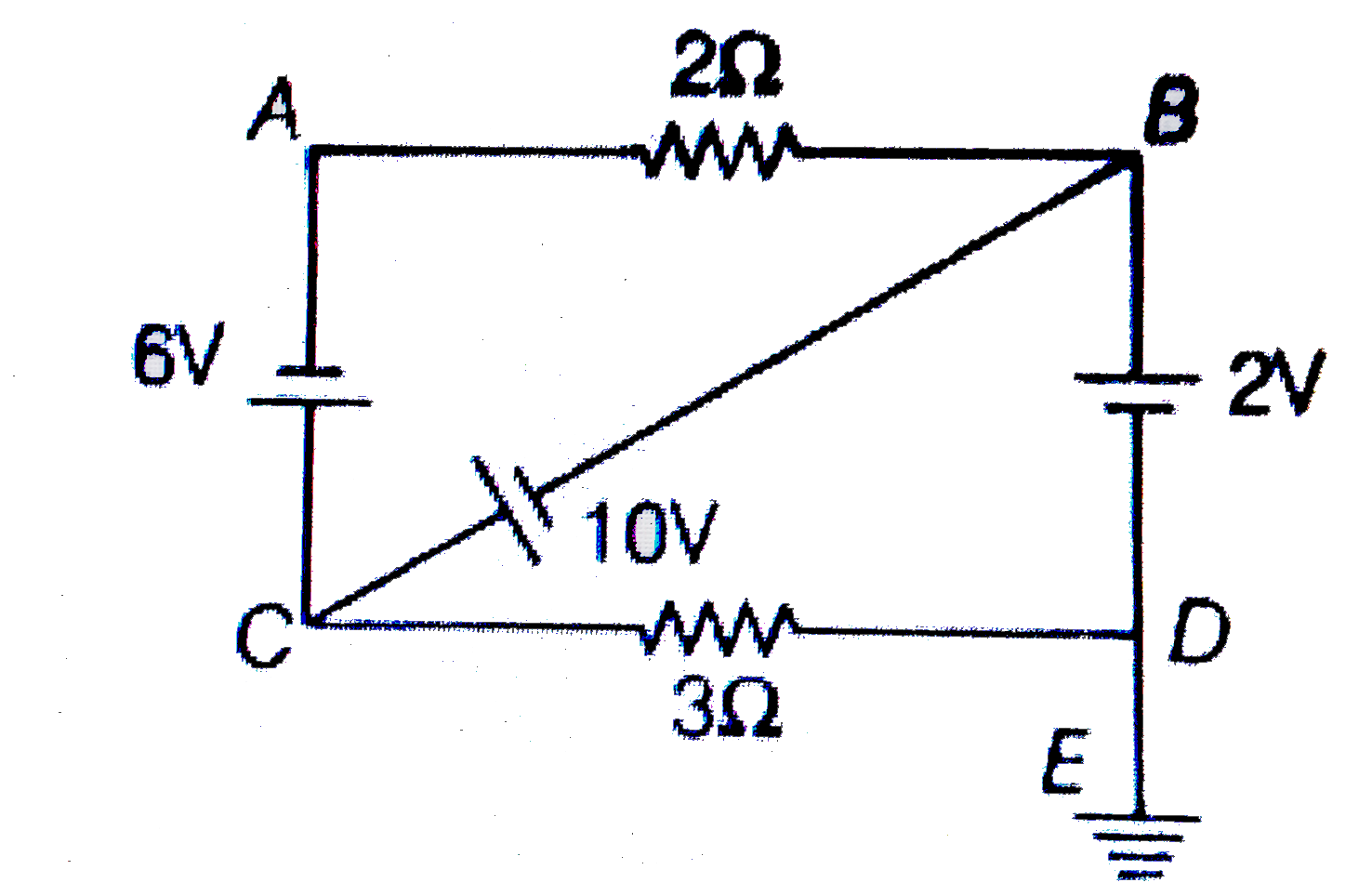 View Solution
In the circuit shown in figure
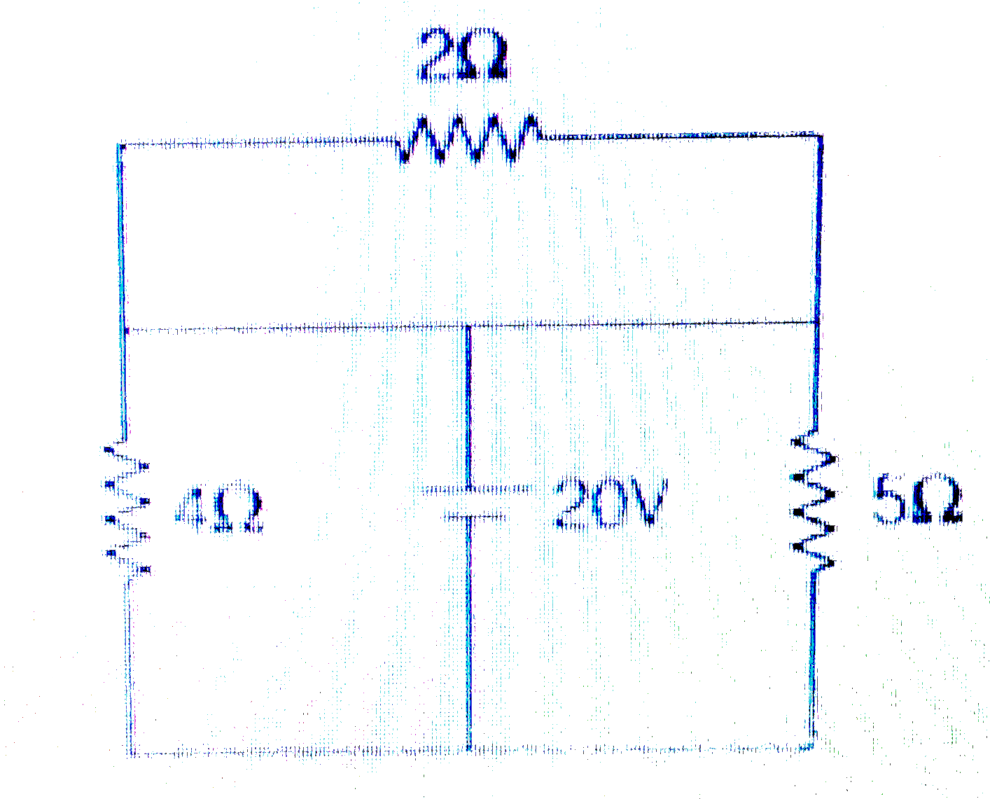 View Solution
In the circuit shown in figure
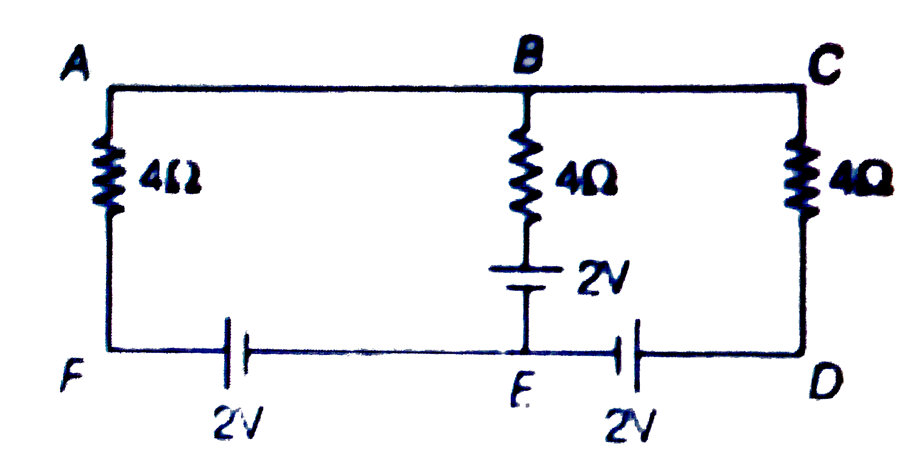 View Solution
In the circuit shown in figure
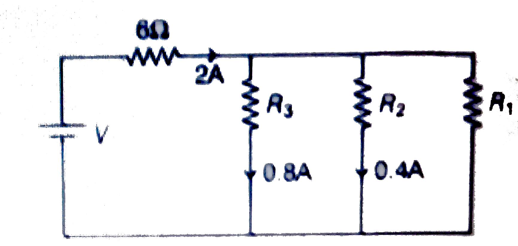 View Solution
In the circuit shown in figure
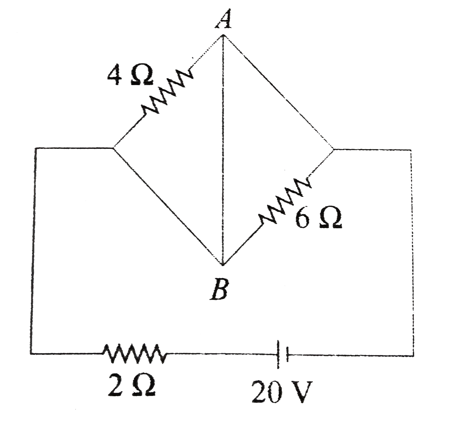 View Solution
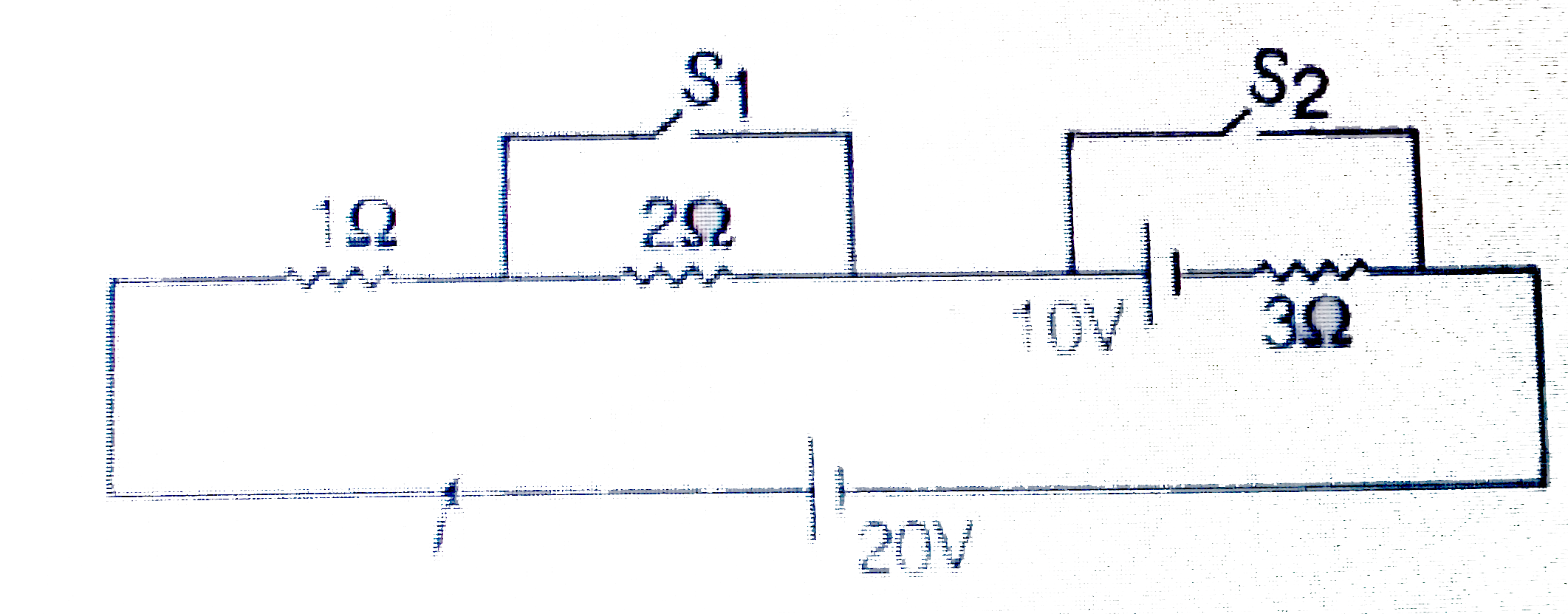
In the circuit shown in figure
 View Solution
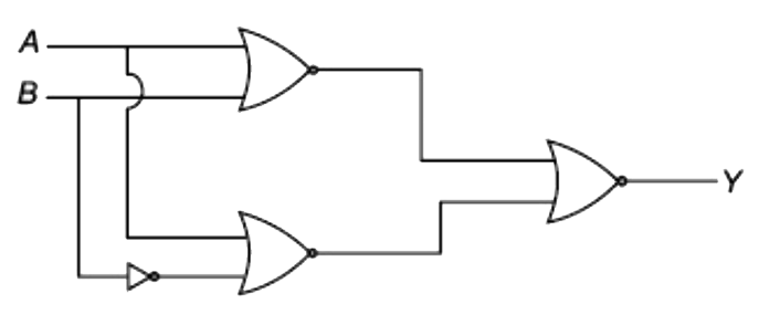
The output of the given logic circuit is
 View Solution

