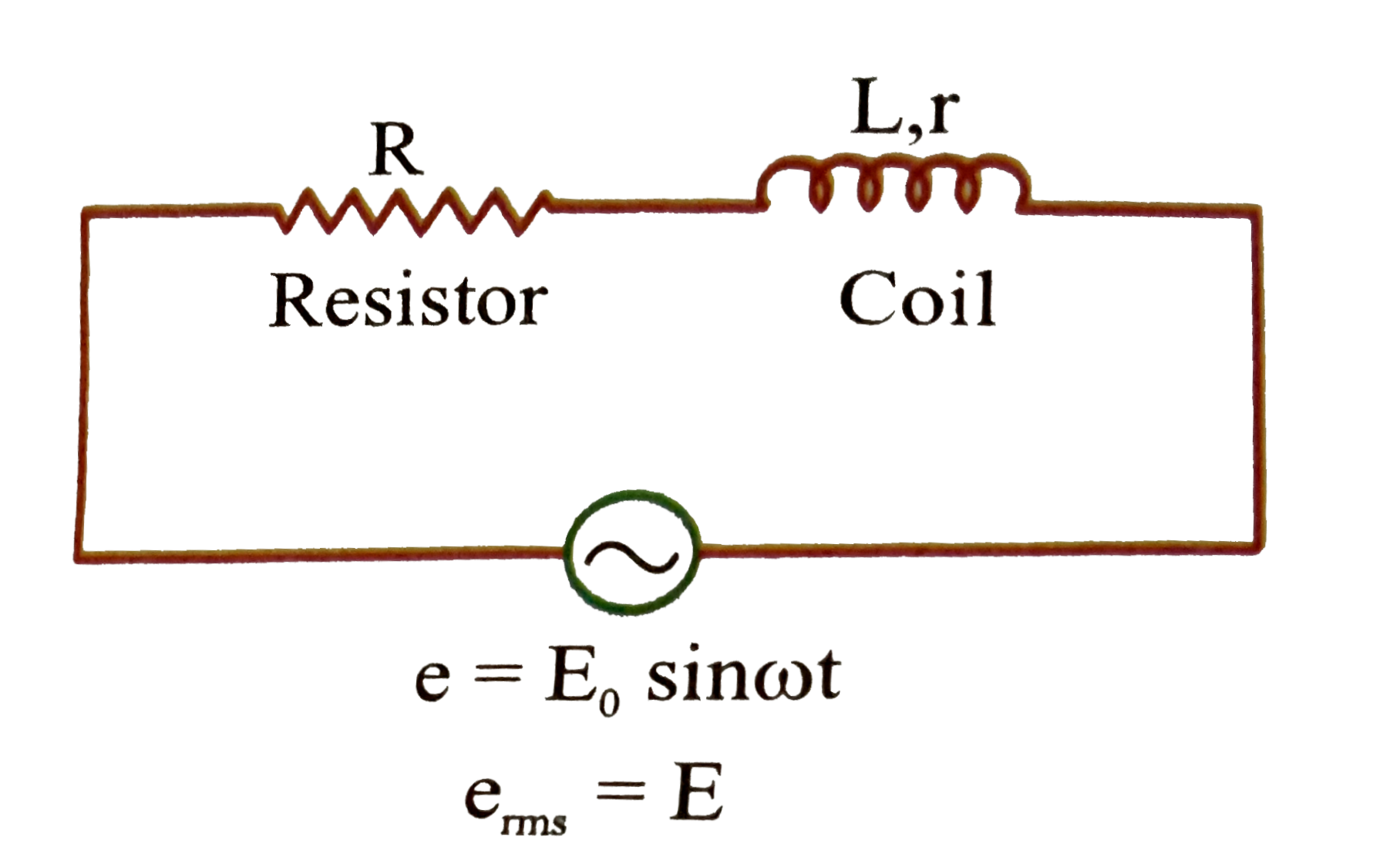
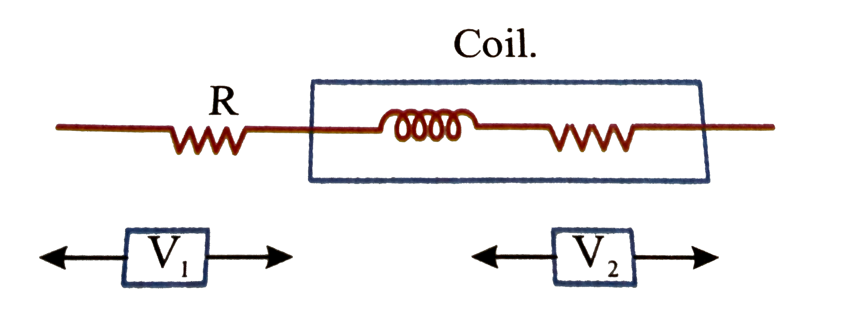
For the circuit shown in the figure the rms value of voltage across R and coil are E1 and E2 respectively.
The power (thermal) developed across the coil is
E−E212R
E−E21−E222R
E22R
(E−E1)22R
Step by step video & image solution for For the circuit shown in the figure the rms value of voltage across R and coil are E_(1) and E_(2) respectively. The power (thermal) developed across the coil is by Physics experts to help you in doubts & scoring excellent marks in Class 12 exams.
Updated on:21/07/2023Topper's Solved these Questions
Similar Questions
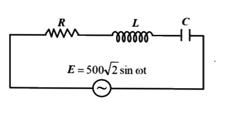
In the series L−C−R circuit shown in the figure, the rms voltage across the resistor and inductor are 400 V and 700 V respectively. If the applied voltage is E=500√2sin(ωt), then the peak voltage across the capacitor is
View SolutionIn an LCR series circuit the rms voltages across R L and C are found to be 10V,10V and 20Vrespectively.The rms voltage across the entire combination is
View Solution
Knowledge Check
In the circuit shown in figure, the final voltage drop across the capacitor C is :
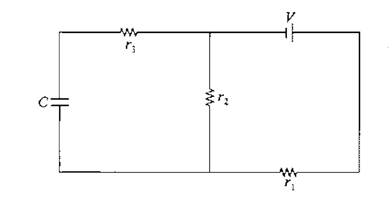 AVr1r1+r2BVr2r1+r2CV(r1+r2)r2DV(r2+r1)r1+r2+r3
In the circuit shown, tp across the 2R resistor muhe voltage drost be
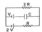 AVBV2C4V3D2V3
A resistor R is connected in series with a coil. The system is subjected to an AC supply of peak voltage V0. If the peak voltages dropped across the resistor R and the coil are V1 and V2 respectively
(a) The powerr dissipated in the coil is
V20−V21−V222R
The power dissipated in the circuit is
V20+V21−V222R
 AOnly (a) is correctBOnly (b) is correctC(a),(b) are wrongD(a),(b) are correct
In the circuit shown, the rms value of the voltage across the capacitor C, inductor L and resistor R1 are respectively 5√5V,10Vand5V.Thepeakvo<a≥(∈vo<)axrossR_(2) is
'(##CEN_KSR_PHY_JEE_C24_E01_018_Q08##)'
View SolutionIn the circuit shown in figure resistance of each wire is r. Net resistance across

View SolutionIn an LCR series circuit the rms voltages across R,L and C are foundd to be 10V,10V and 20V respectively. The rms voltage across the entire combination is
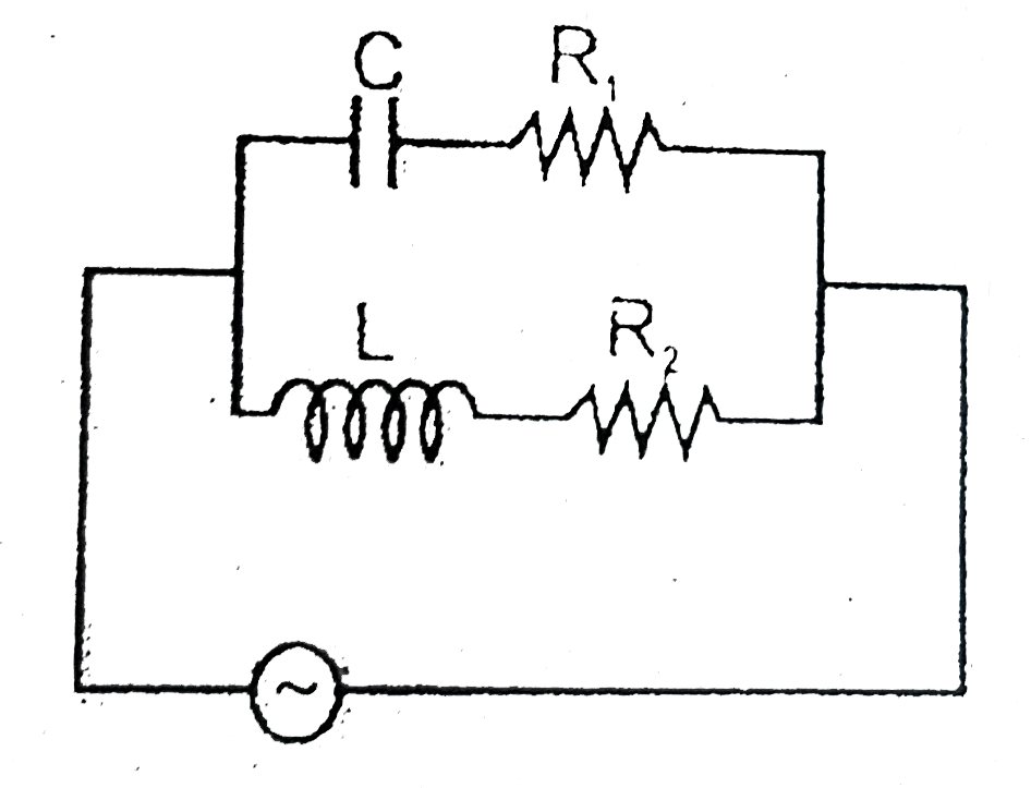
View SolutionIn the given circuit the R.M.S values of voltages across the capacitor C, inductor L and resistor R1 are 12V, 10V and 5 V respectively. Then the peak voltage across R2 is
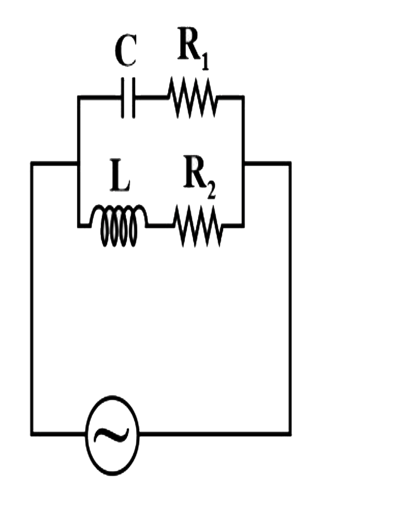
View SolutionIn the circuit the rms value of voltage across the capacitor C, inductor L and resister R1 are respectively 5√5V, 10 V and 5V. Then the peak voltage a cross R2 is
View Solution
