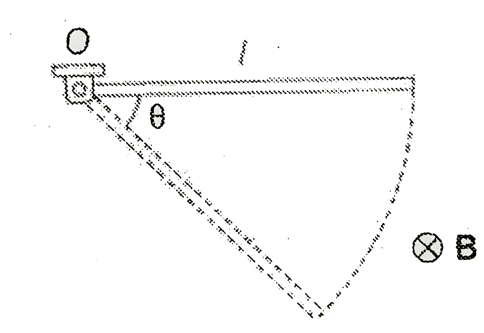
A thin, uniform rod with negligible mass and length 0.200m is attached to the floor by a frictionless hinge at point P (as shown in fig) A horizontal spring with force constant connects the other end of the rod to a vertical wall.The rod is in a uniform magnetic field B=0.340T directed into the plane of the figure. There is current I=6.50 A in the rod, in the direction shown.
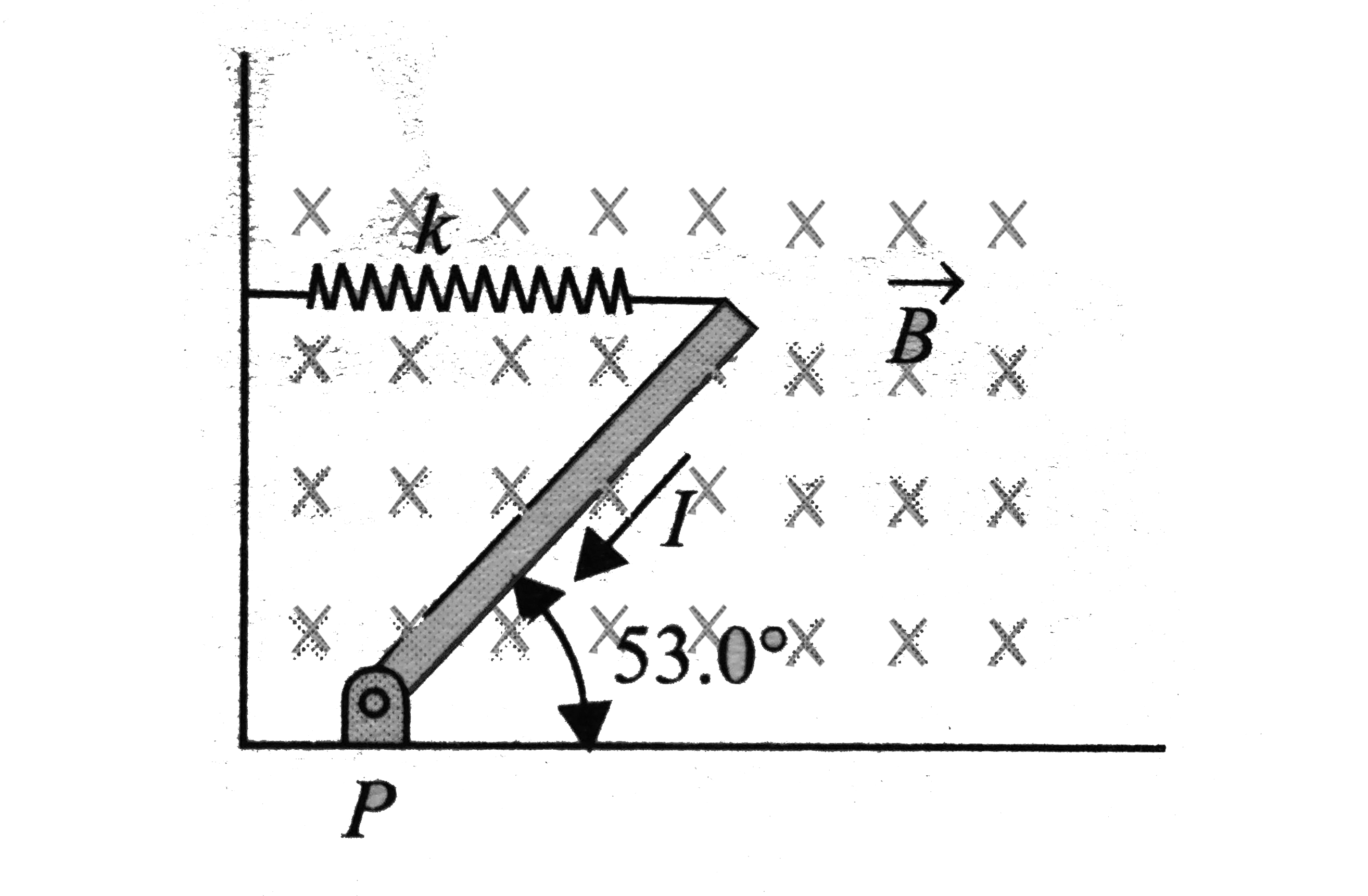
When the rod is in equilibrium and makes an angle of with the floor, is the spring stretched or compressed?
The correct Answer is:A, C
a. Yes, magnetic force for calculation of torque can beassumed at centre. Since variatonof torque about from one end of the rod to the other end comes out to be linear.
b. Magnetic torque on rod will come out to be clockwise. Therfore, torque of spring force should be anticlockwise or spring should be stretched.
b. In equilibrium,
clockwise torque of magnetic force
anticlockwise torque of spring force
Topper's Solved these Questions
- MAGNETICSBook:DC PANDEY ENGLISHChapter:MAGNETICSExercise:SCQ_TYPE
Explore 5 Videos
- MAGNETICSBook:DC PANDEY ENGLISHChapter:MAGNETICSExercise:MCQ_TYPE
Explore 1 Video
- MAGNETICSBook:DC PANDEY ENGLISHChapter:MAGNETICSExercise:SUBJECTIVE_TYPE
Explore 1 Video
- MAGNETIC FIELD AND FORCESBook:DC PANDEY ENGLISHChapter:MAGNETIC FIELD AND FORCESExercise:Medical entrance s gallery
Explore 59 Videos
- MAGNETISM AND MATTERBook:DC PANDEY ENGLISHChapter:MAGNETISM AND MATTERExercise:Medical gallery
Explore 1 Video
Similar Questions
A thin, uniform rod with negligible mass and length 0.200m is attached to the floor by a frictionless hinge at point P (as shown in fig) A horizontal spring with force constant k=4.80Nm−1 connects the other end of the rod to a vertical wall. The rod to a vertical wall. The rod is in a uniform magnetic field B=0.340T directed into the plane of the figure. There is current I=6.50 A in the rod, in the direction shown.

When the rod is in equilibrium and makes an angle of 53.0∘ with the floor, is the spring stretched or compressed?
View SolutionA thin, uniform rod with negligible mass and length 0.200m is attached to the floor by a frictionless hinge at point P (as shown in fig) A horizontal spring with force constant k=4.80Nm−1 connects the other end of the rod to a vertical wall. The rod to a vertical wall. The rod is in a uniform magnetic field B=0.340T directed into the plane of the figure. There is current I=6.50 A in the rod, in the direction shown.
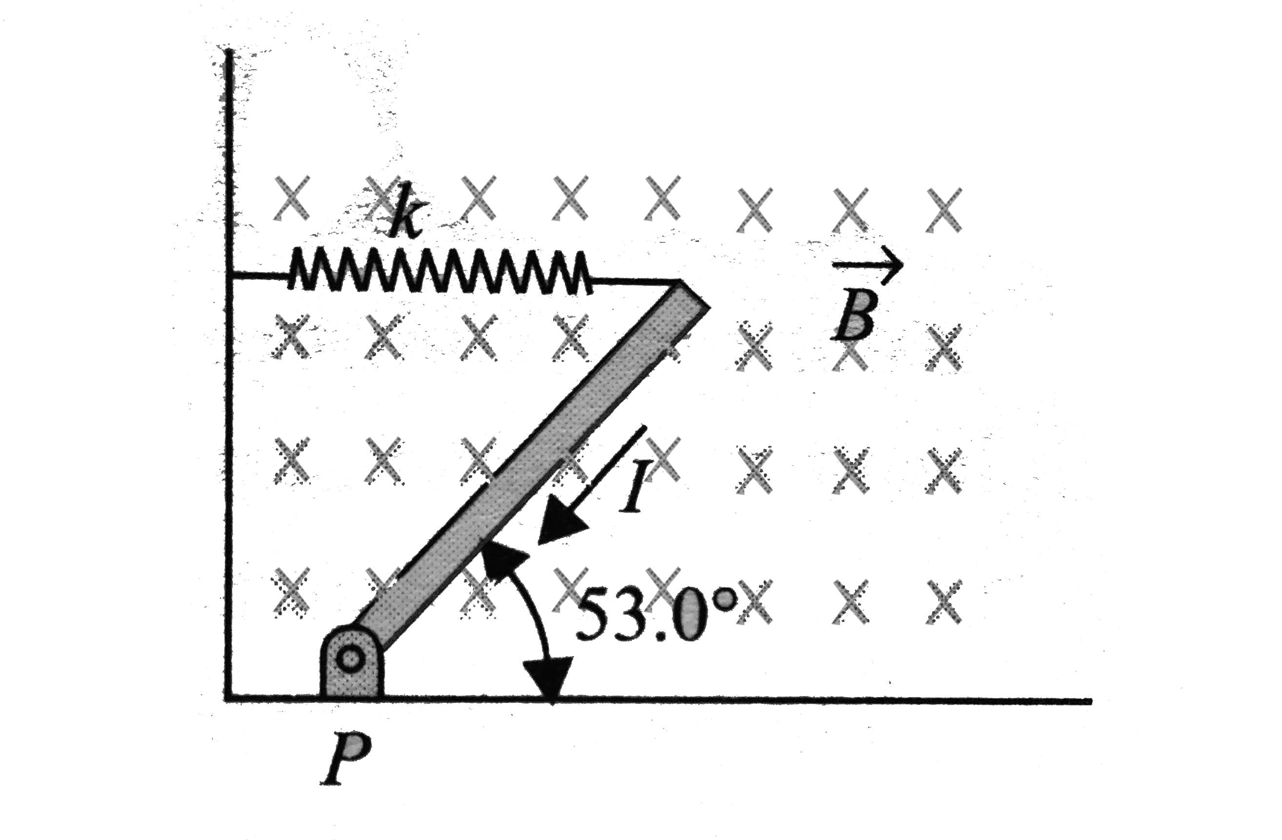
Calculate the torque due to the magnetic force on the rod, for an axis at P.
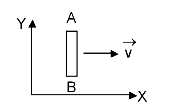
View SolutionA conductor rod AB moves parallel to X-axis in a uniform magnetic field, pointing in the positive Z-direction. The end A of the rod gets-
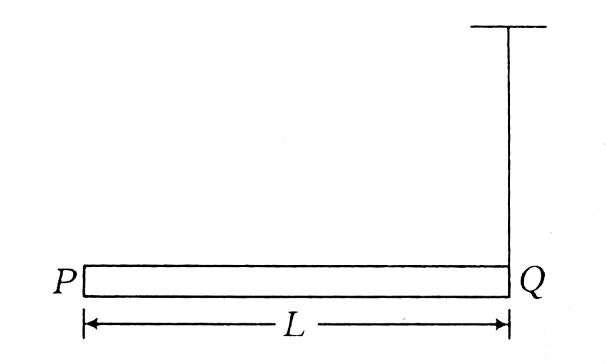
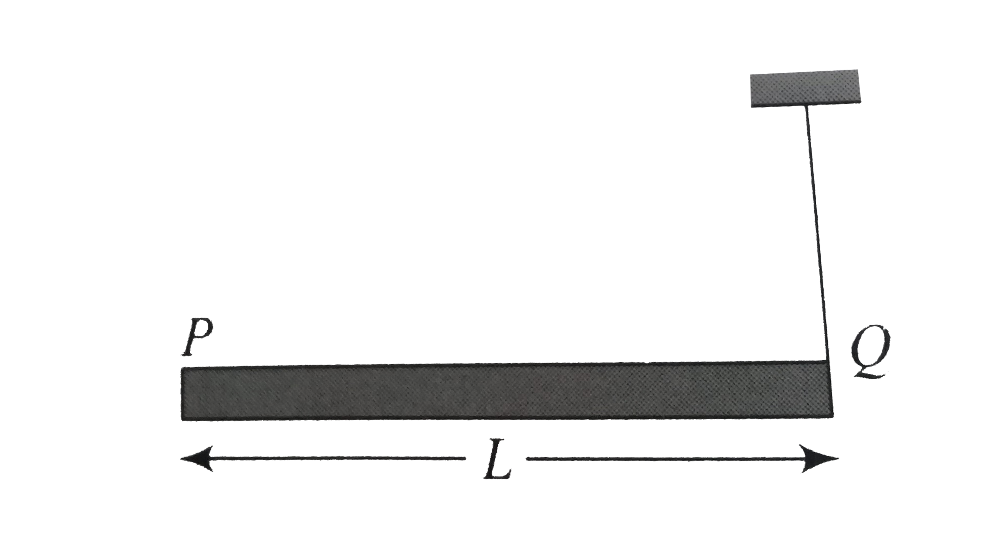
View SolutionA rod PQ of mass M and length L is hinged at end P. The rod is kept horizontal by a massless string tied to point Q as shown in figure. When string is cut, the intial angular acceleration of the rod is
View SolutionA rod PQ of mass M and length L is hinged at end P. The rod is kept horizontal by a massless string tied to point Q as shown in the figure. When string is cut, the initial angular accleration of the rod is.
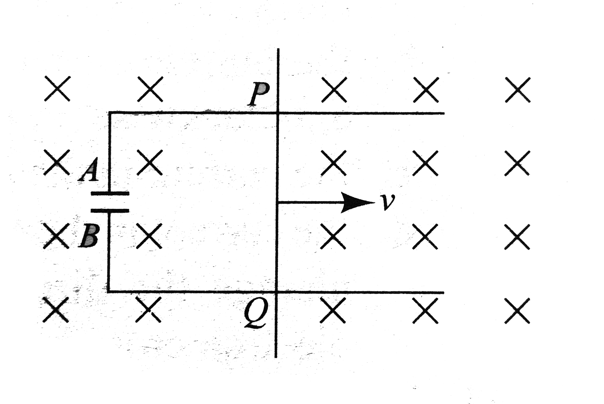
View SolutionA conducting rod PQ of length L=1.0m is moving with a uniform speed v=2.0ms−1 in a uniform magnetic field B=4.0T directed into the plane of the paper.
A capacitor of capacity C=10μF is connected as shown in , then
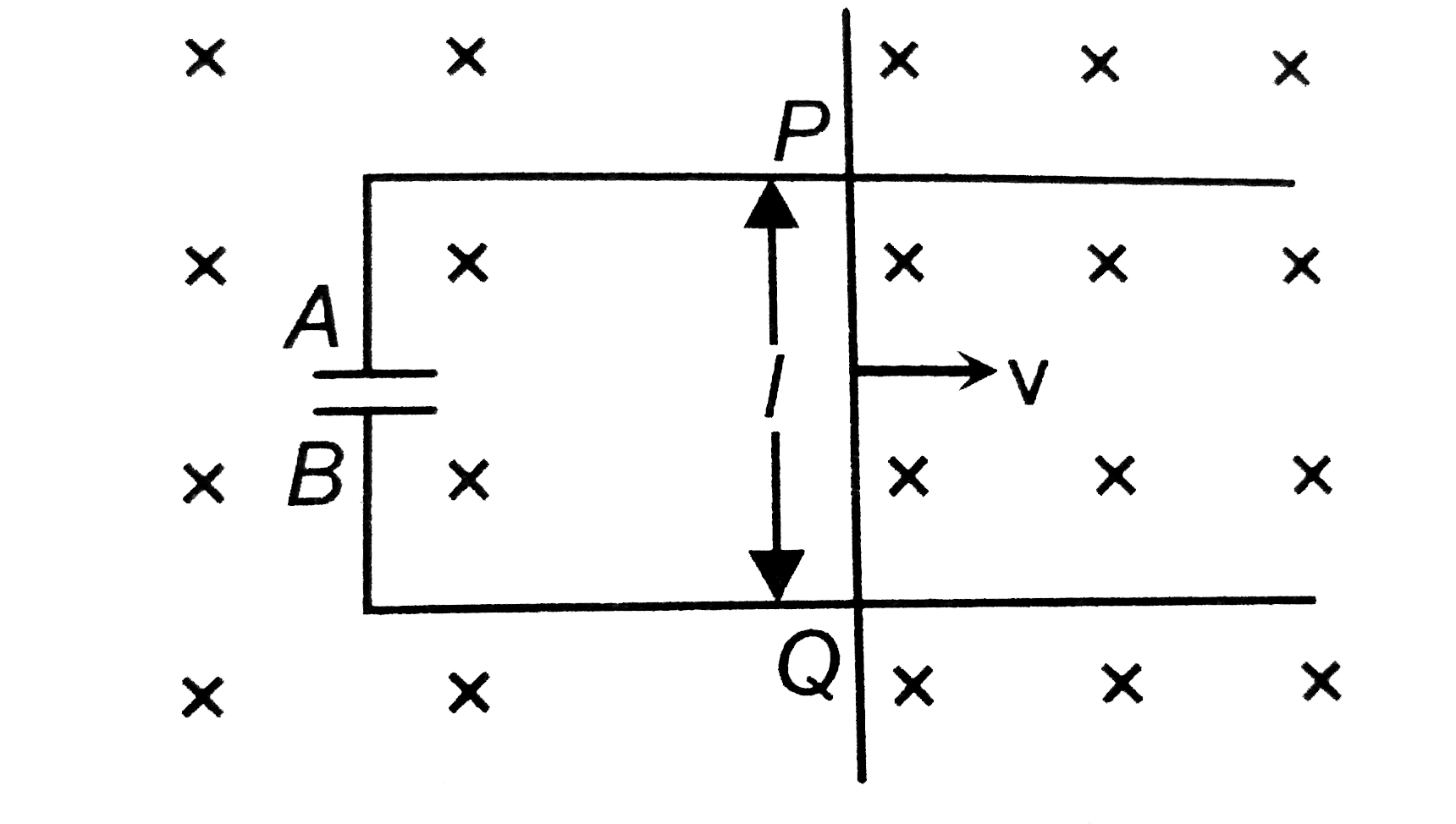
View SolutionA conducting rod PQ of length l=1.0m is moving with a uniform speed v2.0m/s in a uniform magnetic field B=4.0T directed into the paper.
A capacitor of capacity C=10μF is connected as shown in figure. Then
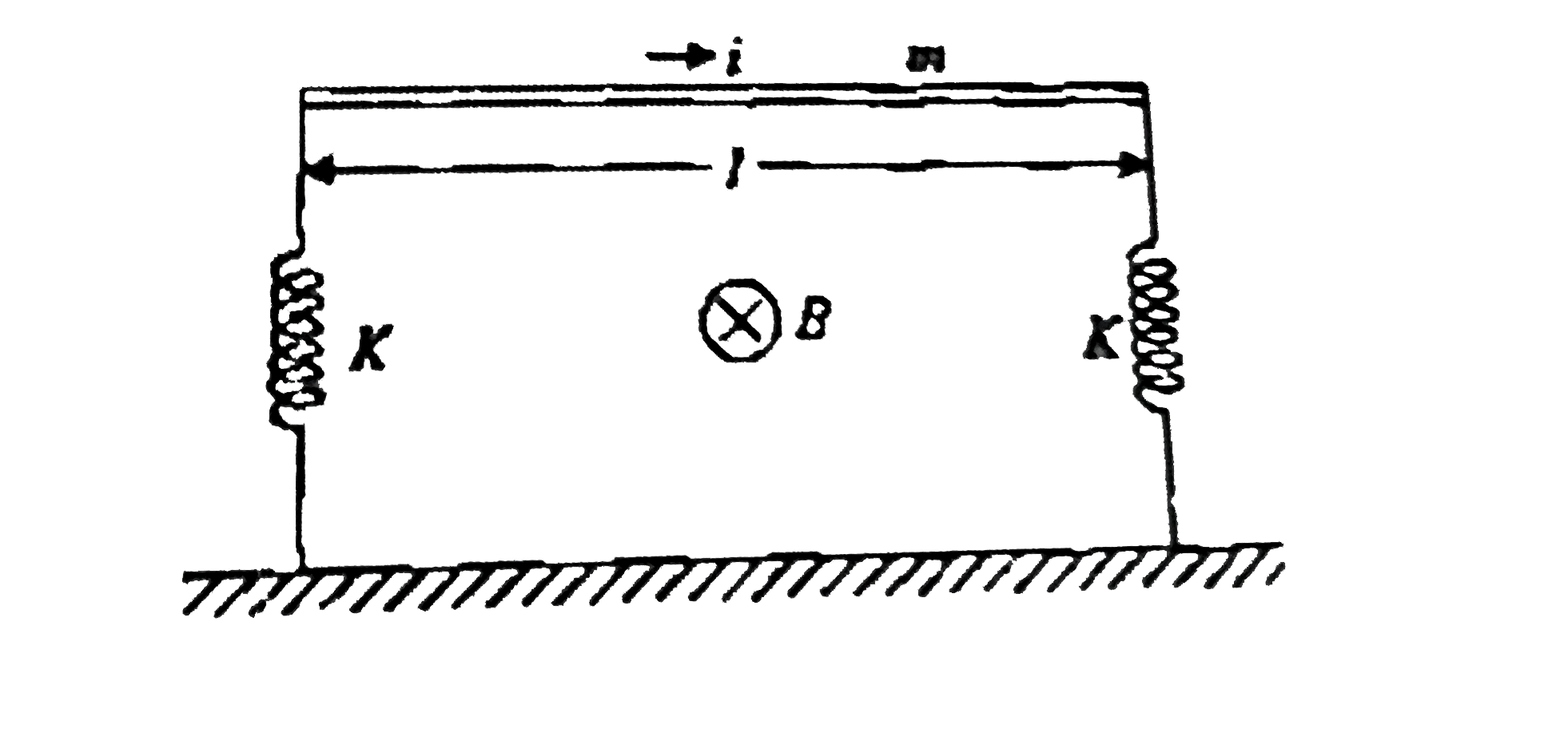
View SolutionA horizontal metallic rod of mass 'm' and length 'l' is supported by two vertical identical springs of spring constant 'k' each and natral length l0 A current 'l' is flowing in the rod in the direction shown if the rod is in equilibrium then the length of each spring in this state is:
View SolutionA uniform rod of mass m and length L is kept on a horizontal table with L4 length on the table as shown in figure. As the string attached to the end B is cut, the angular acceleration of the rod about point C will be
_PHY_E05_242_Q01.png)
View SolutionA conducting rod of length l is hinged at point O. It is a free to rotate in a verical plane. There exists a uniform magnetic field B in horizontal direction. The rod is released from the position shown. The potential difference between the two ends of the rod is proportional to
View Solution